Flocell XFM 900 Installation instructions

PLEASE READ INSTRUCTIONS THOROUGHLY BEFORE
INSTALLATION AND COMMISSIONING
FLOCELL XFM FILTERS
INSTALLATION & OPERATING MANUAL
TERMS & CONDITIONS

Contents
Introduction
Dimensions
Operational design
Specifications & Flow Rates
XFM Filter Installation
Media
Installation
Operation
Single Filters
Dual Filters
Series Filters
Cleaning Procedures
Single Filters
Dual Filters
Series Filters
Maximising efficiency / performance
Troubleshooting

Introduction
Flocell XFM filters are high performance, high capacity filtration units designed to capture large
quantities of suspended particles and are not subject to the typical restrictions of particulate filters.
Low cleaning frequency
Due to very high retention capacity, cleaning cycles are far less frequent than with other technologies
therefore increasing operational efficiencies.
No hydraulic pressure loss
XFM Filters do not suffer hydraulic loss and will continue to filter at low head until they reach retention
capacity and then require cleaning.
Low water use and air-cleaning
XFM filters are cleaned by air sparging for a short period of time before a single volume of
concentrated filtrate is sent to waste having first isolated the filter(s). They require either a pumped
or gravity supply.
Low operating costs
XFM filters have much lower operating costs associated with power and water use. Whilst not
typically used for absolute, single pass filtration, XFM filters instead work by constantly removing a
percentage of the particles present. In situations where single pass filtration is the only option,
multiple filters are installed in series/parallel or a screened balancing tank or sump is present in order
to continually filter a body of water.

Dimensions (in mm)

Flocell XFM filters are not designed to filter gross solids
and it is paramount that a pre-filter screen is present in
any situation where this may occur (see also
Maximizing Efficiency section).
Care should be taken to ensure the overflow is open
during cleaning to allow media to freely circulate and
to prevent pressure increase that will prohibit cleaning
of the installed filter pack
Operational design
Flocell XFM filters upflow units where inlet water is admitted to the filter body via
the lower tank connection. This connection is also used for filtrate removal after a
cleaning cycle.
Water flows up through the floating media pack and exits the filter through laterals
installed through the upper tank connection.
During a cleaning cycle, air is admitted to the filter body via an independent
connection having first isolated the inlet and outlet. After agitating the media for a
timed cycle, the now dirty filtrate is removed from the filter and sent to waste.

After cleaning, water is re-admitted to the filter to continue operation.
Specifications & Flow Rates
XFM 900
XFM 1200
METRIC
IMPERIAL
METRIC
IMPERIAL
Filter Diameter
915mm
36"
1200mm
48"
Filtration Area
0.64m2
6.9 SF
1.13m2
12.1 SF
Connection
63mm
2“
90mm
3"
Max Pressure
2.0bar
30 psi
2.0bar
30 psi
Optimal Flow Rate
16m3/hr
9.4 CFM
20m3/hr
11.8 CFM
Media Quantity
250 l
8.8 CF
1200 l
42.4 CF
Media
Flocell XFM filters use a proprietary open-cell media that has been optimised for
fine particle mechanical filtration.
The table below shows expected performance as a function of the particles
present, this can be used for mass balance calculations with the appropriate
gravimetric test results to optimise cleaning frequency.

Installation
NOTE: Filters are delivered conveniently packed and due to their weight, size and difficulties
arising in placing them, we recommend that their handling and movement be done with
mechanical apparatus (forklifts, cranes, etc.).
XFM filters should be installed as close as possible to the inlet supply and preferably
at a level of 0.50 metres below the surface of the water in a settlement vessel or
sump. Make sure there is accessible drainage for filter overflow.

It is imperative that inlet pressure does not exceed 2.0
bar or damage may occur to the filter
The filter must be installed on a flat, level base, on firm ground or equivalent. Ensure
the ground will not subside and strain pipework. We recommend using a flat solid
concrete surface as a base large enough for the filter to be installed.
Under normal operating conditions the filter will not clog or block but care must
be taken to ensure no gross solids are admitted to the unit. In situations where this
may occur it is vital to install the system so that water flow can be reversed in order
to clear any potential blockage and allow for normal operations to continue.
In situations where no gravity supply (or waste) is possible, pumps must be
installed for both inlet supply and waste filtrate removal.
Pump selection should be considered carefully as high-speed impeller pumps will
degrade larger particles thus decreasing operational efficiency. As XFM filters do
not suffer any hydraulic pressure increase, a high-volume pump should be used in
conjunction with a current inverter so flow rates can be adjusted accordingly and
power use optimised.

The installed air blower must be sited above the filter body or a
non-return valve installed before the air-supply to limit the
potential for accidental water ingress to the blower
Operation
•Before working on the filter or valves, make sure the pump is switched off
and the filter is de-pressurised. For greater safety, disconnect the pump and
possible electric installations connected to the mains.
•Never connect the filter directly to the water supply, since it’s pressure can
be higher than the maximum pressure of the filter (2bar / 30psi).
•As the parts connect using O-rings, it is not necessary to overtighten any
nuts / bolts.
•Do not clean plastic parts with solvents.
•Do not let children handle the filter or play near them.
•Protect the filter from freezing.
•Before connecting the pump, make sure that the filter lid is closed.
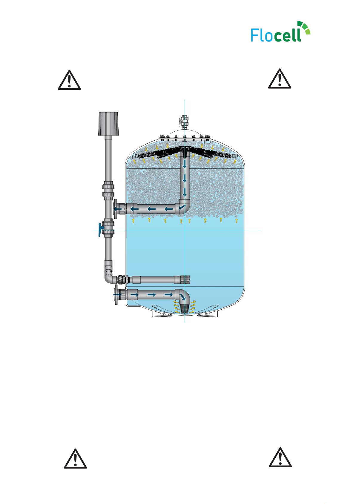
•Install the filter in an area with ventilation and adequate drainage as close
as possible to the water body, below the water level to help prevent an air
lock or vacuum from occurring.
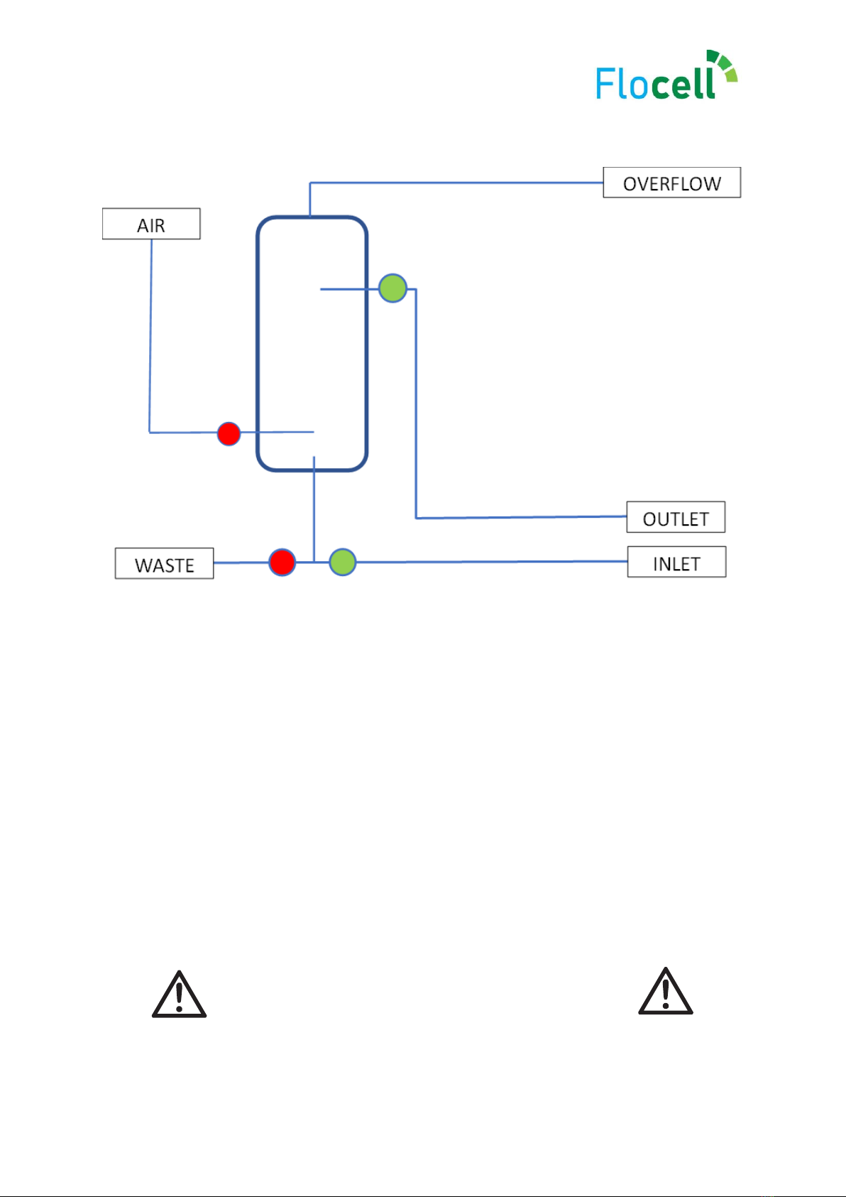
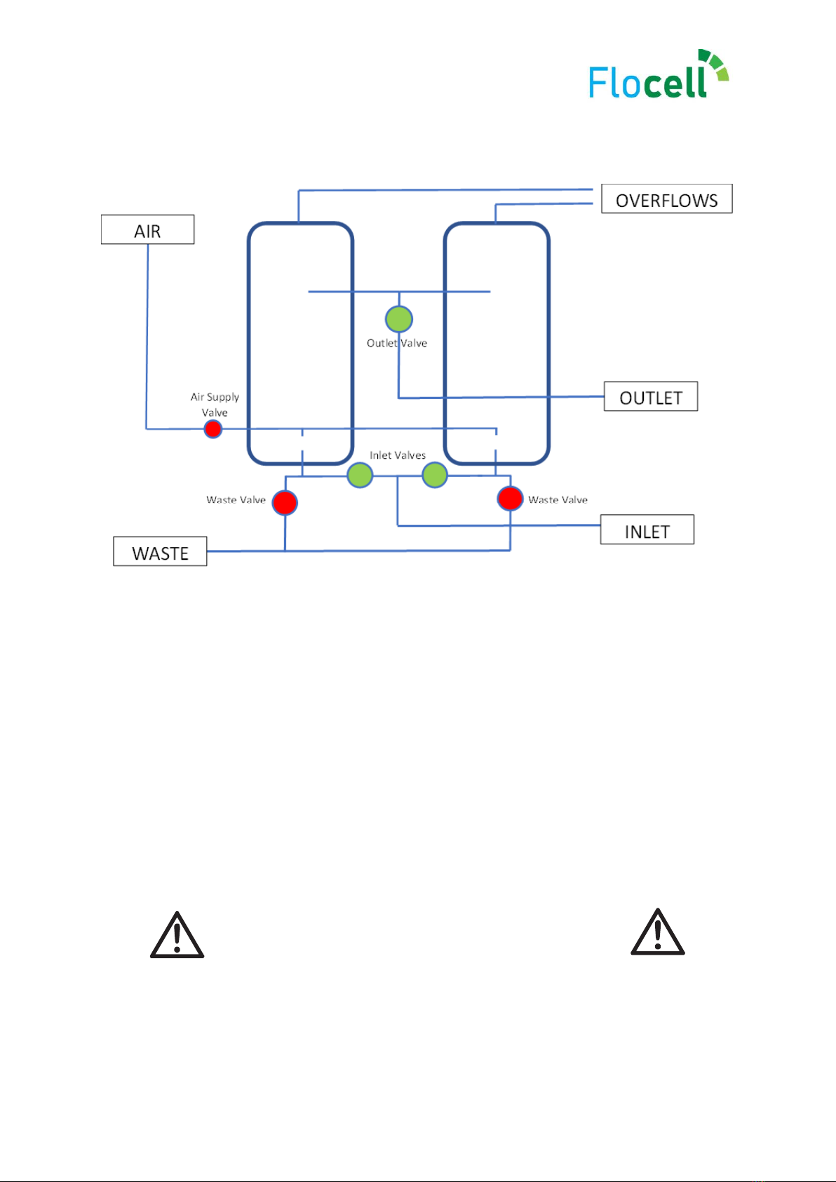
IMPORTANT –USE OF VALVES ON OVERFLOW LINE
In certain situations it may be beneficial to install a valve on the overflow line.
These situations may include (but are not limited to):
•Larger installations where multiple filters are installed in series or parallel
which may require independent cleaning but that have a linked overflow
line.
•Situations where an open return is a significant distance from drain, where
water recovery is vital but that cannot accommodate a suitable pipe-run.
Care MUST be taken to ensure that when cleaning, the overflow line is OPEN. This
will allow for the media to be circulated by incoming air. If the overflow line is not
open, the incoming air will cease and the filter pack will not be able to be cleaned.

Always ensure air supply valves are CLOSED before
operating filter to ensure no water ingress to blower.
Single Filters
In single filter situations, the inlet supply is connected to the lower tank connector
with an isolation valve.
The outlet is connected to the upper connector with an isolation valve.
In situations where continuous supply is encountered, a bypass should be installed
back to the ‘dirty’ watercourse before the main inlet supply valve.
Overflow line should be installed either open to a drain or back to the nearest pre-
filtration water supply by an open return.
To operate filter open Inlet Valve and open Outlet Valve ensuring Waste Valve is
closed.
Note GREEN open valves and RED closed valve positions
OutletValve
Inlet Valve
Waste Valve
Valve
Air supply
Valve

Always ensure air supply valves are CLOSED before
operating filter to ensure no water ingress to blower.
Parallel Filters
In dual or any multiple parallel filter situations, the inlet supplies are connected to
the lower tank connectors via a manifold with isolation valves to allow flow
balancing. Either a manifolded single or individual connections to the main inlet
line are possible but in the case of an single connection, individual balancing valves
are required for optimal performance.
The outlets are attached to the upper connectors by way of a manifold with a main
valve on the manifold leg to allow for isolation.
In situations where continuous supply is encountered, a bypass should be installed
back to the ‘dirty’ watercourse before the main inlet supply valve.
To operate filters, open Inlet Valves and Outlet Valve.
Note GREEN open valves and RED closed valve positions

Always ensure air supply valves are CLOSED before
operating filter to ensure no water ingress to blower.
Series Filters
In series filter situations, the main inlet supply is connected to one side of the T
fitting on the lower tank connectors of the filters with an isolation valve to allow for
cleaning.
The outlet of the first (and subsequent) filter(s) is connected to the inlet side of the
T fitting on the lower tank connector(s).
The waste line is connected with valves to both filters via the unused side of the
lower T connectors, this can be achieved by way of a manifolded line.
To operate, open Inlet Valves, close Upstream and Downstream Mainline valves
(two shown on schematic), open both Outlet Valves.
Inlet flow passes through filter 2 then filter 1 to allow for continuous filtration.
Note GREEN open valves and RED closed valve positions.

It is imperative that inlet valve is always closed before
outlet valve to prevent excess pressure.
Cleaning Procedures
Single / Parallel Filters
To clean filter, firstly isolate filter by closing Inlet and Outlet Valves. Open Waste
Valve and send water to waste for approximately 1 minute to allow an air space to
form at the top of the filter.

After 1 minute, close Waste Valve and open Air Supply Valve and turn on Air
Blower.
Allow 10 minutes for the media to circulate before turning off Air Blower and then
closing Air Supply Valve.
Finally, send filter contents to waste by opening Waste Valve until filter body is
empty.
To refill filter turn off Air Supply Valve and close Waste Valve. Open Inlet and
Outlet valves.
For optimal efficiency, undertake a second cleaning cycle once filter refilled.

Parallel Filters
To clean filters installed in parallel, firstly isolate filters by closing Inlet and Outlet
Valves.
Open Waste Valves and send water to waste for approximately 1 minute to allow
an air space to form at the top of the filter.

After 1 minute, close Waste Valves and open Air Supply Valve and turn on Air
Blower. Allow 10 minutes for the media to circulate.
Finally, send filter contents to waste by opening Waste Valves until filter body is
empty.

To refill filter turn off Air Supply Valve and close Waste Valves. Open Inlet and
Outlet valves.
For optimal efficiency, undertake a second cleaning cycle once filter refilled.

Series Filters
In series operation, filters can be cleaned and isolated individually as required.
In normal operations, the downstream filter will require cleaning approximately
50% less frequently than the upstream filter.
To clean filter 2 (as primary filter) isolate by opening Upstream Mainline Valve to
divert flow then close Inlet then Outlet Valves of Filter 2.
Open Filter 2 Waste Valve for 1 minute to allow air space creation for media
circulation.

Close Filter 2 Waste Valve and open Filter 2 Air Supply Valve, turn on Filter 2 Air
Blower and allow media to circulate for 10 minutes.
Open Filter 2 Waste Valve and allow filter to empty to waste.
When Filter 2 is empty, close Filter 2 Waste Valve. Close Filter 2 Air Supply Valve
and turn off Filter 2 Air Blower.

To refill Filter 2 and bring back on line, close Filter 2 Waste Valve, open Filter 2
Inlet and Outlet Valves close Upstream Mainline Valve.
Filter 1
To clean filter 1 isolate by opening Downstream Mainline Valve then closing Filter
1 Inlet then Outlet Valves.
This manual suits for next models
1
Table of contents
Popular Water Filtration System manuals by other brands

Living Waters
Living Waters AuaRinse LWMMF10 How-to

Virgin
Virgin T6 WaterBar care guide

flamco
flamco MeiFlow Shunt UD DN15 S Installation & service instructions

Beko
Beko QWIK-PURE 25 Instructions for installation and operation

Trox Technik
Trox Technik PFC Installation and maintenance manual

Tetra
Tetra Tetratec EasyCrystal FilterBox 300 manual

A.O. Smith
A.O. Smith Pure&Sure 329843-000_R0 user guide

DuPure
DuPure EcoPur S-Series user manual

Kemper
Kemper Clean Air Tower operating instructions

DiaSys
DiaSys O MINI Operator's manual

Cornelius
Cornelius QLT 180 INSTALLATION & CLEANING INSTRUCTIONS

Aquadistri
Aquadistri SuperFish Aqua Pro Feeder quick start guide