Flotronic One-Nut User manual

The simplest ideas are often the best
Flotronic ‘One - Nut’ pumps
Installation Operation and
Maintenance Manual
Diaphragm Leak
Detection System
PLEASE KEEP FOR
FUTURE REFERENCE
ATEX APPROVED PUMPS
ATEX Gas
Group IIC
compliant
pumps now
available
W: www.flotronicpumps.co.uk
E: sales@flotronicpumps.co.uk
S: www.flotronicspares.co.uk

Contents
Warnings 3
Overview 4
Installation 6
Operation 9
Maintenance 10
Troubleshooting 13
Technical Specifications 14

Warnings
The following warnings are for the setup, usage, grounding, maintenance and
repair of the Leak Detection System.
WARNING
Electric Shock Hazard
Improper grounding, setup or usage of this equipment can cause electric
shock.
Remove power before connecting or disconnecting cables and
accessories to the unit.
Electrical installation must be carried out by a qualified electrician and
comply with all local codes and regulations.
Unit must be grounded to ensure user safety.
Equipment Misuse
Misuse can cause serious injury or death.
Do not exceed the maximum pressure or temperature rating of the
lowest rated system component. Read all technical documentation
related to the equipment and ensure compliance.
Only pump products that are compatible with the pump wetted parts.
Do not modify the equipment.
Check the device and installation daily and replace any worn or
damaged parts immediately using genuine Flotronic Pumps spares.
Cables should be routed to avoid damage.
Personal Protective Equipment
Appropriate personal protective equipment must be worn when operating,
servicing or working in the equipment area.
CAUTION
To prevent the risk of electric shock, do not remove cover. No user-
serviceable parts inside. Refer servicing to qualified service personnel.
NOTE:
This unit MUST be earthed/grounded.

Overview
System Description
The leak detection system monitors Flotronic Double Diaphragm pumps for
diaphragm failure that could cause contamination of the product being pumped
and/or the air control systems internal to the pump and/or the immediate area
surrounding the pump.
The system comprises of two sensors and a main control unit. The two sensors are
connected to the air side of the pump and constantly monitor the air chambers for
the presence of foreign material that would indicate a diaphragm failure. Upon
sensing a diaphragm failure the main unit stops the pump by activating a solenoid
valve, (customer supplied), in the pump air supply line. The fault is also indicated
on the main control unit by the flashing of a red LED.
Main Components
It is recommended that you should familiarise yourself with the system before
installation and operation. This will help ensure optimum system performance.
Sensors
The sensors are mounted on the pump, one per air chamber, to detect the
presence of foreign material other than air on the driving side of the diaphragms.
The sensors are of a capacitive type and detect changes in a self generated
capacitive field. This means that they do not rely on a conductive or transparent
pumped media and can function correctly with most substances that may be
pumped.
Another benefit of this sensor type is the ability to sense through a barrier, in this
case a protective PTFE housing that stops the sensor from directly contacting the
pumped media. To this end the system can be used to detect most aggressive
substances that are compatible with PTFE

Main Control Unit
The main control unit powers the sensors and continuously monitors their output
state, ensuring a fast response to any possible diaphragm failure. If the main
control unit detects a failure from either sensor the red LED on the front panel will
flash. Simultaneously the solenoid output is de-activated and the connected
solenoid valve, (customer supplied), stops the air flow to the pump thus stopping
the pump.
The main unit latches in the alarm condition until the failure has cleared and the
unit is reset by pressing the front panel mounted Reset button. If the failure mode is
still present, i.e. pumped media still contaminating the sensors, the unit will not be
able to be reset until the failure has been rectified.
If there is a power failure to the main unit, the default pump operation mode is off
and the pump will be stopped. Upon power supply being restored the unit will stay
in the pump off condition until the Reset button is pressed.
The main control unit will alarm and set to fail condition if the sensors are not
connected or if the sensors fail to operate within their normal parameters.
There is a volt free relay connection that can be wired for either normally open or
normally closed configurations upon an alarm state. This connection can be used
to either monitor the unit’s state, i.e. running or fault, or to control another piece of
equipment that depends on a particular pump state. NOTE – This connection is a
volt free relay connection with a maximum rating of 1A @ 30V.
NOTE:
To fully comply with the 3A standard there must be a solenoid valve connected to
the main control unit to enable the pump to be stopped once a failure mode is
detected.
The solenoid valve needs to be fitted to the air pipe supplying the pump. See
Technical Data section for solenoid specifications.

Installation
System Connection
The main unit is fitted sockets for the connection of the two sensors and solenoid
valve and a 150mm hard wired lead fitted with a socket and plug for mains power
connection.
The sensors are supplied pre-wired for immediate use.
The solenoid valve, volt free relay and mains power connection plugs are user
connectable using screw terminals internal to the plugs. (Plugs supplied with main
unit)

Power Connection
Be sure that the power supply voltage of the area where this unit will be used
meets the voltage requirements, 96 – 264Vac @ 50/60Hz, of the main control unit.
Please observe the wiring code below, if in any doubt please consult a qualified
electrician.
NOTE:
This unit MUST be earthed/grounded by connecting a suitable earth connection to
the plug terminal marked as Earth on the connection diagram below.
Main Power Connection
NOTE:
Cable should be prepared as shown in diagram above

Main Power Connection (continued)
L = Live (96-264 Vac)
N = Neutral (96-264 Vac)
E = Earth
Internal screw terminals
are lettered.
Solenoid Valve Connection
1 = N/C
2 = +24 Vdc (positive)
3 = N/C
4 = -24 Vdc (negative)
Internal screw terminals
are numbered.
Volt Free Relay Connection – MAX 1A @ 30V
1 = Normally Open Connection
2 = N/C
3 = Normally Closed Connection
4 = Common
Internal screw terminals
are numbered.
N/C = NO CONNECTION

Leak Detector Operation
During normal operation only the ‘Power’ LED on the main control box will be lit
continuously.
If a fault develops, i.e. from diaphragm or sensor failure, the ‘Fault’ LED will light
flash and the pump will stop.
To reset the system after a failure has occurred, and the cause has been rectified,
press the ‘Reset’ button.
If there is an interruption to the power supply to the main control unit the pump will
stop, to restart the pump press the ‘Reset’ button.

Maintenance
NOTE:
Always disconnect the power supply from the control box before any maintenance
or cleaning operation is carried out.
Clean Sensors
In the event of a diaphragm failure the sensor housing will need to be cleaned to
remove all traces of product that may stop the system from resetting and thus the
pump from re-starting.
1. Unplug the sensors from the main control box.
2. Remove air domes from pump. (See pump IOM for details)
3. Clean the sensor port on the inside of the air dome to remove all traces of
product.
4. Dry the sensor port. Any cleaning solution left in the chamber may be
detected as a failure upon system re-start.
5. Rebuild pump replacing failed components.
If the contamination is difficult to remove from the port it is possible to unscrew the
PTFE sensor housing from the air dome to gain better access. If this is required
ensure that upon re-assembly the metal sealing ring is positioned over the external
thread of the PTFE housing to provide a seal between the air dome and the PTFE
sensor housing.
NOTE:
Ensure that the cleaning solution used is compatible with the items being cleaned.
Care should be taken not to apply harsh cleaning chemicals to the exposed sensor
section on the outside of the pump.

Main Control Unit
The main control unit requires no maintenance, should a fault be suspected please
notify Flotronic Pumps Ltd who can advise the best course of action. It may be
necessary to return the item to Flotronic Pumps Ltd for investigation.
Test System Function
The system should be checked for proper function every 3 months or earlier if a
problem is suspected.
Sensor Check
1. Disconnect the power supply to the main control unit.
2. Switch off the air supply to the pump.
3. Unplug the sensors from the main control unit.
4. Unscrew the PTFE sensor housings from the air domes complete with
sensors.
5. Reconnect the sensors to the main control unit.
6. Reconnect the power supply to the main control unit.
7. Ensure the flat front face of the PTFE sensor housings are clear of any
obstructions that could be sensed.
8. Reset the main control unit by pressing the Reset button.
9. The fail LED on the main unit should turn off with the power light remaining
on.
10. Place your hand close to the flat front face of one of the PTFE sensor
housings. The main control unit should register a fault and the LED fault light
should illuminate.
11. Repeat steps 7 to 9 for the other sensor.
NOTE:
If the main control unit fails to register a fault condition during the above tests, or it
constantly registers a fault condition please refer to the ‘Troubleshooting’ section at
the back of this manual or contact Flotronic Pumps Ltd for advice.

Pump Shut Down Check
Once it is confirmed that the sensors are functioning correctly the pump should be
reassembled to perform the ‘pump shut down check’.
To perform this check:
1. Connect the power supply to the main control unit.
2. Turn on the air supply to the pump.
3. The pump should not start and the red LED indicator on the main control unit
should be flashing.
4. Press the Reset button on the main control unit, the pump should start to
operate and the fault LED should go off.
5. Disconnect the power supply to the main control unit, the pump should stop.
If the system passed the above test then the correct function of the sensors, main
control unit and solenoid valve have been confirmed.

Troubleshooting
Problem Probable Cause Solution
Power LED not illuminated
and system does not
function
Power failure Check power supply lead for
damage.
Confirm unit is receiving power.
Main Control Unit fault Contact Flotronic Pumps Ltd for
advice.
Fault LED flashing Diaphragm failure Strip pump and check for
diaphragm failure or the presence
of liquid in the air chamber.
Sensor Fault Check sensor cable for damage.
Plug sensors into main control
unit.
Perform sensor check on page 10
to confirm sensor function.
Main Control Unit fault Perform full system check to
establish definite fault with unit
and not legitimate liquid sensing.
Contact Flotronic Pumps Ltd for
advice.
Pump does not stop when
fault LED is flashing
Solenoid valve fault Check solenoid cable for damage.
Check solenoid valve is not faulty.
Check solenoid valve complies
with the requirements stated in the
Technical section of this manual.
Main control Unit fault Contact Flotronic Pumps Ltd for
advice.
Pump does not run Power failure Restore power to the main control
unit and press the Reset button.
Air supply failure Check air supply to the pump
Pump failure Strip and assess the pump in
accordance with the pump
IOM.

Technical Data
Main Control Unit
Input Voltage Range 96-264Vac, 50/60Hz
Main Control Unit Operating Temp. Range 0 - 40°c
Main Control Unit IP Rating IP65
Maximum Power Consumption 30 Watts
Sensors
Maximum Sensor Pressure 7.2 Barg (105psi)
Sensor Temp. Range -25°c – 85°c
Sensor IP Rating IP67
Sensor lead length Varies
Solenoid Valve
Solenoid Valve Type Normally Closed
Solenoid Valve Voltage 24Vdc
Solenoid Valve Maximum Power Rating 16 Watts
Solenoid Valve IP Rating Depending on customer
requirements, minimum
recommended IP65.
NOTE:
Solenoid valve should be rated for continuous energisation.
Volt Free Relay Connection
Maximum 1A @ 30V

Flotronic Pumps Limited.
Ricebridge Works, Brighton Road, Bolney, West Sussex RH17 5NA. UK
Tel: +44 (0)1444 881871 Fax: +44 (0)1444 881860
Email: sales@flotronicpumps.com Web: www.flotronicpumps.com
For authentic pump spares go to: www.flotronicspares.co.uk
‘Flotronic’ is a UK registered trade mark.
Specifications subject to change without notice.
Diaphragm Leak Detection UK September 2020 RevA
Table of contents
Other Flotronic Water Pump manuals
Popular Water Pump manuals by other brands

FLUXBAG
FLUXBAG FLUXBAG user manual
INOXPA
INOXPA KIBER KSF Installation, service and maintenance instructions

Fristam Pumps
Fristam Pumps FP Series Original Instructions, Assembly Instructions
Almatec
Almatec E 08 Operating and installation instructions
ARO
ARO 650719-C Operator's manual

JABSCO
JABSCO 6400 Series manual
VERDER
VERDER HI-CLEAN VA-2H40 repair parts
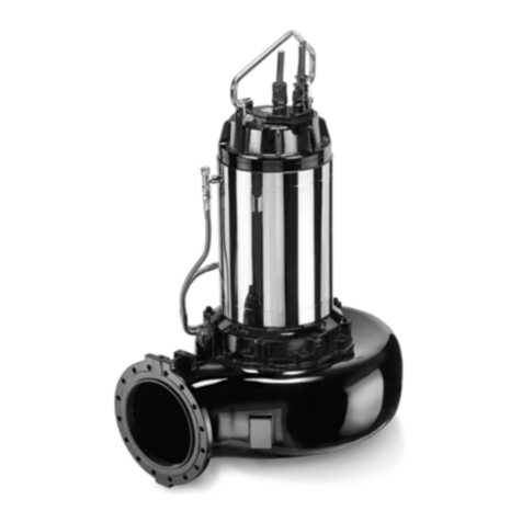
caprari
caprari K M150R Series Use and maintenance instructions
ITT
ITT LN Series Installation,operation and maintenance instruction

Graco
Graco Eagle C Series Instructions-parts list
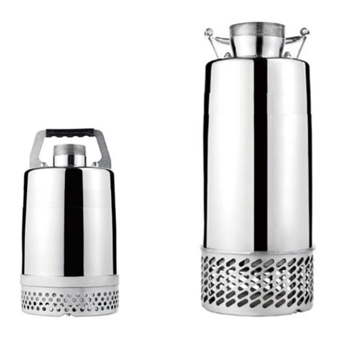
Stancor
Stancor SSDS Series Installation, operation and maintenance manual
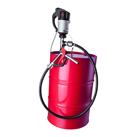
Flux
Flux PTB 11 ATEX 5009 X Original attachment
