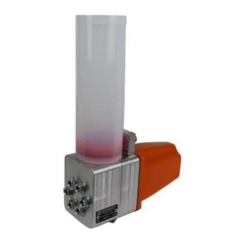
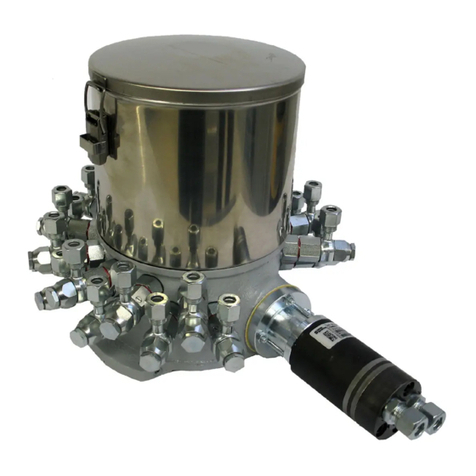
WOERNER GMV-A User manual

Operating manual GMV-A Page 1 of 28 B0803
Piston pump
GMV-A
Translation of the
original operation manual
Version EN 05/2016

Operating manual GMV-A Page 2 of 28 B0803
Translation
With delivery into member countries of the European Community,
this operating manual has to be translated into the user’s language.
If details of the translated operating manual do no coincide with the
original ones, then the original operating manual (German) is to be
referred to for clarification or the manufacturer to be contacted.
Copyright
This document shall neither be transferred to third parties nor cop-
ied. Its content must neither be commercialized nor communicated,
if not explicitly allowed. Violating the before mentioned will cause
claim for indemnification.
All rights reserved.

Operating manual GMV-A Page 3 of 28 B0803
Contents
1. Important information on this operating manual....................................................5
1.1 User .......................................................................................................................5
1.2 Obligation to read...................................................................................................5
1.3 Questions: What to do?..........................................................................................5
1.4 Operating manual...................................................................................................5
1.4.1 Validity ...................................................................................................................5
1.4.2 Content and purpose..............................................................................................5
1.4.3 Site of operation.....................................................................................................6
1.4.4 Meaning of the safety instructions and safety signs................................................6
2. Identification..............................................................................................................7
2.1 Product mark and type designation ........................................................................7
2.2 Product version ......................................................................................................7
2.3 Product denomination ............................................................................................7
2.4 Manufacturer and address......................................................................................7
2.5 Conformity..............................................................................................................7
3. Product description ..................................................................................................8
3.1 Use.........................................................................................................................8
3.2 Limits of application................................................................................................8
3.3 Environmental conditions .......................................................................................8
3.4 Use according to design.........................................................................................9
3.5 Technical data........................................................................................................9
3.5.1 Components...........................................................................................................9
3.5.2 Dimensions ..........................................................................................................10
3.5.3 Technical data......................................................................................................11
3.5.4 Level monitoring F................................................................................................12
3.5.5 Level monitoring F1..............................................................................................12
3.5.6 Function control 1.................................................................................................13
4. Description of function...........................................................................................13
4.1 Drive assembly.....................................................................................................13
4.1.1 Solenoid-based drive assembly............................................................................13
4.1.2 Pneumatic drive assembly....................................................................................13
4.2 Working mode of the version GMV-A ...................................................................13
4.3 Level monitoring F................................................................................................14
4.4 Function control 1.................................................................................................14
5. Safety instructions..................................................................................................14
5.1 Fundamental........................................................................................................14
5.2 Required users‘ skills ...........................................................................................14
5.3 Safety devices......................................................................................................15
5.4 Accident prevention..............................................................................................15
5.5 Residual dangers .................................................................................................15
5.6 Improper use........................................................................................................15
5.7 General safety regulations and duties ..................................................................16
5.8 Exclusion of liability..............................................................................................16
6. Transport, installation, start-up and putting out of operation .............................17
6.1 Transport..............................................................................................................17
6.2 Unpacking............................................................................................................17
6.3 Installation............................................................................................................17
6.4 Power supply and switching-on............................................................................18
6.4.1 Electric drive assembly.........................................................................................18
6.4.2 Pneumatic drive assembly....................................................................................19
6.5 Start-up................................................................................................................19
Operating manual GMV-A Page 4 of 28 B0803
6.6 Putting out of operation ........................................................................................20
7. Operating manual....................................................................................................21
7.1 Trouble shooting, fault eradication........................................................................21
7.2 Replacing the lubricant cartridge..........................................................................22
7.3 Switching-off.........................................................................................................22
8. Cleaning, servicing, fault remedy and repair ........................................................22
8.1 Cleaning...............................................................................................................22
8.2 Maintenance.........................................................................................................23
8.3 Inspection chart....................................................................................................23
8.4 Repair ..................................................................................................................23
8.5 Spare parts list .....................................................................................................23
8.6 Accessories..........................................................................................................24
9. Return to manufacturer ..........................................................................................25
10. Disposal...................................................................................................................27
11. Appendix..................................................................................................................27
11.1 Content of the declaration of harmlessness..........................................................27
11.2 Declaration of Conformity.....................................................................................28

Operating manual GMV-A Page 5 of 28 B0803
1. Important information on this operating manual
This operating manual forms part of the machine and has to be made
available to the operating and maintenance staff at any time.
The safety instructions specified herein have to be obeyed.
If the machine is traded, the operating manual is to be included in the
shipment.
In addition to this operating manual, the current laws and regulations of
the user’s country have to be considered as well, in any case.
1.1 User
This operating manual has been written for technically qualified users, who have been in-
structed or trained for the operation of this product.
1.2 Obligation to read
As owner and user of this unit, you are obliged reading and understanding this operating
manual, in particular the chapter “Safety instructions”. It is your safety that is dealt with. In
case of question and doubt, please get in contact with WOERNER.
1.3 Questions: What to do?
If questions arise, which you cannot solve with this operating manual, do not hesitate to ask
WOERNER for support. In such case, describe the problem as precisely as possible.
1.4 Operating manual
1.4.1 Validity
This operating manual fits to the series design of the unit of type GMV-A. If some sections of
the operating manual refer to some special versions, then it will be especially pointed to.
1.4.2 Content and purpose
This operating manual delivers all the relevant information for start-up, operation and main-
tenance of the unit to assist you to use the unit efficiently as well safely according to its
design and intended purpose of use.

Operating manual GMV-A Page 6 of 28 B0803
1.4.3 Site of operation
Make the operating manual available to the users at their workplace at any time.
1.4.4 Meaning of the safety instructions and safety signs
Safety instructions
The pictograms and warning words used in safety instructions, safety rules and references of
this operating manual do mean:
Danger! Immediately threatening danger that may lead to heavy body
injuries.
Warning! Possibly dangerous situation that may lead to heavy body
injuries.
Caution! Possibly dangerous situation that may lead to slight body
injuries.
Caution! Warning of material damage.
Note! Possibly dangerous situation that may lead to possible damage
to the product or objects in its environment.
Important! Instructions for use and other useful information that facilitate
usage of the product according to its design.
Danger! Immediately threatening danger by electric current that may
lead to heavy body injuries.

Operating manual GMV-A Page 7 of 28 B0803
2. Identification
2.1 Product mark and type designation
Product of the manufacturer Eugen Woerner GmbH & Co. KG
Product type: GMV-A
2.2 Product version
Version from the year of production 2015
2.3 Product denomination
The identification plate has been attached to the side of the pump case and informs
on:
Manufacturer
Type (GMV-A)
No. <order number> (for example, 612345/1)
Year of production
2.4 Manufacturer and address
Eugen Woerner GmbH & Co. KG
Hafenstrasse 2
D-97877 Wertheim
Tel. +49 9342 803 0
Fax +49 9342 803 202
Net www.woerner.de
E-Mail info@woerner.de
2.5 Conformity
The unit meets the provisions as specified in the EC-directive for machines (2006/42/EC).
Declaration of conformity, see annex (chapter 11)

Operating manual GMV-A Page 8 of 28 B0803
3. Product description
3.1 Use
The unit GMV-A has been exclusively designed for the supply of lubri-
cating grease up to the NLGI-class 2.
3.2 Limits of application
The range of application of the components has been limited as follows:
Temperature range: +10 ... +50 °C
According to real version, the application limits can be further restricted. The further re-
strictions are pointed to later in details in this instruction manual.
In addition, the range of application of the unit is determined by the medium to be supplied.
Therefore, to finally define the range of application, consult also the technical data sheets
of the medium to be used.
3.3 Environmental conditions
Operating this unit in aggressive atmosphere (vapour of solvents, acids,
bases, salt water mist, etc.) may cause damage, respectively corrosion
of components and consequently, failure of the equipment and hazards
due to emerging lubricant!
Ambient temperature range
Lower limit temperature: +10 °C
Upper limit temperature: +50 °C
Relative air humidity: max. 70%
Noise level: <70 dB(A)
Physical environment
If the equipment is planned to be operated more than 1,000 m above sea level, consult the
manufacturer, in every case.

Operating manual GMV-A Page 9 of 28 B0803
3.4 Use according to design
The unit must be exclusively used for the supply of lubricating greases (GMV-A) in central
lubricating installations, which the following conditions have to be considered for:
Observance of the safety instructions and safety rules in this operating manual
Compliance with the maintenance and service instructions in this operating manual
Any other usage or any usage beyond the designed one may lead to
heavy personal and material damages.
Forbidden: Supply of gases, liquefied gases, gases solved under pressure,
vapours and other liquids, whose saturation pressure exceeds 0,5 bar above
the normal atmospheric pressure (1013 mbar) at the admissible maximum
temperature, also highly flammable or explosive media as well as foodstuff!
Important! Please consider the safety specifications of the applied sub-
stances as well!
3.5 Technical data
3.5.1 Components
The unit consists of maximum 4 components, which may vary according to the real exe-
cutions:
Pump case
Drive assembly
Cartridge
Level monitoring

Operating manual GMV-A Page 10 of 28 B0803
3.5.2 Dimensions
Level monitoring
GMV-A/M
Magnetic disk
GMV-A/P

Operating manual GMV-A Page 11 of 28 B0803
3.5.3 Technical data
The basic design of the unit consists of the pump case with operating device and connec-
tor to mount a cartridge specified as follows:
Unit:
GMV-A/M
GMV-A/P
Supply rate per stroke
up to 25 mm³
see graph
30 mm³
Number of strokes, max.
120 min-1
120 min-1
Number of outlets
1
1
Control time, min.
0,25 s
0,25 s
Break time, min.
0,25 s
0,25 s
Medium
Grease
NLGI-class 1 and 2
Grease
NLGI-class 1 and 2
Temperature range
+10 … +50 °C
+10 … +50 °C
Cartridge capacity
400 g cartridge
system Lube Shuttle
or
500 g cartridge
system Reiner
400 g cartridge
system Lube Shuttle
or
500 g cartridge
system Reiner
Air pressure
-
3 ... 6 bar
Material
Exterior parts
Zinced steel
and aluminium
Zinced steel
and aluminium
Material
Sealings pump
FPM
FPM
Acceleration, max.
2 x g
2 x g
0
10
20
30
010 20 30 40 50 60
Förderdruck [bar]
Fördervolumen [mm³]
GMV-A/M/../A/..
Supply rate mm3
Supply pressure bar

Operating manual GMV-A Page 12 of 28 B0803
Solenoid:
Rated power Version "A" 30 W
Version "B" 121 W
Duty cycle Version "A" 100%
Version "B" 25%
Amperage
with 24 VDC Version "A" max. 1.27 A
Version "B" max. 5.0 A
Protection class DIN EN 60529 IP65
Insulating material class F
Plug connector DIN EN 175301-803, shape A
Pneumatic drive assembly:
Air pressure
of the drive assembly 3 ... 6 bar
Compressed
air quality according to ISO 554, class 5
3/2-directional control valve:
Power rate 5 W
Relative duty factor 100%
Protection class DIN EN 60529 IP65
Plug connector DIN EN 175301-803, shape BI
Voltage 24 VDC
When connecting inductive or capacitative loads, install proper protec-
tion circuits! (Diode, RC-circuit, varistor)
3.5.4 Level monitoring F
Voltage 10 … 30 VUC
Amperage max. 500 mA
Protection class DIN EN 60529 IP67
Connection Plug connection M8x1, 3-pin
Output NO contact
3.5.5 Level monitoring F1
Voltage 10 … 30 VUC
Amperage max. 100 mA
Protection class DIN EN 60529 IP67
Connection Plug connection M8x1, 3-pin
Output PNP NC contact

Operating manual GMV-A Page 13 of 28 B0803
3.5.6 Function control 1
Voltage 10 … 30 VDC
Load current ≤200 mA
Protection class DIN EN 60529 IP67
Connection Plug connection M8x1, 3-pin
Output PNP NO contact
4. Description of function
4.1 Drive assembly
4.1.1 Solenoid-based drive assembly
The unit is actuated by a d.c. solenoid-based exciter screwed to the pump case. The
solenoid is energised through an external voltage supply.
4.1.2 Pneumatic drive assembly
The unit is driven by a pneumatic piston screwed to the pump case. The piston is actuated
via a flange-mounted 3/2-directional control valve. This 3/2-directional control valve, in turn,
is energised from an external voltage supply.
4.2 Working mode of the version GMV-A
The supply pump consists of
a piston pump, solenoid or
pneumatic drive assembly,
and cartridge.
Intake phase:
The piston is returned by spring
force. In this way, the lubricant
is suctioned out of the cartridge
by the produced vacuum.
Pressure phase:
When energising the solenoid,
respectively actuating the
pneumatic piston, the piston
feeds the lubricant to the outlets through a check valve.

Operating manual GMV-A Page 14 of 28 B0803
4.3 Level monitoring F
At a level monitoring of the cartridge the delivered
package of magnetic disks has to be inserted into
the cartridge between piston follower and compres-
sion spring. The level monitoring is mounted on a
supporting bar. The level monitoring status has to
be evaluated through an external control. Switch
output is an NO contact, closed at minimum level, or
a PNP NC contact, opened at minimum level. In ad-
dition, the "empty"- message is signalled through a
LED attached to the level monitoring device (or with
the NC contact the LED goes off with the “empty”
message or in the event of a wire breakage). The
remaining filling level height, which an error mes-
sage will be released at, can be adjusted (minimum
level height: 20 mm). The connection is made by
means of a plug connection M8x1, 3-pin.
4.4 Function control 1
As a function control, an inductive proximity switch is mounted on the bottom. This proxi-
mity switch controls the piston movement continuously and reports a function failure. Switch
output open at idle position.
The connection is made by means of a plug connection M8x1, 3-pin.
5. Safety instructions
5.1 Fundamental
The unit is shipped from the works in faultless condition and guarantees high technical
safety.
The unit complies with the rules of technology as well as current labour safety and health
protection regulations. There is, however, danger in case of maloperation and abuse for the:
Body and life of both users and third parties,
Unit or other material values of the users, and
Efficient usage of the unit.
5.2 Required users‘ skills
Persons, who work with and on the unit, have to be authorised and instructed by the user
accordingly. They must be able detecting and eliminating possible danger. For that purpose,
knowledge on accident prevention rules, first-aid measures and local rescue equipment is
imperative.
Technically skilled staff properly instructed on the product is allowed to carry-
out inspection, service and maintenance only.

Operating manual GMV-A Page 15 of 28 B0803
Skilled electricians are the only ones allowed to intervene in electrical installa-
tions according to DIN VDE 1000-10.
5.3 Safety devices
The unit is inherently safe due to its design.
The unit must be operated only with the cover of the cartridge closed.
5.4 Accident prevention
Stick to these measured to prevent accidents:
Hinder unauthorised persons from access to the unit.
Keep foreign persons away from dangerous areas and dangerous sites.
Inform repeatedly present foreign persons on residual dangers. As for residual dangers, see
section "Residual dangers".
5.5 Residual dangers
As regards the unit itself, there are no residual dangers for persons and equipment if that unit
is used according to its design as well as intended purpose, and the specified cycles as well
as measures for maintenance and service are kept.
5.6 Improper use
If the unit is used for purposes other than specified and agreed upon, there is
danger for heavy damage to both persons and equipment.
Referring to experience, improper use may include, for example:
Supply of highly flammable or explosive media.
Supply of media, which are able reacting with materials the unit has been made of.
Supply of foodstuff.

Operating manual GMV-A Page 16 of 28 B0803
5.7 General safety regulations and duties
In general, using the unit the following safety regulations and duties are to be
complied with:
Consider the generally accepted rules for labour safety. This is also true,
in addition, for the current basic rules on labour safety and accident pre-
vention on the site of operation.
When used in vehicles, obey to the generally accepted rules and regula-
tions of the Road Code.
As user comply with the regulations for the usage of working equipment.
Operate the unit in clean and faultless state only.
Never remove, modify, bridge or neglect any protection, safety and moni-
toring equipment, in no case.
Do not reconstruct or change the unit.
Report faults or damage to the owner.
Assemble original spare parts only for repair.
The user has to inspect and maintain in good condition all the protection,
safety and monitoring equipment on a regular basis.
After each repair, make sure that the unit is in faultless state and take a
test run.
5.8 Exclusion of liability
If damage to persons, equipment, environment and assets occurs due to ignoring this operat-
ing manual regardless if intentionally or unintentionally, WOERNER shall not be held respon-
sible. No claim for warranty will be accepted. This is also true for any consequential damage.

Operating manual GMV-A Page 17 of 28 B0803
6. Transport, installation, start-up and putting out of operation
6.1 Transport
Transport the unit cautiously to its destination. For that purpose, make use of proper equip-
ment.
6.2 Unpacking
Lift the unit carefully from the packaging and place the unit on a stable as well as plane
support.
Note! Consider that inside the unit and attached components according to
the bill of delivery there might be residues of blue-coloured test oil.
6.3 Installation
The unit is prepared for being mounted on wall or floor by means of two screws M6. The
mounting area has to be that stable to absorb the weight of the unit including the filled
cartridge. In addition, make sure that the mounting surface is vertical and plane.
Drilling pattern for wall mounting: Drilling pattern for floor mounting 1):
1) For bottom mounting the function control of
the piston pump is not possible. In the ver-
sion without function control the plug must
be removed before ground mounting.

Operating manual GMV-A Page 18 of 28 B0803
6.4 Power supply and switching-on
6.4.1 Electric drive assembly
Important! Compare the indications of the local voltage supply with the tech-
nical data of the unit.
Important! Lay the mains cable that way to prevent any unintentional tearing
off.
Important! Skilled electricians are the only ones allowed to intervene in elec-
trical installations according to DIN VDE 1000-10.
Connect the unit to the voltage supply and control.
Before starting-up, double-check the installation for correct electrical connection.
Warning!
There is danger to life when intervening into the electrical installations!
Electrical connecting diagrams
Solenoid A + B 3/2- Vdirectional control valve
Level monitoring F ( )NO contact Level monitoring F1 (NC contact)
Function control 1

Operating manual GMV-A Page 19 of 28 B0803
6.4.2 Pneumatic drive assembly
Important! Compare the indications of the local compressed-air supply sys-
tem with the technical data of the unit.
Important! Lay the pneumatic lines that way to prevent any unintentional
tearing-off.
Connect the unit to the compressed-air supply system and control.
Before starting-up, double-check the installation for correct connection.
6.5 Start-up
The function of the unit was checked in the works. Thus, the unit is ready for use and can be
connected to the local media supply systems.
Important! Consider the safety instructions in section “Power supply and
switching-on”.
First fill lubricant and then start the pump unit, in every case.
The filling level must not be lower than 10-15 mm above the
reservoir’s bottom edge.
Actions to be taken for start-up:
a) Filling the unit with lubricant
Operate the unit with original cartridges only!
Replacement of the cartridge:
Disassembling the empty cartridge:
Press downwards the cover of the cartridge against the spring force and turn it away anti-
clockwise from the bars. Remove the cover slowly to top.
While opening the cover, secure the area between cover and cartridge by
hand to hinder the spring from bouncing out in order to prevent damage
or injury.
Screw off the cartridge from the pump. Remove the magnetic disk and spring from the car-
tridge.
Assembling the cartridge:
Double-check if the mounting thread, magnet and compression spring are suited for
assembly.
Insert the O-ring into the intake borehole of the unit. Screw the air bubble-freely filled car-
tridge into the intake borehole (illustration 1 respectively 2). Press the cover with compres-
sion spring and magnetic disk (illustration 3) against the spring force onto the cartridge,
turn it clockwise to stop on the bars, have the cover completely engaged there and release
it, then.

Operating manual GMV-A Page 20 of 28 B0803
In the cartridge system Reiner (Illustration 2) the follow-up piston has to stand
back 25 mm of the upper rim of the cartridge.
Illustration 1 Illustration 2 Illustration 3
While mounting the cover, ensure the area between cover and
cartridge by hand to hinder the spring from bouncing-out to
prevent damage and injury.
b) Venting of the unit
Vent both the line and unit to get the unit working satisfactorily. For that purpose, actuate
the drive assembly as many times as necessary to have the lubricant emerging at the outlet
without air bubbles.
c) Venting of the line feeding the lubricating point
Make sure that the line feeding the lubricating point has been cleaned and
enables free flow!
Link the line feeding to the lubricating point with the unit, actuate the unit as many times as
necessary to have the lubricant emerging from the line without air bubbles. This action can
be shortened when the tube ascends towards the outlet.
6.6 Putting out of operation
The unit is put out of operation by switching-off and deinstalling from the external power
supply.
System
Lube Shuttle
(400 g)
System
Reiner
(500 g)
This manual suits for next models
2
Table of contents
Other WOERNER Water Pump manuals

WOERNER
WOERNER GMG-B User manual

WOERNER
WOERNER GMF-E User manual

WOERNER
WOERNER GMA User manual

WOERNER
WOERNER GMG-K User manual

WOERNER
WOERNER GMF User manual

WOERNER
WOERNER GFZ User manual

WOERNER
WOERNER GMF-S01 User manual

WOERNER
WOERNER GMV-C User manual

WOERNER
WOERNER GMZ-E User manual

WOERNER
WOERNER PEK User manual
Popular Water Pump manuals by other brands

Water Furnace
Water Furnace GeoLink FC1-GL installation manual

Little Giant
Little Giant FP Series instruction sheet

aqua technix
aqua technix AQUA Plus Series Original installation and operating manual

Flofab
Flofab FGC Series Operation, maintenance & installation manual

Little Giant
Little Giant 5-ASP-LL manual

Little Giant
Little Giant RIM-U owner's manual