Flowtron LeafEater LE-800B User manual

SHREDS LEAVES,
GRASS
CLIPPINGS,
PINE NEEDLES . . .
OWNER’S
MANUAL
MODEL
LE-800B
• Assembly
• Operation
• Maintenance
• Repair Parts
WA R N I N G
Carefully read and
follow safety rules,
precautions and
operating instruc-
tions. Failure to do
so can result in
serious personal
i n j u r y.
Instructions given with this symbol are for per-
sonal safety. Be sure to follow them.
Flowtron Outdoor Products
15 Highland Ave, Malden, MA 02148 • an ARMATRON company
781-321-2300 • www.flowtron.com
F l o w t ron Leaf-Eater One Year Limited Wa r r a n t y
Flowtron, division of Armatron warrants your Leaf-Eater to be free from defects in materials or workmanship under
normal use and service for one year from date of the original purchase. All parts which are defective will be
repaired or replaced free of charge. Any implied warranties, including the implied warranty of merchantability are
also limited in duration for one year from the original purchase date. Some states do not allow limitations on how
long an implied warranty lasts, so the above limitations may not applyto you.
The provisions of this warranty shall not apply to any Leaf-Eater which has been subject to misuse, neglect or
accident, nor which is used for a purpose for which it is not designed, or which shall have been repaired or altered
in any way so as to adversely affect its performance and reliability. Service by unauthorized parties voids your
warranty. Warranty covers only the original purchaser. Commercial and/or professional use is excluded from war-
ranty coverage.
Flowtron neither assumes nor authorizes any person to assume for it any other liability in connection with its prod-
ucts. No responsibility is assumed for any consequential damages that may result from the use of a Flowtron
product, not for damages due to accident, abuse, lack of responsible care, the affixing of any unauthorized attach-
ments, loss of parts or subjecting this unit to any but the specified voltage. Some states do not allow the exclusion
or limitation of the incidental or consequential damages, so the above limitation or exclusion may not apply to you.
This warranty gives you specific legal rights, and you may also have other rights which vary from state to state.
Flowtron Outdoor Products, 15 Highland Ave., Malden, MA 02148 • an ARMATRON company
A lw ays Wear Eye Protection During Operation

page 2
A . I n t r o d u c t i o n
Your Flowtron Leaf-Eater is a quality built product
that is designed to provide you with a unit that is not
only affordable, but will perform with a minimum of
care and maintenance.
Special Features Include:
• Powerful universal electric motor
• Runs on normal household current
• Easily moved from place to place
• Can be used on a container or free standing on
its own legs (included with unit)
• Easily replaceable cutting cords with extras sup-
plied with each unit.
B . U n p a cking Instructions
Your unit has been carefully packed at the factory to
prevent damage during shipment and storage.
Carefully unpack the carton as follows:
1.Remove contents from carton
2.Check parts against list shown.
3.Examine for damage
KNOW YOUR FLOWTRON LEAF-EATER
C a r ton Contents
Key # D e s c r i p t i o n Q t y.
1F u n n e l 1
2 Upper Housing 1
3 Lower Housing Assembly 1
4Legs 3
5 Hardware Package 1
6Owner’s Manual 1
R E A R
L E F T S I D E
4
2
1
5
R I G H T S I D E
6
FIGURE 2
3
F R O N T
ASSEMBLY
H a rdware Bag Contents:
Q t y.D e s c r i p t i o n Looks Like
3Container Mounting Bracket
3Stud Plate
2 Screw, Pan Head, 10-32 x 3/8”
3 Screw, Sht. Mtl., #10 x 5/8”
4 Screw, Sht. Mtl., #10 x 1/2, Blk.
8Hex Nut, Self-Lock, 10-32
4 Washer, #10
3 Tinnerman Clips
3Leg Caps
36 Cutting Lines
A . Preparation
Your owner’s manual has been developed to help
you assemble the unit and to understand its safe
operation. It is important that you read your manual
completely to become familiar with the unit before
you begin assembly.
1. Read your owner’s manual
2. Tools you will need:
#2 Phillips Head Screwdriver
3/8” Nut Driver
page 3
ASSEMBLY (continued)
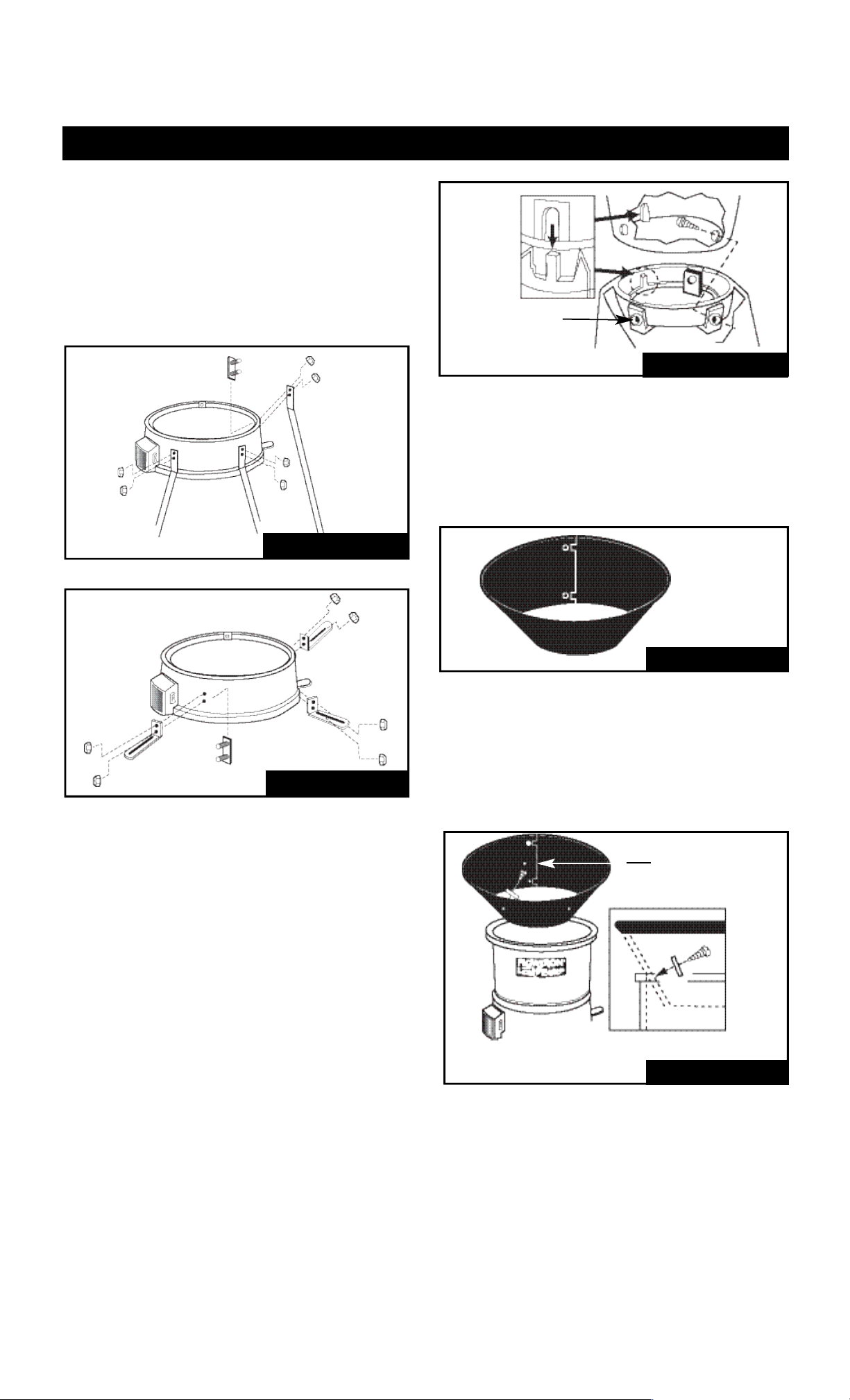
1 . A s s e m b ling Legs or Mounting Brack e t s
To install the three legs or the three mounting
brackets, align the three stud plates with the six
mating holes in the lower housing. Fasten the legs
or brackets with the six #10 - 32 self-locking hex
nutsas shown in Figures #3 or #4. When using
the legs,slip the three leg caps onto the end of
each leg.
2 . A s s e m b le Upper and Lower Housing
Install the three Tinnerman Clips onto the edge of
the Lower Housing in areas provided. Place both
Upper Housing and Lower Housing upside down
and align the slot in the edge of the Upper Housing
with the tab on the Lower Housing. Push the Lower
Housing down until it is seated firmly in the Upper
Housing. Position the assembly in the upright posi-
tion and fasten both housings together using the
three #10 x 5/8” sheet metal screws as shown in
Figure #5.
TINNERMAN CLIP
(THREE PLACES)
FIGURE 5
FIGURE 6
3 . A s s e m ble Funnel
Assemble funnel with tabs on outside and screw
together in two places using 10-32 x 3/8” screws
and 10-32 hex nuts. Place screw heads on inside
with nuts on outside.
4 . A t t a c h Funnel to Upper Housing
Align four (4) holes in Funnel with four holes in
Housing and fasten securely using four #10 x 1/2”
screws and #10 flat washer as shown in cutaway
view in figure 7.
#10 X 1/2" SCREW
AND #10 FLAT
WA S H E R
FIGURE 7
FIGURE 3
FIGURE 4

1 . Become familiar with all sections of this owner’s
manual before attempting to operate the shredder.
This shredder should be used solely for the pur-
pose it was intended.
2 . Use only parts or accessories specifically designed
for use with this shredder. Using other parts or
accessories could increase risk of injury.
3 . Keep Children Away – all visitors should be kept at
a distance from the work area.
4 . Never allow your hands or any part of your body or
clothing inside the upper housing area.
5 . Avoid DangerousEnvironments – do not use
shredder in damp or wet locations. Do not operate
or store shredder in wet areas. Do not operate in
rain. Store indoors when not in use, in a dry, and
high or locked-up place — out of reach of children.
6 . This shredder should be operated on a solid, level
s u r f a c e .
7 . Dress Properly – do not wear loose clothing or
j e w e l r y. They can be caught in moving parts. Use
of work gloves and substantial footwearis advised
when working outdoors. Wear protective hair cov-
ering to contain long hair.
8 . Stay Alert – Watch what you are doing. Use com-
mon sense. Do not operate shredder when you are
t i r e d .
9 . Do not Abuse Power or Extension Cords – Never
carry unit by its power cord or yank cord to discon-
nect from receptacle. Keep all cords clean and
away from heat, oil and sharp edges and inspect
for damage before each use.
1 0 . Ground unit properly. Follow instructions on page 7
when connecting to electrical outlet.
11 . Warning – To reduce the risk of electrical shock,
use only an extension cord intended for outdoor
use. See page 7 for additional information on
extension cords.
1 2 . Ground fault circuit interrupter (GFCI) protection
should be provided on the circuit(s) or outlet(s) to
be used for this shredder. Receptacles are avail-
able having built-in GFCI protection and may be
used for this measure of safety.
1 3 . If it is necessary for any reason to inspect, clean or
repairthe shredder, turn the shredder off and wait
until it comes to a complete stop, then disconnect
the power cord before attempting such inspection
or repair.
1 4 . Disconnect shredderfrom the power source when
not in use, before servicing, and when changing
cutting lines.
1 5 . When feeding material into the shredder be
extremely careful that pieces of metal, rocks, bot-
tles, cans or other foreign objects are not included.
1 6 . Do not force the shredder. It will do the job better
and with less likelihood of a risk of injury when
used at the rate for which it was designed.
1 7 . If the cutting mechanism strikes a foreign object or
if your shredder should start making an unusual
noise or vibration, immediately switch it off, wait
until the shredder has come to a complete stop,
then disconnect the power cord and take the fol-
lowing steps:
A. Remove any foreign or clogged material.
B. Check for any loose parts and tighten to
assure continued safe operation
C. Replace or repair any damaged parts.
1 8 . Avoid unintentional starting. Be sure switch is off
when plugging in the shredder.
1 9 . Always use safety glasses and face or dust mask if
operation is dusty.
2 0 . Check discharge area periodically after stopping
shredder to assure the processed material does
not build up and clog motor cooling vents.
2 1 . Do Not Overreach – keep proper footing and bal-
ance at all times.
2 2 . Do not move shredder when motor is running or
with finger on the switch.
2 3 . Maintain Shredder With Care – Follow instructions
for replacing cutting lines and for cleaning air fil t e r.
Inspect shredder power cord periodically, and if
damaged, have it repaired by an authorized serv-
ice facility. Keep handles dry, clean, and free from
oil and grease.
2 4 . Check Damaged Parts – Before further use of the
s h r e d d e r,any part that is damaged should be
carefully checked to determine that it will operate
properly and perform its intended function. Check
for alignment of moving parts, binding of moving
parts, breakage of parts, mounting, and anyother
condition that may affect its operation. A guard or
other part that is damaged should be properly
repaired or replaced by an authorized service cen-
ter unless indicated elsewhere in this manual.
SAFETY RULES AND PRECAUTIONS
Wa r n i n g : To reduce the risk of fir e , electric shock , and personal injury, the fo l l o w i n g
basic safety precautions should alw a ys be fo l l ow e d .
READ ALL INSTRUCTIONS
S AVE THESE INSTRUCTIONS
page 4
page 5
1 . On/Off Switch
The On/Offswitch is located on the side of the
Lower Housing. To turn unit on push switch to “On”
position, see figure 10. To turn unit “Off” push switch
down to “Off” position, see figure 10.
2 . C i r cuit Breaker/Reset Button
The circuit breaker/reset button is located on the
l o w e r, outside front of the motor housing as shown
in figure 10. The unit is designed to shut down in
the event of an overload. To restart, place on/off
switch in “off” position, push reset button, wait
approximately three minutes and then place switch
in “ON” position.
ELECTRICAL REQUIREMENTS
I m p o r t a n t : Use a 14 ga. or heavier extension cord with a maximum length of 100 ft.
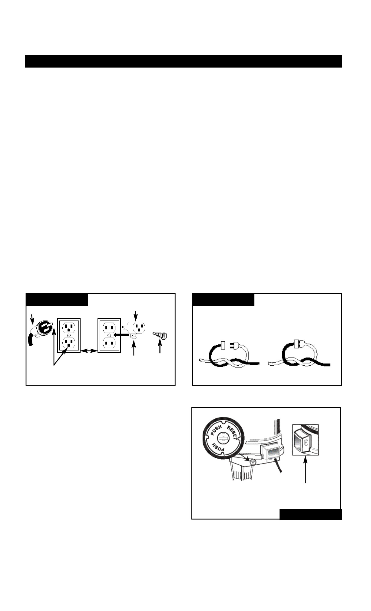
G r ounding Instructions
This shredder should be grounded while in use to
reduce the risk of electric shock to the operator.
The shredder is equipped with a three-conductor
cord and three-prong grounding plug. The green or
green and yellow conductor in the cord is the
grounding wire. Never connect the green or green
and yellow wire to a live terminal.
The shredder is intended for use on a circuit that
has a grounded outlet box that looks like the one
illustrated in figure 8, sketch A .
An adapter which looks like the adapter illustrated
in figure 8, sketch B is available for connecting
three-prong plugs to two-prong receptacles. T h e
green colored rigid ear, lug, or the like on the
a d a p t e r, must be connected to a permanent
ground, such as a properly grounded outlet box,
using a metal screw.
Check with a qualified electrician or serviceman if
the grounding instructions are not completely
understood, or if in doubt as to whether the shred-
der is properly grounded.
Extensions Cord s
Only use three-wire extension cords that have
three-prong grounding plugs and three-hole recep-
tacles that accept the shredder’splug. When using
an extension cord, make sure that it is in good con-
d i t i o n .
Use a 14 ga. or heavier extension cord with a max-
imum length of 100 ft. An undersized extension
cord will cause a drop in line voltage resulting in
lossof power and overheating.
Warning – To reduce the risk of electric shock, only
use extension cords intended for outdoor use, such
as cord types SW-A, SOW- A ,
S T W -A, STO W -A, SJW-A, SJOW-A, SJTW- A o r
S J T OW -A.
To prevent disconnection of the shredder cord from
the extension cord during operation, make a knot
as shown in figure 9. Devices for retaining exten-
sion cords are also available at your local hardware
r e t a i l e r.
FIGURE 8 FIGURE 8
G ROUNDING METHOD
( A )
G R O U N D I N G
P I N
P L U G
L U G M E TA L
S C R E W
A D A P T E R
( B )
COVER OF
G R O U N D E D
O U T L E T B O X
METHOD OF SECURING EXTENSION CORD
( B )
E X T E N S I O N
C O R D
TIE CORD AS SHOW
C O N N E C T PLUG & RECEPTA C L E
S H R E D D E R
C O R D
( A )
MOTOR INFORMATION
FIGURE 10
O N / O F F
S W I T C H
C I R C U I T B R E A K E R /
R E S E T S W I T C H
page 6
SAFE OPERATING INSTRUCTIONS
Disconnect power cord from extension cord
before moving machine from one location to
another location.
C AU T I O N
Your Flow t ron Leaf-Eater can be hazardous if impro p e r l y or carelessly used.
The instructions and figures shown below demonstrate the right way to use your mach i n e.
Read and understand the operating instructions before you operate your mach i n e .A l w a ys use
s a f e and cautious operating methods.
Please remember the operating and safety instructions have been written for your use. Fa i l u r e
to read all instructions may result in injury.
Be sure you have read “Rules for Safe Operation” b e f ore pro c e e d i n g .
1 . M o ving Your Unit
Disconnect the power cord from the extension
cord or power source, grasp the unit along the
ridge on the Upper Housing, liftand move to wher-
ever you choose.
Wear Safety Glasses when operating this
machine.
C AU T I O N
Do not operate your machine without the funnel
a t t a c h e d .
C AU T I O N
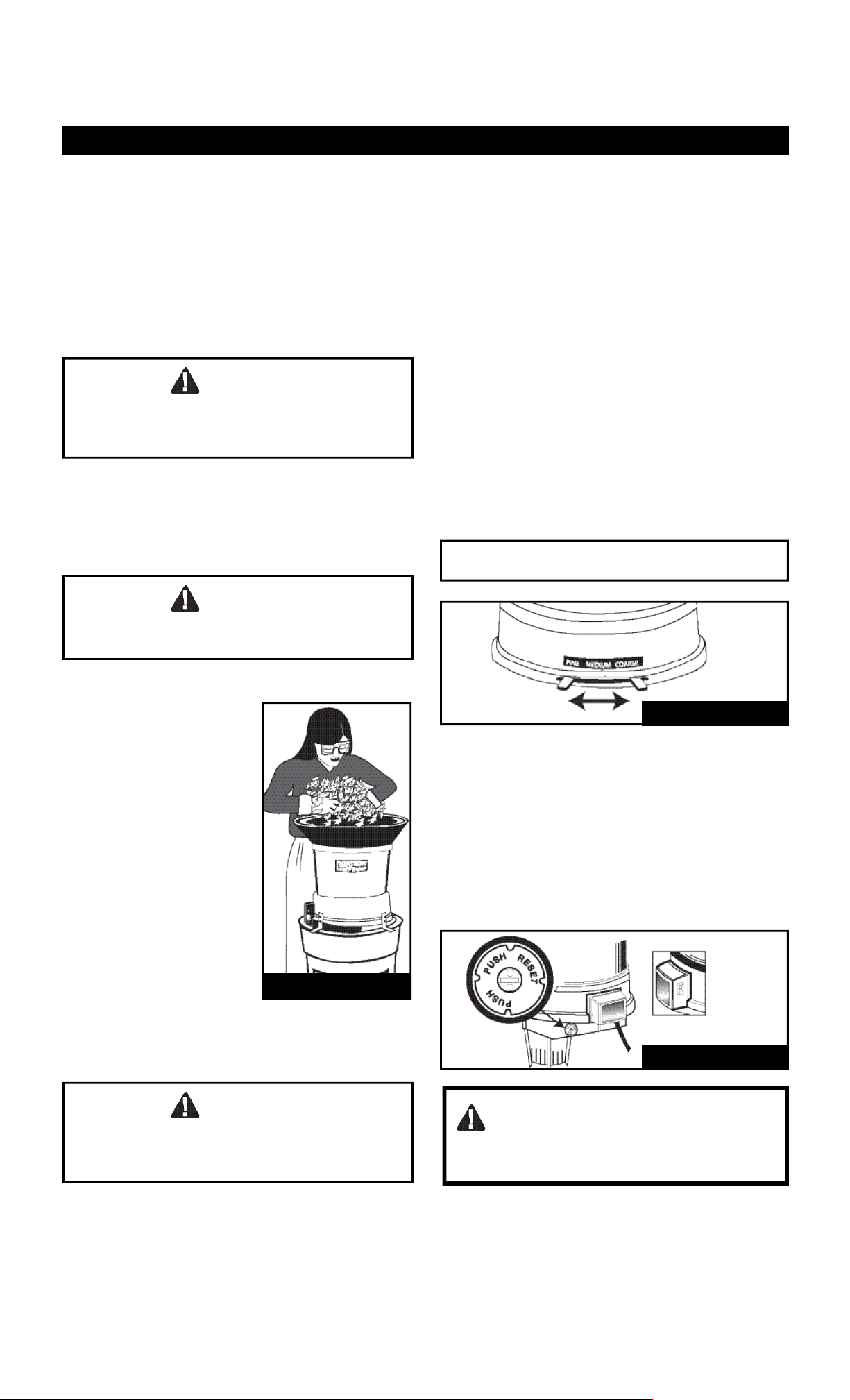
2 . Loading Your Mach i n e
With the machine running,
feed double handfuls of dry
leaves, or single handfuls
of wet leaves,into the hop-
p e r. Allow the machine to
shred the load completely
and regain speed before
reinserting the next load.
Do not overload the
machine by letting it labor
at low speed: this will
cause the circuit breaker to
shut the motor off. If this
happens, turn the switch
o f f, unplug the machine,
clear the unshredded
material from the hopper,
reset the breaker and continue
with your shredding.
FIGURE 12
3 . M u l c hing Control Lev e r
The Control Lever, see figure 12, controls the parti-
cle size and speed at which material goes through
the unit. With the Control Lever in the Coarse posi-
tion, material will process through the unit faster but
will give you a larger particle size than if the lever
were in the Fine position. The Fine position setting
will discharge material slower but will give the small-
est particle size.
F i n e : 3 0 - 1 M e d i u m : 1 5 - 1 C o a r s e : 8 - 1
Do not allow shredded material in trash
container or leaf bag to reach bottom of
motor housing. A reduction in airflow will
result and may cause permanent dam-
age to your motor
4 . C i r cuit Breaker
This machine is equipped with a circuit breaker that
is designed to shut off the machine in the event of
an overload. To restart your machine after the circuit
breaker activates,place On/Offswitch to the “Off ”
position, push in on the Reset Button, figure 13,
and wait for approximately three minutes. A f t e r
three minutes place the On/Off switch to the “On”
position and continue to operate.
FIGURE 13
FIGURE 11
page 7
MAINTENANCE
Disconnect power cord from power source
before attempting any maintenance.
C AU T I O N
1 . Cleaning Your Unit
Your unit requires a minimum of maintenance other
than cleaning. It is recommended that you clean out
built-up residue from inside the Housing area, and
from between Mulching Discs during and after each
use. Also tighten all nuts, boltsand screws periodi-
c a l l y.Replace cutting line as often as necessary,
see below, and clean Air Filter frequently, see fig u r e
15. Any other maintenance or repairs should be per-
formed by an authorized Flowtron Service Station.
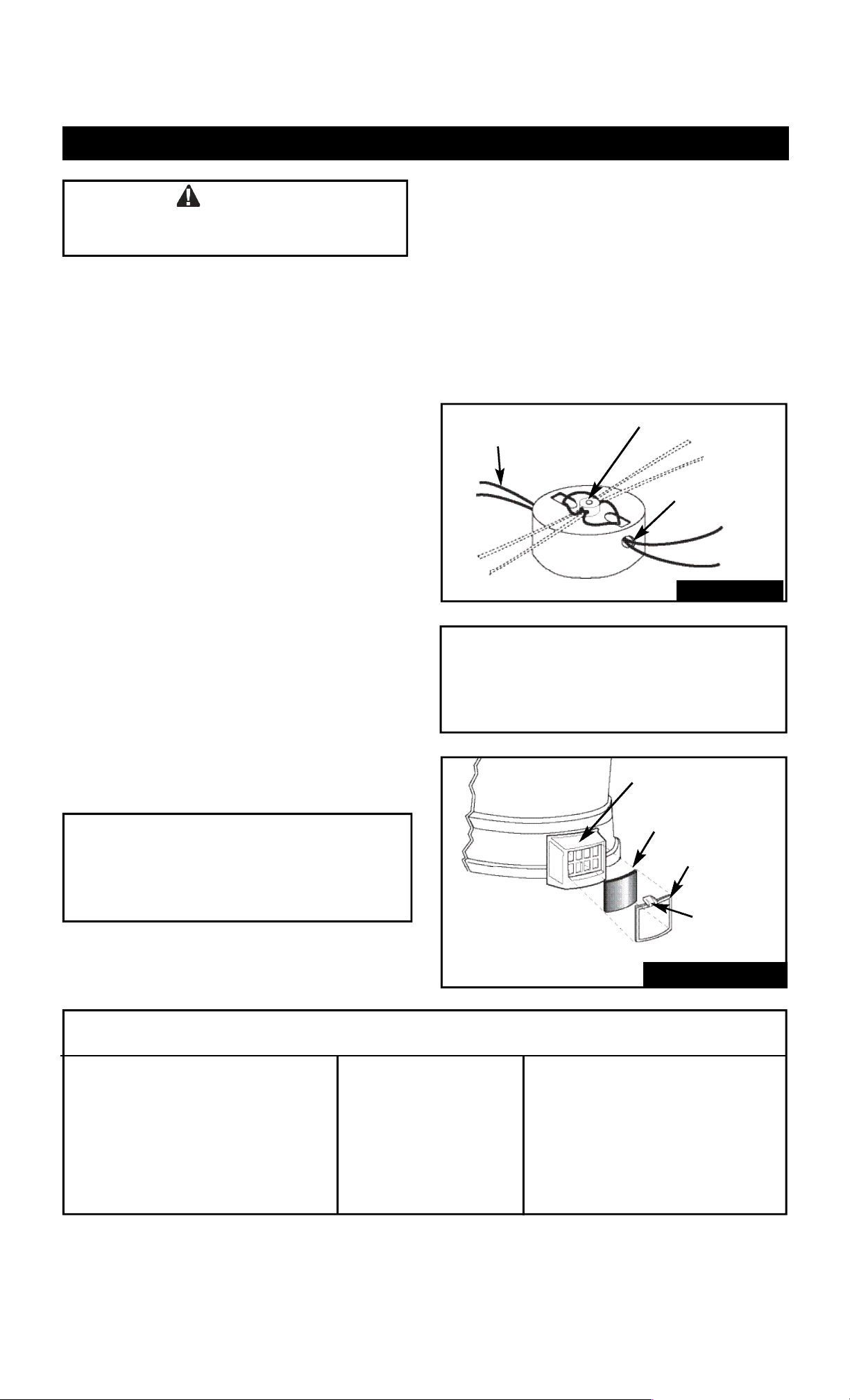
2 . R e m o val/Replacement of Cutting Line
Your unit is supplied with six strips of six (6) cutting
lines each (for a total of 36 cutting lines). To separate
individual lines simply pinch the indent between lines
nearest strip end and peel away.
Replace cutting cord when a noticeable decrease in
shredding efficiency is observed. To remove used
cutting lines pull used line out of the spinner head
inside the housing. To install new cutting lines place
each end of new line through the two holes in the
post on top of the spinner head and pull through so
that both ends of the line are even. Thread lines
through the two ferrules on the side of the spinner
head and pull tight so that ends are even.
See figure 14.
WARNING: Use only .080 diameter monofilament
cord 12 3/4" long. Use of thicker lines, lines made
of substitute materials, or lines greater than 12 3/4"
long MAY RESULT IN PERMANENT DAMAGE TO
YOUR MOTOR AND/OR INJURY.
Tro u b le Shooting
S y m p t o m P r o bl e m C o r r e c t i o n
Motor will not start No electric power. Check to be sure power cord is connected to
the power source.
Circuit breaker has tripped. Clean filter and residue inside housing.
No cutting action. Cutting line is worn or residue Replace cutting line with new line.
is built-up inside of housing. Clean out built-up residue in housing.
Motor does not sound like it is running properly. Air filter is dirty. Remove and clean air filter.
Circuit breaker trips. Unit bound with debris. Clean unit.
N o t e : LER-100 Cutting Line Kit for model
LE 800 contains 12 replacement lines and may be
purchased from your local dealer.If not available,
order direct from Flowtron Outdoor Products or on
line at w w w. flow t ro n . c o m .
3 . R e m o val/Cleaning Air Filter
The Air Filter is located on the side of the Lower
Housing by the On/Off switch. To remove push down
and out on the tab on top of the Filter Cover, see fig-
ure 15. Remove Air Filter and rinse with clear water
and air dry. Replace Air Filter before using machine.
I m p o r t a n t
Do not attempt to run or use your machine with
the Air Filter removed. Check frequently to
insure that the Air Filter is clean. Always discon-
nect the power cord prior to removing Air Filter.
FIGURE 15
AIR FILTER HOUSING
AIR FILTER ELEMENT
air filter cover
TAB: PUSH
DOWN A N D
O U T
B O T H E N D S
M U S T B E E V E N
P U T T H R O U G H
F E R R U L E H O L E
T H R E A D T H R O U G H TO P H O L E
FIGURE 14
357 3389 REV 5
page 8
2 1
1 7
1 8
2 4
1 9
2 0
4
2 3
2 2
1 6
1 5
1 4
1 2
3 6
3 9
3 8
2 6
2 7
4 0
2 9 3
3 0
1 2
1 3
3 1
3 7
3 2
4
4 2
3 4
3 5
1 0
11 9
8
7
1 8
W H I T E
G R E E N
2 5
3 3
4 1
1 2
3 3
2 8 5
6
3 5
2 8
2 0
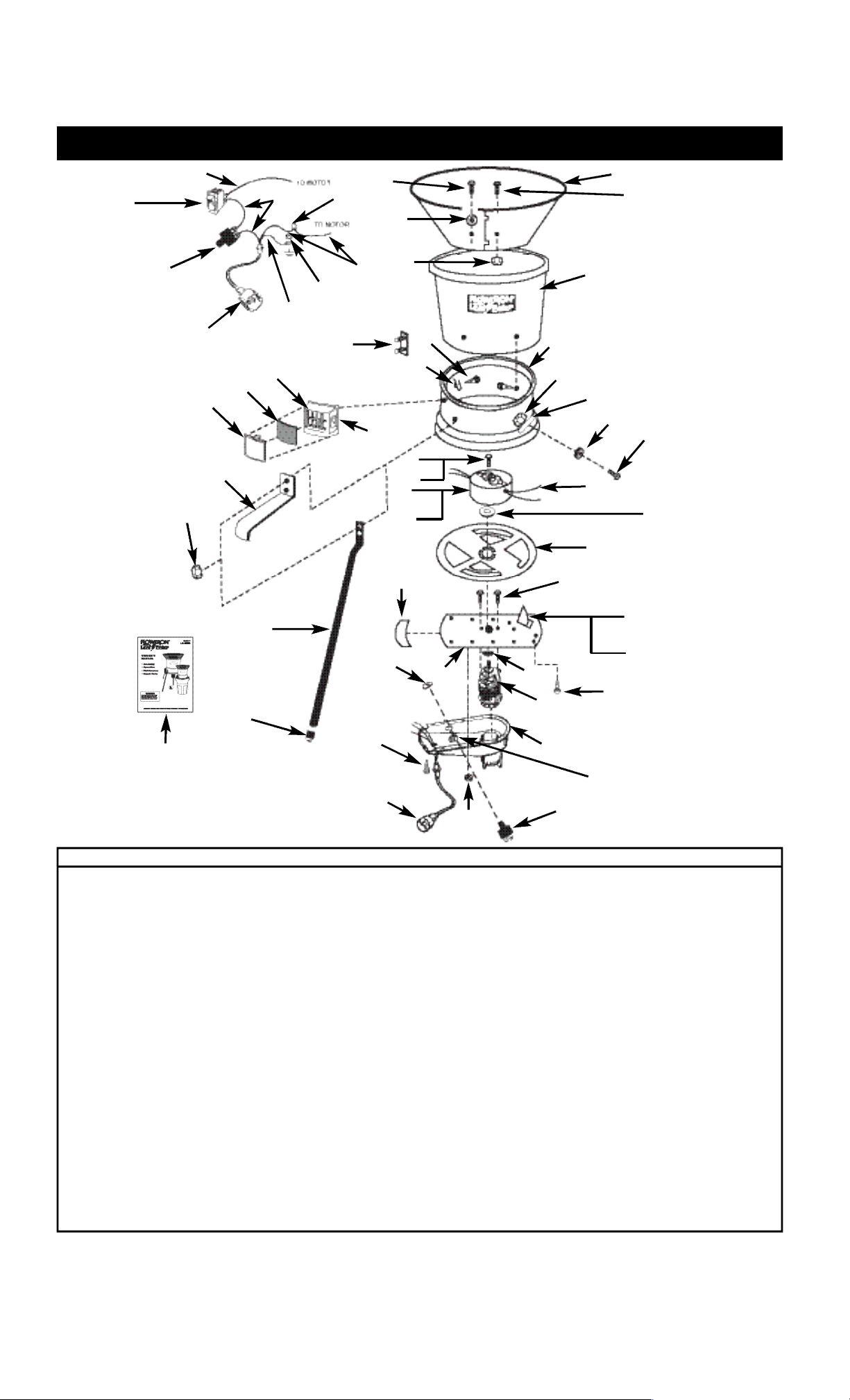
Ref. # Part # Description Qty.
1 355 1672 F U N N E L 1
2 245 6237 P40 S C R E W, SHT. MET., PAN HD., PHIL, #10 x 1/2, BLK. 4
3 355 3103 DISK SUPPORT 3
4 245 6269 P06 HEX NUT, 10-32, SELF-LOCK 8
5 245 6225 P51 S C R E W, PAN HD., PHIL, BLACK, 10-32 x 3/8 2
6 355 1305 UPPER HOUSING 1
7 345 1316 TINNERMAN CLIP 3
8 245 6236 P41 S C R E W, SHT. MTL. #10 x 5/8” 3
9 305 3530 LOWER HOUSING A S S Y. 1
1 0 396 2877 p01 CUTTING LINE 2
11 305 3399 STUD PLAT E 3
1 2 245 6269 P33 HEX NUT, 10-32, BLACK, SELF-LOCK 11
1 3 345 2978 S C R E W, PHIL, HD, #10-24 x 3/8 2
1 4 368 3392 P1 L E G 3
1 5 352 3430 PL5 C O N TAINER MOUNTING BRACKET 3
1 6 596 494LEG CAP 3
1 7 355 3105 S PACER, CIRCUITB R E A K E R 1
1 8 394 3511 C I R C U I T B R E A K E R 1
1 9 367 1429 P01 M O T OR PLATE SEAL 1
2 0 312 2517 POWER CORD 1
2 1 355 2062 M O T OR DUCT 1
Ref. # Part # Description Qty.
2 2 345 3501 PA N E L N U T, CIRCUITB R E A K E R 1
2 3 379 3449 M O T O R 1
2 4 305 3395 MOUNTING PLATE A S S E M B LY, MOTO R 1
2 5 566 399 P O P R I V E T, 1/8” 2
2 6 355 3096 MULCHING DISC 1
2 7 305 1779 SPINNER HEAD A S S E M B LY 1
2 8 394 3014 SWITCH, ON/OFF 1
2 9 355 1304 F I LTER COVER 1
3 0 367 1884 F I LTER ELEMENT 1
3 1 355 1303 F I LTER HOUSING 1
3 2 595 1506 WIRE NUT 1
3 3 245 6245 P28 S C R E W, SHT. MET., HEX HD., #8 x 1/2” 3
3 4 245 6225 P54 S C R E W, PAN HD., PHIL, BLACK 10-32 x 3/4” 3
3 5 245 6272 P24 F L AT WASHER, BLACK, #10 7
3 6 345 3512 NYLON SCREW 1
3 7 352 3149 C U T OFF BLADE 1
3 8 345 1683 JAM WASHER, SPINNER 1
3 9 567 4675 “O” RING (NOTS H O W N ) 1
4 0 369 1689 I N S E R T, SPINNER (NOTS H O W N ) 1
4 1 567 9929 “O” RING 1
4 2 357 3389 OWNER’S MANUAL 1
FLOWTRON EXPLODED VIEW OF LE-800B
B L AC K
W H I T E
21
Table of contents
Popular Paper Shredder manuals by other brands

Royal
Royal 112MX Operation manual

WHITAKER BROTHERS
WHITAKER BROTHERS intimus 26SC2 operating instructions

SEM
SEM 2226 Series Operation and maintenance manual

Intimus
Intimus 240 Crusher operating instructions

UNITED OFFICE
UNITED OFFICE UAV 150 A1 - 5 operating instructions

Fellowes
Fellowes POWERSHRED 90S instructions

UNITED OFFICE
UNITED OFFICE UAV 380 A1 - 2 operating instructions

KRUG+PRIESTER
KRUG+PRIESTER IDEAL 2604 operating instructions

Fellowes
Fellowes DS-3 user manual

Fellowes
Fellowes POWERSHRED 90S instructions

UNITED OFFICE
UNITED OFFICE UAV 190 B2 operating instructions

Techko
Techko AUTOTECH HAF080 Operation instructions


