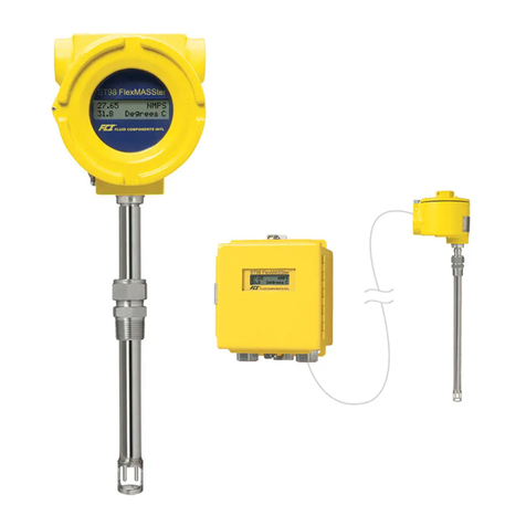
Fluid Components Intl ST51A Manual

Doc. No. 06EN003426 Rev. C

06EN003426 Rev. C ST51A/ST75A/ST75AV Mass Flow Meters
Fluid Components International LLC
Notice of Proprietary Rights
This document contains confidential technical data, including trade secrets and proprietary information which is the property of Fluid Components
International LLC (FCI).Disclosure of this data to you is expressly conditioned upon your assent that its use is limited to use within your company
only (and does not include manufacture or processing uses). Any other use is strictly prohibited without the prior written consent of FCI.
© Copyright 2019by Fluid Components International LLC.All rights reserved. FCI is aregistered trademark ofFluid Components International LLC. Information subject to change without notice.

ST51A/ST75A/ST75AV Flow Meters 06EN003426 Rev. C
Fluid Components International LLC iii
Table of Contents
Table of Contents......................................................................................................................................................................................iii
List of Figures ..........................................................................................................................................................................................vii
List of Tables...........................................................................................................................................................................................viii
1GENERAL.........................................................................................................................................................................................1
Product Description...........................................................................................................................................................................1
Theory of Operation..........................................................................................................................................................................1
Safety Instructions.............................................................................................................................................................................1
Order Verification..............................................................................................................................................................................1
Hardware – Model Descriptions................................................................................................................................................2
Optional Accessories ................................................................................................................................................................2
Specifications....................................................................................................................................................................................3
2INSTALLATION.................................................................................................................................................................................5
Instrument Identification and Outline Dimensions.............................................................................................................................5
Pre-Installation..................................................................................................................................................................................5
Serial Number...........................................................................................................................................................................5
Flow Direction Alignment ..........................................................................................................................................................5
Recommended Straight Run.....................................................................................................................................................7
Installing ST51A Flow Element.........................................................................................................................................................7
Compression Fitting Mounting ..................................................................................................................................................7
Retractable Packing Gland Mounting........................................................................................................................................9
Retraction/Removal Procedure.......................................................................................................................................10
Installing ST75A/ST75AV Flow Element.........................................................................................................................................11
Pipe Tee Installation................................................................................................................................................................11
Tube Tee Installation...............................................................................................................................................................11
NPT Flow Tube Installation.....................................................................................................................................................11
Flanged Installation.................................................................................................................................................................11
Re-positioning the Display..............................................................................................................................................................11
Installing the Remote Flow Meter System.......................................................................................................................................12
Remote Cable.........................................................................................................................................................................13
Local Enclosure.......................................................................................................................................................................14
Remote Enclosure...................................................................................................................................................................15
Instrument Wiring............................................................................................................................................................................17
Accessing the Interface Board Connection Terminals............................................................................................................18
ESD Precautions.............................................................................................................................................................18
Interface Board Connections...................................................................................................................................................19
Power Connections.........................................................................................................................................................19
Signal Connections.................................................................................................................................................................21
4-20 mA Analog Outputs.................................................................................................................................................21
HART Connections..........................................................................................................................................................22

06EN003426 Rev. C ST51A/ST75A/ST75AV Mass Flow Meters
iv Fluid Components International LLC
Pulse Output and Alarm (Source/Sink)...........................................................................................................................23
Modbus Connections.......................................................................................................................................................24
Serial Interface Connector J9..................................................................................................................................................25
3OPERATION...................................................................................................................................................................................27
Overview.........................................................................................................................................................................................27
Instrument Configuration and Setup Using the Service Port (RS-232)...........................................................................................27
Main Menu ..............................................................................................................................................................................28
Top Level Menu Commands...................................................................................................................................................28
Secondary Commands: CLI....................................................................................................................................................28
Start-up and Commissioning...........................................................................................................................................................28
Z Menu: Configure Flow Units and 4-20 mA Output Scaling ..........................................................................................................29
Changing Flow Units, Example...............................................................................................................................................30
V Menu: Configure Outputs (4-20 mA and Source/Sink Outputs)...................................................................................................30
4-20 mA Configuration............................................................................................................................................................32
Flow/Temperature Assignment.......................................................................................................................................32
NAMUR Mode.................................................................................................................................................................32
HART Damping Value.....................................................................................................................................................32
Source/Sink Output Configuration...........................................................................................................................................32
Source/Sink Output Functions.........................................................................................................................................32
Source/Sink Output Programming Parameters...............................................................................................................32
Serial Interface Command Reference.............................................................................................................................................33
Top Level Menu Commands...................................................................................................................................................33
CLI Commands.......................................................................................................................................................................34
HART Operation..............................................................................................................................................................................36
Process Data Operation..........................................................................................................................................................36
ST51A/ST75A/ST75AV HART Process Data Organization....................................................................................................36
ST51A/ST75A/ST75AV Process Variable Slots..............................................................................................................36
Primary Variable Classifications......................................................................................................................................36
Device Description Files..........................................................................................................................................................36
EDDL Files......................................................................................................................................................................37
Loading the DD Files to the 475 Field Communicator ............................................................................................................37
Service Data Operation...........................................................................................................................................................37
HART Command List Reference.....................................................................................................................................................40
ST51A/ST75A/ST75AV HART Universal Commands.............................................................................................................40
ST51A/ST75A/ST75AV HART Common Practice Commands...............................................................................................47
ST51A/ST75A/ST75AV HART Device Specific Commands...................................................................................................49
HART Command Bit Assignments..........................................................................................................................................52
Command Status Bytes...................................................................................................................................................52
Command 48, Additional Device Status Bytes................................................................................................................54
HART Engineering Units Codes..............................................................................................................................................55

ST51A/ST75A/ST75AV Flow Meters 06EN003426 Rev. C
Fluid Components International LLC v
Modbus Operation...........................................................................................................................................................................56
Setting Up the ST51A/ST75A/ST75AV for Modbus Operation...............................................................................................56
ST51A/ST75A/ST75AV Modbus Commands..........................................................................................................................57
ST51A/ST75A/ST75AV Process Data Registers....................................................................................................................57
Totalizer Register Description.................................................................................................................................................58
ST51A/ST75A/ST75AV Modbus Service Registers................................................................................................................59
Examples of Totalizer Service Register Access using ModScan32........................................................................................59
Checking the Totalizer Value..........................................................................................................................................59
Resetting the Totalizer Value..........................................................................................................................................61
Starting/Stopping the Totalizer Count .............................................................................................................................61
Checking K Factor Values...............................................................................................................................................62
Changing/Setting K Factor Values..................................................................................................................................62
Modbus Engineering Units Codes Table.................................................................................................................................64
Modbus Device Status Code Table.........................................................................................................................................64
4MAINTENANCE..............................................................................................................................................................................65
Calibration.......................................................................................................................................................................................65
Electrical Connections.....................................................................................................................................................................65
Remote Enclosure...........................................................................................................................................................................65
Electrical Wiring ..............................................................................................................................................................................65
Flow Element Connections.............................................................................................................................................................65
Flow Element Assembly..................................................................................................................................................................65
5TROUBLESHOOTING....................................................................................................................................................................67
Application Verification....................................................................................................................................................................67
Equipment Needed.........................................................................................................................................................................67
Check Serial Numbers....................................................................................................................................................................67
Check the Instrument Installation....................................................................................................................................................67
Check for Moisture..........................................................................................................................................................................67
Check Application Design Requirements........................................................................................................................................67
Verify Standard Versus Actual Process Conditions........................................................................................................................67
Verifying Calibration Parameters (Diagnostics)..............................................................................................................................68
Hardware Verification......................................................................................................................................................................69
Fuse Check.............................................................................................................................................................................69
Sensor Check..........................................................................................................................................................................69
Transmitter Circuit Calibration Check (Delta R Verification)...........................................................................................................70
References..............................................................................................................................................................................70
Equipment...............................................................................................................................................................................70
Procedure................................................................................................................................................................................70

06EN003426 Rev. C ST51A/ST75A/ST75AV Mass Flow Meters
vi Fluid Components International LLC
APPENDIX A DRAWINGS..................................................................................................................................................................73
APPENDIX B GLOSSARY..................................................................................................................................................................91
Abbreviations..................................................................................................................................................................................91
Definitions .......................................................................................................................................................................................91
APPENDIX C APPROVAL INFORMATION........................................................................................................................................93
EU Information........................................................................................................................................................................93
Specific Conditions of Use per FM16ATEX0008X..................................................................................................................94
IEC Information.......................................................................................................................................................................95
APPENDIX D CUSTOMER SERVICE..............................................................................................................................................101
Customer Service/Technical Support....................................................................................................................................101
Warranty Repairs or Returns ................................................................................................................................................101
Non-Warranty Repairs or Returns.........................................................................................................................................101
Extended Warranty ...............................................................................................................................................................101
Return to Stock Equipment...................................................................................................................................................101
Field Service Procedures......................................................................................................................................................102
Field Service Rates...............................................................................................................................................................102

ST51A/ST75A/ST75AV Flow Meters 06EN003426 Rev. C
Fluid Components International LLC vii
List of Figures
Figure 1 – Probe Serial Number, Reference Flat and Flow Direction Mark..............................................................................................5
Figure 2 – Serial Number Location on Interface Board (AC Version Shown) with Blind Cover Removed................................................6
Figure 3 – ST51A Flow Arrow Alignment..................................................................................................................................................6
Figure 4 – Recommended Straight Run (ST75A Shown).........................................................................................................................7
Figure 5 – Flow Element Installation, Compression Fitting ST51A...........................................................................................................8
Figure 6 – Flow Element Installation, Retractable Packing Gland ST51A................................................................................................9
Figure 7 – Retractable Packing Gland Locking Collar Detail..................................................................................................................10
Figure 8 – Display Re-positioning...........................................................................................................................................................12
Figure 9 – Typical Remote Flow Meter System (ST51A with ½" NPT Cable Port Shown).....................................................................12
Figure 10 – Remote Cable, Interconnecting...........................................................................................................................................13
Figure 11 – Remote Cable Installation, Local Enclosure........................................................................................................................14
Figure 12 – Local Enclosure Remote Cable Wiring................................................................................................................................14
Figure 13 – Remote Cable/Bracket Installation, Remote Enclosure.......................................................................................................16
Figure 14 – Remote Enclosure Interface Board Connector J4 Detail (AC Version Shown)....................................................................16
Figure 15 – ST51A/ST75A/ST75AV Wiring Access................................................................................................................................17
Figure 16 – Recommended Wire Routing/Internal Ground Screw..........................................................................................................18
Figure 17 – Power and Signal Wiring Terminals.....................................................................................................................................19
Figure 18 – Input Power Fuse Locations................................................................................................................................................20
Figure 19 – Single Connection and Multidrop HART Setups..................................................................................................................22
Figure 20 – Sink Output..........................................................................................................................................................................23
Figure 21 – Source Output......................................................................................................................................................................23
Figure 22 – Modbus Wiring.....................................................................................................................................................................24
Figure 23 – Serial Cable Adapter 025859-01 Plugged Into Flow Meter J9 Header................................................................................25
Figure 24 – Block Diagram: Flow Meter Serial Port Connections, FC88 and Computer........................................................................26
Figure 25 – Z Menu Command Structure: Units and Scaling Setup.......................................................................................................29
Figure 26 – V Menu Command Structure: Output Configuration Setup..................................................................................................31
Figure 27 – Field Communicator Easy Upgrade Utility, Import DD.........................................................................................................37
Figure 28 – Reference and Active Sensor Resistance Check (AC Version Shown) ..............................................................................69
Figure 29 – Transmitter Circuit Calibration Diagram...............................................................................................................................71
Figure 30 – Basic Instrument Assembly: ST51A, ST75A and ST75AV..................................................................................................74

06EN003426 Rev. C ST51A/ST75A/ST75AV Mass Flow Meters
viii Fluid Components International LLC
List of Tables
Table 1 – Optional Accessories................................................................................................................................................................2
Table 2 – Compression Fitting Material....................................................................................................................................................8
Table 3 – Power and Signal Wiring Summary........................................................................................................................................21
Table 4 – Serial Port J9 Pinout...............................................................................................................................................................25
Table 5 – Serial (COM) Port Configuration.............................................................................................................................................27
Table 6 – Typical Serial Interface Top Level Commands for Flow Meter Configuration.........................................................................29
Table 7 – Flow Unit Example..................................................................................................................................................................30
Table 8 – Top Level Menu Commands...................................................................................................................................................33
Table 9 – List of CLI Commands ............................................................................................................................................................34
Table 10 – ST51A/ST75A/ST75AV HART Process Variables................................................................................................................36
Table 11 – ST51A/ST75A/ST75AV HART Device Registration Information...........................................................................................37
Table 12 – HART Universal Commands.................................................................................................................................................40
Table 13 – HART Common Practice Commands...................................................................................................................................47
Table 14 – HART Device Specific Commands.......................................................................................................................................49
Table 15 – Command Status Bytes, Bit Assignments ............................................................................................................................53
Table 16 – Command-Specific Response Codes...................................................................................................................................53
Table 17 – Command 48, Additional Device Status Bytes Bit Assignments...........................................................................................54
Table 18 – HART Engineering Units Codes ...........................................................................................................................................55
Table 19 – ST51A/ST75A/ST75AV Modbus Function Codes.................................................................................................................57
Table 20 – ST51A/ST75A/ST75AV Modbus Process Data....................................................................................................................58
Table 21 –Modbus Service Data.............................................................................................................................................................59
Table 22 – Modbus Engineering Units Codes ........................................................................................................................................64
Table 23 – Device Status Code Bit Assignments, Register #4025.........................................................................................................64
Table 24 – Diagnostic Test Sequence....................................................................................................................................................68
Table 25 – Appendix A, List of Drawings................................................................................................................................................73

ST51A/ST75A/ST75AV Mass Flow Meters GENERAL
Fluid Components International LLC 1
1 GENERAL
Product Description
The ST51A and ST75A/ST75AV Series are thermal dispersion, industrial process grade air/gas flow meters. They are suitable for all air
and gas flow measurement applications. The ST51A is an insertion type flow meter for line sizes ranging from 2″ to 24″ [51 to 610 mm].
The ST75A is an in-line type flow meter for line sizes ranging from ¼″ to 2″ [6 mm to 51 mm]. Both ST51A and ST75A/ST75AV flow meters
provide direct mass flow measuring and measures flow rate, totalized flow and temperature.
The measurements are made available to the user throughdual 4-20 mA analog output channels, a separate source and sink channel (pulse
output for totalizer or level output for alarm) and HART. The optional alphanumeric LCD display provides real-time process variable values, flow
range and process description information. There are no moving parts to clean or maintain. These flow meters are offered in a wide selection of
process connections to fit with any process piping and versions are available for temperature service from -0°F [-18 °C] to 350°F [177 °C].
ST51A and ST75A/ST75AV’s electronics/transmitter can be integrally mounted with the flow sensor or remote mounted up to 100′[30 m]
from the sensor element. All ST51A and ST75A/ST75AV flow meters are precision calibrated in FCI’s world-class, NIST traceable
calibration facility on one ofour flow stands matched to the customer’s gas application and actual installation conditions.
Theory of Operation
The instrument is functionally based on the thermal dispersion operating principal. Alow powered heater produces a temperature
differential (ΔT) between two Resistance Temperature Detectors (RTDs) by heating one of the RTDs above process temperature. As the
process mass flow rate increases, the temperature differential (ΔT) between the RTDs decreases. The ΔT between the RTDs is
proportional to the process mass flow. The flow transmitter converts the RTD’s ΔT signal into a scaled flow output signal. The signal from
the unheated RTD is used to provide the process temperature value.
Safety Instructions
Warning:
Explosion Hazard. Do not disconnect equipment when flammable or combustible atmosphere is present.
●Field wiring shall be in accordance with NEC (ANSI-NFPA 70) for Division 2 hazardous locations and CEC (CSA C22.1) for division 2
locations as applicable.
●The instrument must be installed, commissioned and maintained by qualified personnel trained in process automation and control
instrumentation. The installation personnel must ensure the instrument has been wired correctly according to the applicable wiring diagram.
●All location specific installation and wiring requirements (i.e., local electrical codes) must be met and maintained. Install an input
power circuit breaker or power disconnect switch and fuse near the flow meter to interrupt power during installation and maintenance.
A switch or circuit breaker is required if installation is in a hazardous area.
●The flow meter contains electrostatic discharge (ESD) sensitive devices. Use standard ESD precautions when handling the circuit
board assemblies.
●Hazardous Areas: The instrument is designed for use in hazardous areas. The approved area classification is identified on the
nameplate along with the temperature and pressure limitations. See Agency Approvals, page 3and APPENDIX C, page 93 for a
complete listing of the instrument’s safety/hazardous areas approvals.
Order Verification
●Verify the received hardware matches the purchased hardware and application requirements. Verify the model number and part
number on the instrument I.D. tag matches the purchased model number part number.
●Review the calibration requirements as specified on the Engineering Data Sheet in the documentation package. Verify the flow,
temperature and pressure limits meet the application requirements.

GENERAL ST51A/ST75A/ST75AV Mass Flow Meters
2 Fluid Components International LLC
Hardware – Model Descriptions
ST51A – Single point insertion element with flow and temperature process output
ST75A – In-line element with flow and temperature process output
ST75AV – Vortab In-line element with flow and temperature process output
Optional Accessories
Table 1 – Optional Accessories
Part Number
Description
FC88
Portable Hand-held Communicator
014108-03
PC Interface Communications Kit, for RS-232 serial port connection

ST51A/ST75A/ST75AV Mass Flow Meters GENERAL
Fluid Components International LLC 3
Specifications
Instrument
■Media Compatibility
ST51A: Air, compressed air, nitrogen, biogas, digester gas,
methane, natural gas
ST75A/ST75AV: Air, compressed air, nitrogen, oxygen, argon,
CO2, other inert gases, natural gas and other gases as identified
in the Order Information Sheet (OIS)
■Pipe/Line Size Compatibility
ST51A: 2″to 24″[51 mm to 610 mm]
ST75A/ST75AV: ¼″to 2″[6 mm to 51 mm]
■ST51A Flow Range
0.3 SFPS to 400 SFPS [0.08 MPS to 122 MPS]
■ST75A/ST75AV Flow Range*
NPT Line
Size
¼" ½" ¾" 1" 1 ½" 2"
Min SCFM
0.04
0.13
0.22
0.35
0.85
1.40
Min [NCMH]
[0.07]
[0.22]
[0.38]
[0.59]
[1.44]
[2.38]
Max SCFM
17.34
50.64
88.88
139.95
539.31
559.27
Max [NCMH]
[29.47]
[86.04]
[151.00]
[237.78]
[576.48]
[950.20]
Tubing Line Size
¼"
½"
1"
Min SCFM
0.01
0.05
0.25
Min [NCMH]
[0.01]
[0.09]
[0.42]
Max SCFM
3.02
21.15
99.08
Max NCMH
[5.14]
[35.94]
[168.33]
* Range subject to gas type and conditions
■Accuracy
ST51A/ST75A: Standard: ±2%reading ±0.5% full scale
Optional: ±1% reading ±0.5% full scale
ST75AV: ±1% reading ±0.5%full scale
■Repeatability
±0.5% of reading
■Temperature Compensation
Standard: 40 to 100 °F [4 to 38 °C]
Optional: 0 to 250 °F [-18 to 121 °C]
■Turndown Ratio
3:1 to 100:1
■Agency Approvals
CE Mark
Directive 2014/34/EU ATEX
IECEx Scheme
ATEX/IECEx: II 2 G Ex db IIC T6...T1 Gb
II 2 D Ex tb IIIC T85°C...T300°C Db; IP66/IP67
Ta = -40°C to +65°C
FM, FMc: Class I, Div 1, Groups B, C, D
Class I, Div 2, Groups A, B, C, D
Class II/III Div 1, Groups E, F, G
Type 4X, IP66
Directive 2014/30/EU Electromagnetic Compatibility EMC
Directive 2014/35/EU Low Voltage
Directive 2011/65/EU RoHS 2
FM, FMc
Explosion-proof: Class I, Div. 1, Groups B, C, D
Dust-ignitionproof:ClassII/III,Div.1, Groups E, F, G;Type 4X; IP66
Nonincendive: Class I, Div. 2, Groups A, B, C, D
SIL 1 compliant; Safe Failure Fraction (SFF) 78.5% to 81.1%
CRN No.: 0F0303
Contact FCI for other approvals and conditions of use.
■Warranty
2 years
Flow Element
■Type
Thermal dispersion
■Material of Construction
ST51A:316L stainless steel body with Hastelloy-C22thermowells;316
stainless steel compression fitting with Teflon or stainless steelferrule.
ST75A/ST75AV: All-welded 316 stainless steel probe element with
Hastelloy-C22 thermowells; 316 stainless steelNPT, flange and
tube fittings.
■Process Connection
ST51A: ½″Male NPT or ¾″Male NPT compression fitting with
stainless steel or Teflon ferrule
Insertion Length:
1″to 6″[25 mm to 152 mm]
1″to 12″[25 mm to 305 mm]
1″to 18″[25 mm to 457 mm]
ST75A: T-fitting [Female NPT]: ¼″, ½″, ¾″, 1″, 1-½″or 2″
Tubing: ¼″, ½″, 1″
ST75AV: Female NPT, Male NPT
Flange: ¼″, ½″, ¾″, 1″, 1-½″or 2″
■Maximum Operating Pressure
ST51A stainless steel ferrule: 500 PSIG [34 bar(g)]
Teflon ferrule: 150 PSIG [10 bar(g)]
ST75A: T-fitting [Female NPT]: 240 PSIG [16.5 bar(g)]
Tube: 600 PSIG [41 bar(g)]
ST75AV: 600 PSIG [41 bar(g)]
■Flow Element Temp Range
ST51A stainless steel ferrule: 0 °F to 350 °F [-18 °C to 177 °C]
ST75A: 0 °F to 250 °F [-18 °C to 121 °C]
Teflon ferrule: 0 °F to 200 °F [-18 °C to 93 °C]

GENERAL ST51A/ST75A/ST75AV Mass Flow Meters
4 Fluid Components International LLC
Flow Transmitter
■Enclosure
Rating: NEMA 4X [IP67]
Material: Standard – Aluminum, polyester powder-coated
Optional – 316 stainless steel
Cable/Wiring port: Dual ½" female NPT or M20x1.5
■Operating Temperature
0 °F to 140 °F [-18 °C to 60 °C]
■Maximum Relative Humidity
100%
■Maximum Altitude
12,000 feet (3,658 meters)
■Input Power
DC: 18 VDC to 36 VDC
AC: 90 VAC to 264 VAC (4.5 Watts max.; CE Mark voltage 100
VAC to 240 VAC)
Instrument (Element + Sensor): 4.5 Watts
Sensor only: 0.30 Watts
■Analog Output Signals
Two 4-20 mA outputs configured for flow rate or temperature.
Typical load: 250 Ω; Max load: 500 Ω. Both outputs have fault
indication per NAMUR NE43 guidelines, user selectable for high
(> 21.0 mA) or low (< 3.6 mA).
■Source/Sink Outputs
One source output and one sink output provides totalized flow
(pulse signal) or alarm setpoint (level signal). Pulse width at 50%
duty cycle. 1-500 Hz pulse output for total flow.
•Source: 22 ±2 VDC, 25 mA
•Sink: External (user) power source and load not to exceed 40
VDC and 150 mA
■Communication Port
•RS-232C, standard
•Modbus, standard
•HART, standard
■Digital Display1
Two-line x 16 character LCD; displays measured value and
engineering units. Top line assigned to flow rate, second line user
assignable to temperature reading, flow totalizer or alternating. Display
can be rotated in 90° increments for optimum viewing orientation.
1Display “delete” option (Blind, no display window) also available.
■Input Power Fuse
Part No.
Type
Amp
Code
Ampere
Rating
Max. Voltage
Rating
Littelfuse Series
454: 045401.5
Slo-Blo
01.5
1.50 A
125 V
Refer to Power Fuse Replacement on page 20 for fuse
replacement instructions.
■Installation and Mounting
ST51A – Integral with sensor element or remote mountable with
interconnecting cable length of: 10′ [3 m), 25′ [7,6 m], 50′[15 m],
100' [30 m] or custom length.
ST75A/ST75AV – In-line “T”, NPT or tube. Available in remote
mountable configuration with interconnecting cable length of: 10′
[3 m], 25′ [7,6 m], 50′ [15 m], 100' [30 m] or custom length.

ST51A/ST75A/ST75AV Mass Flow Meters INSTALLATION
Fluid Components International LLC 5
2 INSTALLATION
Warning:
The ambient temperature range and applicable temperature class of the ST51A and ST75A/ST75AV Series flow
meters are based on the maximum process temperature for the particular application as follows; T6 for -40 °C ≤ Ta ≤
+55 °C; T3 for -40 °C ≤ Ta ≤ +65 °C.
Instrument Identification and Outline Dimensions
Appendix A provides outline dimensions and mounting bracket dimensions for all integral and remote mounted electronic configurations.
Verify all dimensions meet the application requirements before beginning installation.
Pre-Installation
Serial Number
The ST51A, ST75A and ST75AV (Vortab) flow meters can be specified with integral or remote electronics. The flow element has a serial
number etched into the side of the extension pipe (ST51A) or HEX (ST75A/ST75AV) as shown in Figure 1below. The tag on the enclosure
includes serial number and model number. A serial number is written on the transmitter’s PWB silkscreen (both AC and DC input) as
shown in Figure 2. The flow sensor and transmitter circuit are calibrated as a matched set. Always pair these components together unless
an exception is made by an FCI technician.
Flow Direction Alignment
All sensor elements have a flow arrow indicator marked on the element assembly at the reference flat, which indicates the flow direction for
which the flow element has been calibrated. Install the instrument with the flow arrow facing in the same direction as flow in the pipe
stream as shown in Figure 3and Figure 4. The ST75A/ST75AV flow element has been calibrated directly in the pipe tee or tube tee for
orientation and insertion depth, as shown on Figure 4. See APPENDIX A, page 73 for orientation details.
Figure 1 – Probe Serial Number, Reference Flat and Flow Direction Mark
C01157-1-1
SERIAL NUMBER
ORIENTATION
REFERENCE FLAT
ST51 EXTENSION PIPE
ST75/ST75V HEX
FLOW DIRECTION
MARK
FLOW DIRECTION
MARK
SERIAL NUMBER
ORIENTATION
REFERENCE HEX FLAT

INSTALLATION ST51A/ST75A/ST75AV Mass Flow Meters
6 Fluid Components International LLC
Figure 2 – Serial Number Location on Interface Board (AC Version Shown) with Blind Cover Removed
Figure 3 – ST51A Flow Arrow Alignment
C01158-1-2
90° C01159-1-1
SERIAL NUMBER
BLOCK
FLOW DIRECTION MARK
POINTS TO FLOW DIRECTION
REFERENCE/ORIENTATION FLAT
PARALLEL TO FLOW DIRECTION
THERMOWELLS PERPENDICULAR
TO FLOW DIRECTION

ST51A/ST75A/ST75AV Mass Flow Meters INSTALLATION
Fluid Components International LLC 7
Recommended Straight Run
For optimal flow meter performance FCI recommends a minimum of 20 pipe diameters upstream straight run and 10 pipe diameters of
downstream straight run. See Figure 4below. Where straight run is limited, FCI offers Vortab flow conditioners for use in applications that
have significant straight run limitations. FCI uses the AVAL application modeling software to predict meter performance in each installation.
AVAL outputs are available to review prior to order placement and will indicate performance expectations both with and without flow
conditioning.
Figure 4 – Recommended Straight Run (ST75A Shown)
Installing ST51A Flow Element
Compression Fitting Mounting
The ST51A is available with both Teflon compression fitting ferrules and metal ferrules. While the Teflon ferrule can be readjusted, it has a
lower process pressure rating and over-tightening may cause it to become stuck or damage the extension pipe. The metal ferrule version
can only be tightened down once and becomes permanently positioned. The ferrule type is indicated in the instrument part number
displayed on the instrument tag. This can be cross-referenced with the Ordering Information Sheet (OIS).
All flow meters have been calibrated with the flow element located at the centerline of the pipe and flow stream as shown in Figure 5.
Couplings and threadolets come in various dimensions. Proper installation requires that the element be measured with consideration to
process connection dimensions and pipe centerline. Install the element in the line with the compression fitting lightly tightened around the
extension, then slowly move the pipe extension forward until the element is at centerline asshown.
Caution:
Elements are shipped in a protective sleeve. After removing the sleeve, keep the element from sliding through the
compression fitting and contacting the opposing wallwith any force. Hitting the pipe wall may damage the element
and upset the calibration (critical in top mount installations).
See APPENDIX A for instrument outline dimensional details.
C00568-3-1
* AT LEAST 20 DIAMETERS
AFTER LAST FLOW DISTURBANCE
10 DIAMETERS
BEFORE NEXT
FLOW DISTURBANCE
DIAMETER
* OPTIMUM CONDITION
FLOW

INSTALLATION ST51A/ST75A/ST75AV Mass Flow Meters
8 Fluid Components International LLC
Figure 5 – Flow Element Installation, Compression Fitting ST51A
The flow element is properly mounted when the tip of the flow element is located 0.50 inches (13 mm) past the pipe centerline. The scale
etched on the side of the insertion pipe indicates the length to the tip of the flow element. Follow the steps below to install the ST51A flow
element.
1. Calculate the insertion depth using the equation below.
I = Insertion depth
I.D. = Pipe inside diameter
T = Pipe wall thickness
C = Pipe mounting coupling and compression fitting (installed length)
= 0.50" + ..
++
I = __________
2. Mark the insertion pipe at the calculated insertion depth.
3. Apply proper thread sealant to the tapered pipe thread on the compression fitting and secure into pipe mounting coupling.
4. Insert the flow element to the insertion depth mark making sure the orientation flat is aligned parallel to the flow direction. Hand tighten
the compression nut. Compression fitting manufacturer recommends 1-1/4 turns past hand tight.
5. Tighten the compression nut to the torque specified for the corresponding ferrule materialas shown in Table 2below.
Table 2 – Compression Fitting Material
Ferrule
Torque
Teflon
65 in - lbs
316 SST
65 ft - lbs
Note:
The metal ferrule configuration can only be tightened one time. Once tightened, the insertion length is no longer
adjustable.
XXXX
FLUID COMPONEN TS
INTERN ATIO NAL LLC
y
C00584-1-3
MOUNTING ORIEN TATION OF FLATS
TO BE PARALLEL TO FLOW
2X 1/2" NPT,
OPTIONALM20 x 1.5
ADJUSTABLE COMPRESSION FITTING,
OPTIONA LTEFLON OR METAL FERRULE
ENCLOSURE MEETS EXPLOSION PROOF
WATER AND DUST TIGHT APPROVALS
OPTIONALDUALLINE DIGITAL DISPLAY,
90° INCREMENTAL ROTATION
1/2 OR 3/4 INCH NPT
PROCESS CONNECTION
FLOW ARROW
LASER ETCHED INSERTION SCALE
SERIALNUMBER
REDUCER
BUSHING
PROTECTIVE SHROUD
OVER PROBE TIPS
0.56
[014]
4.00
[102] U LENGTH
VARIABLE
4.5
[114]
3.28
[83]
3.56
[90]
L
C

ST51A/ST75A/ST75AV Mass Flow Meters INSTALLATION
Fluid Components International LLC 9
Retractable Packing Gland Mounting
A retractable packing gland, with ½" MNPT or ¾" MNPT threads and graphite or Teflon packing, is a process connection option. FCI single
point flow meters are calibrated at the centerline of the process pipe. The flow element is properly mounted when the tip of the flow
element is located .50 inches (13 mm) past the pipe centerline. Follow the below steps to install/retract instruments with the retractable
packing gland option.
1. The scale etched on the side of the insertion probe indicates the length to the tip of the flowelement. Calculate the Insertion depth
using the equation and Figure 6below.
I = Insertion depth
I.D. = Pipe inside diameter
T = Pipe wall thickness
C = Pipe mounting coupling and compression fitting (installed length)
= 0.50" + ..
++
I = __________
Figure 6 – Flow Element Installation, Retractable Packing Gland ST51A
2. Mark the insertion pipe at the calculated insertion depth.
3. Ball Valve Applications Only: If a ball valve is required, install the ball valve to the process mounting coupling. Close the ball valve
to prevent the process media from leaking out when installing the packing gland with the process line pressurized.
4. Apply the proper thread sealant compatible with the process media to the male threads of the packing gland. Fully retract theinsertion
probe into the cavity of the packing gland and install the packing gland into the process mounting coupling or ball valve. If a ball valve
is not used, make sure to first depressurize the process line before installing.
5. Tighten the packing nut until the internal packing is tightenough to prevent excess process leakage, but also allow the insertion probe
to be inserted into place. For ball valve applications, open the ball valve after the packing nut hasbeen tightened.
Caution:
For applications where the process media is pressurized to greater than 232 psig [16 bar(g)] make sure to first
depressurize the process line before making the insertion.
6. Align the orientation flat and flow arrow parallel to the flow direction and proceed to insert the flow element into the process media
pipe up to the insertion depth mark.
7. Tighten the packing nut another ½ to 1 turn tight (approximately 20 ft-lbs) until the packing has created a full seal.
8. Ensure the locking collar is properly secured to the back of the packing gland. Torque the two No. 8-32 sockethead cap screws on
the locking collar to 20 in-lbs using a 9/64" hex key.
C01444-1-1
C
L
LOCKING COLLAR
PACKING NUT
MARK
INSERTION
DEPTH
OPTIONAL BALL VALVE:
CUSTOMER-SUPPLIED OR
PURCHASED FROM FCI

INSTALLATION ST51A/ST75A/ST75AV Mass Flow Meters
10 Fluid Components International LLC
Retraction/Removal Procedure
1. Loosen the socket head cap screw on the side of the locking collar. See Figure 7below.
Caution:
For applications where the process media is pressurized to greater than 232 psig [16 bar(g)] make sure to first
depressurize the process line before retracting the flow element. At 232 psig [16 bar(g)], the effective force on the
insertion probe is 45.5 lbs (20.6 kg), which is the limit at which the flow element can be safely guided by hand. When
using hands to restrain the retraction, be prepared for a rapid pressure impulse of the flowelement. Make sure that
there are no objects directly behind the flow element as the insertion probe may retract very quickly.
Figure 7 – Retractable Packing Gland Locking Collar Detail
2. Slowly loosen the packing nut until the insertion probe begins to retract. Use hands as needed to help control the retraction. If the
probe does not begin to retract itself, gently shake and pull the insertion probe until the flow element has been fully retracted into the
packing gland.
3. For ball valve applications, close the ball valve immediately after retraction to seal off the process. After closing the ball valve it is then
safe to remove the flow element from the back end of the ball valve. If a ball valve is not being used, make sure to first
depressurize the process line before removing the flow element.
PACKING NUT
LOOSEN THIS SCREW
LOCKING COLLAR
C01445-1-1

ST51A/ST75A/ST75AV Mass Flow Meters INSTALLATION
Fluid Components International LLC 11
Installing ST75A/ST75AV Flow Element
Caution:
The element is shipped already installed in the tee oriented for inline installation. Do not remove the sensing element
from the tee during installation as performance can be affected.
The ST75A/ST75AV is available in pipe tee configurations with NPT threads and tubing tees with a compression fitting to clamp down on
concentric smooth surface tubing. The pipe tee versions are standard 150# class rated tees suitable for service up to 150 PSIG at the
process temperature maximum of 250 °F (121 °C). The compression fitting material offered in the tube type configuration is rated for 250
PSIG service. See APPENDIX A for instrument outline dimensional details.
Pipe Tee Installation
With pipe extensions cut to length and sealing materials used on the threads, install flow element section by slowly rotating the
configuration until secure. Complete by installing the opposing end pipe section using care to secure the element assembly either in a top
mount or side mount position.
Tube Tee Installation
Clean all mating surfaces of the tee fitting, ferrules and the flow tube. Insert the flow tubing into the tee fitting. Make sure the tubing rests
firmly in the fitting counter bore seat. Tighten the nut on both ends of the tee by hand. Hold the fitting body steady with a backup wrench
and tighten the fitting nuts 1-1/4 turns from hand-tight baseline.
The ST75AV is available with flow tube configurations offering male and female NPT threads, ANSI flanges and DIN flanges. The flow tube
assemblies are rated for service up to 240 PSIG at the process temperature maximum of 250 °F (121 °C).
NPT Flow Tube Installation
With pipe extensions properly cut to length and sealing materials used on the threads, install flow element section by slowly rotating the
configuration until firmly secure on the pipe section. Complete by installing opposing end pipe section, using care to firmly secure the
element assembly either in a top mount or side mount position.
Flanged Installation
Clean all mating surfaces. Install appropriate sealing gasketbetween mating flanges. Tighten flange mating hardware to meet system
sealing requirements.
Re-positioning the Display
The LCD digital display can be rotated in 90° increments to improve its readability if necessary for the application. Referring to Figure 8
below, follow these steps to re-position the display.
Caution:
The instrument contains electrostatic discharge (ESD) sensitive devices. Use standard ESD precautions when
handling the instrument.
1. Use .050″ hex key to loosen set screw locking window lid and then unscrew window lid from enclosure body.
2. Lift and remove blue bezel.
3. Unplug transmitter/display board from power supply board by pulling display board straight up. Carefully set board aside.
Warning:
To avoid damage to board components use fingers only to remove the board. Do not pry the board off using a
screwdriver or similar tool.
4. Removing transmitter/display board exposes power supply board in enclosure body. Remove two securing 6-32 x ¼″Phillips pan
head screws and star washers from power supply board.
5. Turn power supply board in 90° steps in either direction until desired orientation is achieved.
6. Secure power supply board to enclosure body using hardware removed in step 4. Use alternate pair of mounting holes in power
supply board if required for new display orientation.
7. With transmitter/display board aligned over power supply board (connectors mate only one way) press down to fully engage
connectors on both boards.
8. Reinstall bezel over transmitter/display board by engaging bezel guide posts into corresponding holes in display board.
9. Reinstall window lid. Tighten lid one full turn past point where O-ring makes contact with lid, then tighten lid set screw to lock lid (set
screw must not protrude from its threaded hole after tightening).

INSTALLATION ST51A/ST75A/ST75AV Mass Flow Meters
12 Fluid Components International LLC
Figure 8 – Display Re-positioning
Installing the Remote Flow Meter System
Remote transmitter instruments include the following components: local enclosure containing the flow element sensor, remote enclosure
containing the display/electronics and interconnecting remote cable. Both enclosures are explosion-proof ATEX/IECEx rated. A typical
remote flow meter system is shown in Figure 9below.
Figure 9 – Typical Remote Flow Meter System (ST51Awith ½" NPT Cable Port Shown)
C01314-1-1
U LENGTH
DIMENSION
BEZEL
TRANSMITTER/
DISPLAY BOARD
GUIDE POST
HOLES
POWER SUPPLY BOARD
(TURN THIS BOARD 90°
INCREMENTS TO POSITION DISPLAY)
BEZEL GUIDE POST (2 PLACES)
WINDOW LID
2X ½" NPT PORT
LOCAL
ENCLOSURE
(BLIND)
REMOTE
ENCLOSURE,
ELECTRONICS
BRACKET
ASSEMBLY
REMOTE CABLE
(NPT CONFIGURATION SHOWN)
PROBE
ASSEMBLY
PIPE
This manual suits for next models
2
Table of contents
Other Fluid Components Intl Measuring Instrument manuals
