Fluid Components Intl ST98 User manual

INSTALLATION, OPERATION AND
MAINTENANCE MANUAL
©Copyright1999FluidComponentsIntl
alimitedliabilitycompany
AllRights Reserved
8/5/99REV. -
3/9/00REV. A
Notice of Proprietary Rights
This document contains confidential technical data, including trade
secrets and proprietary information which are the property of Fluid
Components Intl (FCI).
Disclosure of this data to you is expressly conditioned upon your assent
that its use is limited to use within your company only (and does not
include manufacture or processing uses). Any other use is strictly
prohibited without the prior written consent of FCI.
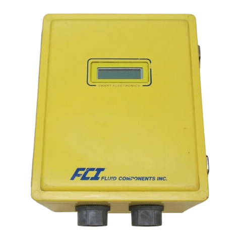
Model ST98
Flowmeter
FirmwareRevisions2.XX
Doc. No. 06EN003291 Rev. A
US PATENTS PENDING

FLUID COMPONENTS INTL
Doc.No.06EN003291 Rev. A iii ModelST98FlowMeter
CUSTOMER COMMITMENT PLEDGE
We will work closely with our customers to provide the best products and service
• at a competitive value
• on time
• with unquestioned support
in full compliance with our COMPLETE CUSTOMER COMMITMENT.
COMMITMENT TO QUALITY
In keeping with the overall commitment of management and employees of Fluid Components Intl to Total Quality
Management, the Technical Publications Department expresses its pledge and mission to you, our customer:
“To support the creation and publication of world-class technical material which is technically accurate and
practical, concise and user-friendly, attractive and professional in appearance, and consistent in form, format,
content, and style.”
QUALITY IMPROVEMENT
We appreciate your comments and suggestions which support our effort to constantly improve our product and
services. Please address comments and suggestions to your nearest field representative or in-house technical
support representative. Thank you. FCI Technical Publications Department

FLUID COMPONENTS INTL
ModelST98FlowMeter iv Doc.No.06EN003291 Rev. A
CUSTOMER SERVICE/TECHNICAL SUPPORT
FCI provides full in-house technical support. Additional technical representation is also provided by FCI field
representatives. Before contacting a field or in-house representative, please perform the troubleshooting tech-
niques outlined in this document.
By Mail
Fluid Components Intl
1755 La Costa Meadows Dr.
San Marcos, CA 92069
Attn: Customer Service Department
By Phone
Contact the area FCI regional representative. If a field representative is unable to be contacted or if a
situation is unable to be resolved, contact the FCI Customer Service Department toll free at
1 (800) 854-1993.
By Fax
To describe problems in a graphical or pictorial manner, send a fax including a phone
or fax number to the regional representative. Again, FCI is available by facsimile if all possibilities have
been exhausted with the authorized factory representative. Our fax number is 1 (760) 736-6250; it is
available 7 days a week, 24 hours a day.
By E-Mail
Describe the problem in detail making sure a telephone number and best time to be contacted is stated in
the e-mail.
International Support
For product information or product support outside the contiguous United States, Alaska, or Hawaii,
contact your country’s FCI International Representative or the one nearest to you. See the list on the
following pages.
After Hours Support
For product information visit FCI's Worldwide Web at www.fluidcomponents.com. For product support
call 1 (800) 854-1993 and follow the prerecorded instructions. A person from the Technical Support Staff
will be paged and promptly return the call.
Appendix C contains a detailed explanation of the FCI customer service policy on returns, adjustments, in-field or
factory repair, in- or out-of-warranty.

FLUID COMPONENTS INTL
Doc.No.06EN003291 Rev. A v ModelST98FlowMeter
REVISIONS
REV. DESCRIPTION DATE AUTHOR
-
INITIAL RELEASE 08/05/99 ROY SANDERS
A See Change Bars. Major changes are due to new 2.xx
Software and Revised circuit boards to Rev. A or Later.
03/01/00 ROY SANDERS

FLUID COMPONENTS INTL
ModelST98FlowMeter vi Doc.No.06EN003291 Rev. A
Contents
1. General Information
Description ........................................................................................................................... 1 - 1
Theory of Operation ............................................................................................................. 1 - 1
Insertion Sensing Element ................................................................................................... 1 - 1
In-Line Sensing Element ..................................................................................................... 1 - 2
Transmitter Electronics ....................................................................................................... 1 - 2
Instrument Configuration .................................................................................................... 1 - 2
Technical Specifications ...................................................................................................... 1 - 3
Quick Start Menu (Abbreviated) ......................................................................................... 1 - 4
2. Installation
Receiving/Inspection............................................................................................................ 2 - 1
Packing/Shipping/Returns ................................................................................................... 2 - 1
Factory Calibration Note...................................................................................................... 2 - 1
Pre-Installation Procedure ................................................................................................... 2 - 1
Use Standard ESD Precautions .................................................................................... 2 - 1
Prepare or Verify Flow Element Location.................................................................... 2 - 2
Verify Dimensions ........................................................................................................ 2 - 2
Verify Flow Direction for Flow Element Orientation and Placement ......................... 2 - 2
Verify The Serial Number Of The Flow Element and the Electronics........................ 2 - 2
Install Insertion Flow Element ............................................................................................ 2 - 3
Compression Fitting Mounting .................................................................................... 2 - 3
NPT Pipe Thread Mounting ......................................................................................... 2 - 3
Flanged Ferrule Mounting............................................................................................ 2 - 3
In-Line Mounting ......................................................................................................... 2 - 4
Install Flow Transmitter ...................................................................................................... 2 - 4
Minimum Wire Size ..................................................................................................... 2 - 5
Aluminum Enclosure Installation ................................................................................ 2 - 5
Carbon Steel Enclosure Installation ............................................................................. 2 - 7
Remote Hardware Location .......................................................................................... 2 - 8
Wiring the In-Line Flow Element ................................................................................ 2 - 8
Serial Communication ......................................................................................................... 2 - 9
Remote Enclosure Bracket Installation ............................................................................... 2 - 10
Apply Power ......................................................................................................................... 2 - 10
3. Operation
Introduction.......................................................................................................................... 3 - 1
Start Up ................................................................................................................................ 3 - 1
Using an FC88 Communicator ............................................................................................ 3 - 1
Menu Control and Organization .................................................................................. 3 - 1
Quick Start Menu................................................................................................................. 3 - 3
Detailed Menu Description .................................................................................................. 3 - 4
Using Procomm Software .................................................................................................... 3 -16
4. Maintenance
Maintenance ......................................................................................................................... 4 - 1
Calibration .................................................................................................................... 4 - 1
Electrical Connections .................................................................................................. 4 - 1
Remote Enclosure ......................................................................................................... 4 - 1
Electrical Wiring .......................................................................................................... 4 - 1
Flow Element Connections ........................................................................................... 4 - 1
Flow Element Assembly ............................................................................................... 4 - 1
5. Troubleshooting
Quick Check......................................................................................................................... 5 - 1
General Function Check ...................................................................................................... 5 - 1
Tools Needed - General Function Check - ................................................................... 5 - 1
NAMUR Fault Indicaton .............................................................................................. 5 - 1
Application Verification ...................................................................................................... 5 - 3

FLUID COMPONENTS INTL
Doc.No.06EN003291 Rev. A vii ModelST98FlowMeter
Equipment Needed........................................................................................................ 5 - 3
Check Serial Numbers .................................................................................................. 5 - 3
Check the Instrument Installation ................................................................................ 5 - 3
Check for Moisture ....................................................................................................... 5 - 3
Check Application Design Requirements .................................................................... 5 - 3
Verify Standard Versus Actual Process Conditions..................................................... 5 - 3
Verify the Calibration Parameters ....................................................................................... 5 - 4
Check the Hardware............................................................................................................. 5 - 5
Equipment Required ..................................................................................................... 5 - 5
Troubleshooting the Flow Element .............................................................................. 5 - 5
Check the Flow Element Voltages ............................................................................... 5 - 6
Verification Of The Electronics........................................................................................... 5 - 7
Check the Flow Transmitter Voltages.......................................................................... 5 - 7
Transmitter Circuit Calibration Check ........................................................................ 5 - 7
Instrument Output Check .................................................................................................... 5 - 8
Spares ................................................................................................................................... 5 - 8
Defective Parts ..................................................................................................................... 5 - 9
Customer Service ................................................................................................................. 5 - 9
Appendix A. Drawings
Outline Drawings and Wiring Diagrams ............................................................................ A - 1
Appendix B. Glossary
Abbreviations and Explanation of Terms............................................................................ B - 1
Appendix C. Customer Service
Policy and Procedures .......................................................................................................... C - 1
Figures
Figure 1-1. View of the Sensing Element .............................................................................................1 - 1
Figure 1-2. Cut-Away View of the In-Line Flow Element Tube ..........................................................1 - 2
Figure 2-1. Model ST98 Insertion Flow Element Showing Orientation ..............................................2 - 2
Figure 2-2. Model ST98 In-Line Butt Weld Mount..............................................................................2 - 4
Figure 2-3. Circuit Board Placement.....................................................................................................2 - 6
Figure 2-4. Customer Connection Board...............................................................................................2 - 6
Figure 2-5. Remote Wiring Diagram ....................................................................................................2 - 7
Figure 2-6. Optional Carbon Steel Enclosure .......................................................................................2 - 8
Figure 2-7. Wiring Diagram, DB-9 and DB-25 PC Connectors. .........................................................2 - 9
Figure 2-8. Remote Bracket Installation ...............................................................................................2 - 10
Figure 3-1. Menu Selections Chart........................................................................................................3 - 2
Figure 5-1. Component Identification ...................................................................................................5 - 5
Figure 5-2. TS2 Connector Plug............................................................................................................5 - 5
Figure 5-3. Terminal Block In Local Enclosure ...................................................................................5 - 5
Figure 5-4. Decade Box Connections ....................................................................................................5 - 8
Figure A-1. Local Enclosure, NEMA Type 4X and Hazardous Location ............................................A - 1
Figure A-2. Remote Aluminum Double Ended Enclosure NEMA 4X and Hazardous Location ........A - 1
Figure A-3. Remote or Local Enclosure, Carbon Steel NEMA Type 4X, and Div 2...........................A - 2
Figure A-4. 3/4 Inch Ferrule NPT Process Connection ........................................................................A - 3
Figure A-5. 3/4 Inch Ferrule NPT With Flange Process Connection...................................................A - 3

FLUID COMPONENTS INTL
ModelST98FlowMeter viii Doc.No.06EN003291 Rev. A
Figure A-6. In-Line Flanged Process Connection.................................................................................A - 3
Figure A-7. In-Line NPT Process Connection ......................................................................................A - 4
Figure A-8. Integral Option Wiring Diagram.......................................................................................A - 4
Figure A-9. Remote Wiring Diagram....................................................................................................A - 4
Figure A-10. Wiring Diagram Between Circuit Boards ........................................................................A - 5
Figure A-11. Optional Display Ribbon Cable Conneciton ...................................................................A - 5
Figure A-12. Remote Mounting Bracket ...............................................................................................A - 5
Tables
Table 1-1. Quick Start Menu .................................................................................................................1 - 4
Table 2-1. Maximum AWG Number ....................................................................................................2 - 5
Table 3-1. Quick Start Menu .................................................................................................................3 - 3
Table 5-1. NAMUR Fault Listing .........................................................................................................5 - 2
Table 5-2. Diagnostic Test Sequence on Display..................................................................................5 - 4
Table 5-3. Flow Element Resistance at TS2 or Local Terminal Block ................................................5 - 6
Table 5-4. Resistance Versus Wire Size................................................................................................5 - 6
Table 5-5. Approximate Flow Element Voltages at 70°F .....................................................................5 - 6
Table 5-6. Instrument Voltages .............................................................................................................5 - 7

FLUID COMPONENTS INTL
Doc.No.06EN003291 Rev. A ix ModelST98FlowMeter
Symbols
The following symbols are used throughout the manual to draw attention to items or procedures that require
special notice or care.
Caution:
Warns of possible personal danger to those handling the equipment.
Alert:
May cause possible equipment damage.
Note:
Contains important information.

CHAPTER 1 - GENERAL INFORMATION FLUID COMPONENTS, INTL
Doc. No. 06EN003291 Rev. A
1 - 1
Model ST98 Flow Meter
1. General Information
Description
The model ST98 is a thermal mass flowmeter for air or gas measuring applications. The ST98 consists of a flow
element, a flow transmitter, and an enclosure. An in-line flow element is used for smaller diameter pipe or tubing
sizes and, for pipe sizes greater than 2-1/2 inches (40 mm bore), an insertion flow element is used. The flow
element’s process connections can be threaded or flanged.
The ST98 flow transmitter accepts AC or DC input power and the output signal can be set for either a standard
range current or voltage. A display is optional. An RS-232C serial I/O port provides setup, monitoring and
troubleshooting access using either FCI’s model FC88 Programmer or a PC-compatible computer.
The ST98 enclosures provide environmental protection for the flow transmitter. The flow transmitter can be
integrally mounted with the flow element or remotely separated from it. Hazardous location local and remote
enclosures are optional.
Theory of Operation
The flow element of the model ST98 uses the thermal dispersion operating principle: A low-powered heater
produces a temperature differential between two resistance temperature detectors (RTDs) by heating one of the
RTDs. Mass flow rate changes cool the heated RTD and cause a proportional change in the temperature
differential between the RTDs. The instrument’s flow transmitter converts the RTD temperature differential into a
scaled output signal and an optional indicated display value.
The signal from the unheated RTD is used to provide an indication of the air or gas temperature on the optional
display.
Insertion Sensing Element
The sensing element consists of two thermowells (hollow tubes) that when inserted into the flow process allows an
unimpeded flow inside the process line. A heated RTD is inserted into the top thermowell. A reference RTD
(with no heater) is inserted into the bottom thermowell. In order to correctly orient the sensing element a flow
arrow has been etched onto a machined flat portion of the sensing element. See Figure 1-1 for a view of the
sensing element.
The element is inserted into the process media through a hole drilled into the process line.
Figure 1-1 View of the Sensing Element
ARROW PARALLEL TO FLOW
ACTIVE RTD (HEATED)
REFERENCE RTD (NOT HEATED)

FLUID COMPONENTS, INTL CHAPTER 1 - GENERAL INFORMATION
Model ST98 Flow Meter
1 - 2
Doc. No. 06EN003291 Rev. A
Figure 1-2. Cut-Away View Of The In-Line Flow Element Tube
ACTIVE (HEATED) RTD
REFERENCE (NOT HEATED) RTD
Transmitter Electronics
The transmitter electronics convert the sensing element's RTD temperature differential into a flow signal that is
read on a display . The transmitter also produces an analog output flow signal suitable to interface with process
controls. The output is a representation of the amount of flow or temperature present in the process. The flow
output is transmitted on a source milliamp output and / or voltage output. Both the flow output and process
temperature can be displayed on an optional LCD display.
There are 2 kinds of enclosures available for the electronics:
1. Standard:
Polyester Coated Carbon Steel Rated NEMA/CSA Type 4X (equivalent to IP66) and Division 2 (Ex n), Rating
is pending. (This is a 6 X 6 X 4 Inch Square Enclosure.) (152.4 X 152.4 X 101.6 mm)
2. Optional:
Aluminum rated for Hazardous Location use Class I and II, Division 1 and 2, Group B, C, D, E, F, G
(previously referred to as NEMA 7 and EEx d IIc) resists the effects of weather and corrosion.
(This is a 4.8 X 9.31 Inch Cylindrical Enclosure.) (121.8 X 236.47 mm)
Instrument Configuration
The instrument can be in integral arrangement (the electronics and the sensing element are combined in one
enclosure), or the instrument can be in a remote arrangement (the electronics and sensing element are in separate
enclosures).
In the case of a remote enclosure, the standard configuration of the sensing element (local) enclosure is an
aluminum rated for Hazardous Location use Class I and II, Division 1 and 2, Group B, C, D, E, F, G (previously
referred to as NEMA7) and EEx d IIC and resists the effect of weather and corrosion. The dimensions are 4.68 X
4.82 inches (119 X 122 mm) and is cylindrical in nature.
In-Line Sensing Element (Flow Tee)
The in-line sensing element is made in the same way as the insertion type of flow element is. To correctly orient
the in-line sensing element, a flow arrow has been etched onto one side of the sensing element.
The in-line flow element is inserted in the process line with the flow arrow pointing in the same direction of flow.
See Figure 1-2 for a cutaway view of the in-line element.

CHAPTER 1 - GENERAL INFORMATION FLUID COMPONENTS, INTL
Doc. No. 06EN003291 Rev. A
1 - 3
Model ST98 Flow Meter
Technical Specifications
• Process Connection
Insertion Configuration:
Soft Seal or Metal Ferrule (Can be Stainless Steel or
Hastelloy C):
3/4 inch male NPT or Flanged
Inline Configuration:
1.0 inch tubing, 1.0, 1.5 or 2.0 inch SCH 40 pipe,
Female NPT, Male NPT, Butt Weld or Flanged.
•Insertion U-Length
Beginning as low as 1.0 inch (25.4 mm) to 21
inches (533 mm).
•Sensing Element Material
All wetted surfaces are 316 Stainless Steel, with all-
welded construction. Hastelloy C-276 is optionally
available.
•Operating Temperature
Control circuit:
Ambient temperature configuration:
0 to 140°F (-18 to 60°C).
Sensing element:
Standard temperature configuration:
-40 to 350°F (-40 to 177°C).
•Operating Pressure
0 to 250 psig [0 to 17 bar(g)]. (Derated with
Teflon ferrule.)
•Flow Range
Insertion:
0.75 to 600 SFPS (0.006 to 0.23 NMPS)
Inline:
0.0062 to 1850 SCFM (0.01 to 3140 Nm
3
/h)
•Signal Output
4-20 mA, 700 ohms maximum load
0-5, 1-5 and 0-10 Volts DC 100K ohms minimum
load
•Accuracy
Flow accuracy:
±1 % reading + 0.5% full scale
Temperature accuracy:
±2°F (display only, flow rate must be greater
than 1 SFPS).
•Repeatability
±0.5% of reading.
•Input Power
A.C. Input: 100-240 VAC 50/60 Hz. 17 Watts
Maximum 120 mA Maximum.
D.C. Input: 22-30 VDC 250 mA Maximum 7.5 Watts
Maximum.
• Pending Approvals
FM, CSA, CENELEC, CE Marking
(EMC Directive 89/336/EEC)

FLUID COMPONENTS, INTL CHAPTER 1 - GENERAL INFORMATION
Model ST98 Flow Meter
1 - 4
Doc. No. 06EN003291 Rev. A
Quick Start Menu (Abbreviated)
The following menu shows how to use the most frequently accessed functions of the instrument. For a complete
menu and explanation see Chapter 3 - Operation.
Table 1-1. Quick Start Menu (Abbreviated Menu, See Chapter 3 For Full Details)
PRESS [ENTER] AFTER
EACH MENU SELECTION
TO ACTIVATE COMMAND
K-FACTOR
SOFTWARE
RESET
RE-CONFIGURE
FC88
NORMAL
OPERATING
MODE
TOTALIZE
MODE
NAMUR
FAULT
INDICATOR
FLOW
UNITS
SELECT
DISPLAY
OF TOTAL
FLOW TIME
OUTPUT
MODE
SELECT
EXITS COMMAND
K.F. = 1.0000000
CHANGE IT?<
NO
YES
REINITIALIZES
WITHOUT
POWER DOWN
EXITS COMMAND
RESETS FC88
TO USE WITH
ST98
EXITS COMMAND
RESET IT?<
TIME = 0.0000000 EXITS COMMAND
NO
YES
OUTPUT: XXX
CHANGE IT?<
0: 4-20
1: 0-5
2:0-10
ENTER#
EXITS COMMAND
NO
YES
ON/OFF
TOGGLE
NO
YES
INPUT K.F.#
RESET TOTALIZER
YES
NO
RESET AT POWER UP
NO
YES
TEMP DISPLAY
ON/OFF TOGGLE
YES
EXITS COMMAND
NO
INPUT
PASSCODE
NAMUR FLAG IS
OFF, TURN ON
OR
ON, TURN OFF
EXITS COMMAND
ENGLISH
OR
METRIC
F SFPS(VELOCITY)
C SCFM(VOLUME)
L LBS/HR (MASS)
E
M
F
C
L
SEE THE LAST
PAGES OF
CHAPTER 3
- OPERATION -
FOR DETAILS
M SMPS(VELOCITY)
N NCMH(VOLUME)
K KG/HR (MASS)
M
N
K
SEE THE LAST
PAGES OF
CHAPTER 3
- OPERATION -
FOR DETAILS
ST98 ABBREVIATED MENU
[N]
[F]
[X]
[P]
[T]
[U]
[V]
[W]
[Z]
IOUT:22mA
CHANGE IT?
IOUT: 3.5mA
CHANGE IT?
NO
0=22.0mA
1=3.5mA
YES

Doc. No. 06EN003291 Rev. A 2 - 1
Model ST98 Flow Meter
CHAPTER 2 - INSTALLATION FLUID COMPONENTS, INTL
2. Installation
Receiving/Inspection
•Unpack carefully.
•Verify that all items in the packing list are received and are correct.
•Inspect all instruments for damage or contaminants prior to installation.
If the above three items are satisfactory, proceed with the installation. If not, then stop and contact a customer
service representative.
Packing/Shipping/Returns
These issues are addressed in Appendix C - Customer Service.
Factory Calibration Note
The instrument is factory calibrated to the flow range specified in the order. There is no need to perform any
verification or calibration steps prior to installing and placing the instrument in service.
Pre-Installation Procedure
Caution: Only qualified personnel should install this instrument. Install and follow safety procedures in
accordance with the current National Electrical Code. Ensure that power is off during installation.
Any instances where power is applied to the instrument will be noted in this manual. Where the
instructions call for the use of electrical current, the operator assumes all responsibility for
conformance to safety standards and practices.
Alert: The instrument is not designed for weld-in-place applications. Never weld to process connection or a
structural support.
Damage resulting from moisture penetration of the enclosure(s) is not covered by product warranty.
The flow transmitter contains electrostatic discharge (ESD) sensitive devices. Use standard ESD
precautions when handling the circuit board assemblies. See below for ESD details.
Use Standard ESD Precautions
Use standard ESD precautions when opening an instrument enclosure or handling the flow transmitter. FCI
recommends the use of the following precautions: Use a wrist band or heel strap with a 1 megohm resistor
connected to ground. If the instrument is in a shop setting there should be static conductive mats on the work table
and floor with a 1 megohm resistor connected to ground. Connect the instrument to ground. Apply antistatic
agents to hand tools to be used on the instrument. Keep high static producing items away from the instrument
such as non-ESD approved plastic, tape and packing foam.
The above precautions are minimum requirements to be used. The complete use of ESD precautions can be found
in the U.S. Department of Defense Handbook 263.

FLUID COMPONENTS, INTL CHAPTER 2 - INSTALLATION
Model ST98 Flow Meter 2 - 2 Doc. No. 06EN003291 Rev. A
Prepare or Verify Flow Element Location
Prepare the process pipe for installation or inspect the already prepared location to ensure that the instrument will
fit into the system.
Mount the flow element at least 20 diameters downstream and 10 diameters upstream from any bends or
interference in the process pipe or duct to achieve the greatest accuracy.
Verify Dimensions
The ST98 Insertion Models have an adjustable insertion length ferrule until it is locked into position. Verify all
dimensions before locking the fitting in place. See the appropriate figures in Appendix A.
Note: Two types of ferrules are available. One type of ferrule is made from Teflon. This can be tightened and
loosened repeatedly at different places on the flow element. The other type of ferrule is made from
Stainless Steel. This ferrule can only be tightened in one place on the flow element. The Stainless Steel
Ferrule makes an indentation into the flow element for a more firm fit.
The ST98 In-Line Model's flow element has a tube or pipe length and diameter that is specified at the time of
order. This dimension should be double checked with the process line.
Verify Flow Direction for Flow Element Orientation and Placement
The insertion ST98 flow element comes with flat areas machined on the flow element near the enclosure end of the
flow element. Etched on the flow element is a flow arrow indicating the direction of flow. See Figure 2-1.
Align the ST98 flow element during installation so the flat areas are parallel to the direction of the process media
flow, and the flow arrow points in the direction of process media flow.
A flow direction arrow is etched on the in-line ST98 tube or pipe and should be pointing in the direction of flow.
Failing to install the flow element correctly will reduce the accuracy of the flow meter.
Verify The Serial Number Of The Flow Element and the Electronics
The ST98 flow element has a serial number near the flat machined area or flow arrow. The same number is on the
main electronics circuit board, and on the tag of the electronics enclosure. These numbers have to match because
the flow element and the electronics are a matched set. Failure to observe serial numbers will cause inaccurate
readings.
Figure 2-1. Model ST98 Insertion Flow Element (Remote) Showing Orientation

Doc. No. 06EN003291 Rev. A 2 - 3
Model ST98 Flow Meter
CHAPTER 2 - INSTALLATION FLUID COMPONENTS, INTL
Install Insertion Flow Element
Note
:The instrument accuracy will be reduced if the media flow is reversed from the flow direction of the flow
arrow machined on the flow element or if the flats are not parallel, within ±1° of the flow direction.
Install the flow element as specified for the process connection type used.
Compression Fitting Mounting (Insertion Mounting Only)
1. Determine the inside diameter of the process pipe at the predetermined location. Calculate 1/2 of the inside
diameter. Add 0.50 inch (12.7 mm) to the dimension. Add the pipe wall thickness. Mark the flow element at
this length.
2. Insert the flow element fitting into the process pipe and tighten per ANSI B16.5 torque specifications. Use
appropriate sealants as required. Measure the length of the ferrule that is above the pipe. Mark this
dimension above the first mark on the flow element.
3. Position the flow element in the process pipe so that the last mark is above the ferrule. The flow element is
now placed at 0.50 inch (12.7 mm) past the center of the process pipe as shown in Figure 2-1.
4. Adjust the flow element so the flats are parallel to flow ±1°, and the flow arrow is in the direction of flow.
5. Ensure that the insertion length is correct before tightening the compression fitting. Readjustment of the
metal ferrule is not possible after tightening because the fitting crimps onto the flow element pipe. The Teflon
ferrule is readjustable.
6. Hold the fitting body steady with a backup wrench and tighten the nut one and one-quarter turns past what is
hand tight. Now the flow element is sealed and locked into place.
Caution:
Be sure there is no pressure in the process line before the instrument is removed.
To remove the flow element, loosen the nut (Step 6) and unscrew the ferrule (Step 2).
NPT Pipe Thread Mounting (Insertion Mounting Only)
Alert:
DO NOT change the orientation of the flow element in the enclosure more than 180° as the
interconnecting RTD and heater wiring could be stressed and damaged. DO NOT apply any torque
to the flow element enclosure - only apply to NPT pipe surface itself.
Note:
When mounting the flow element to the process pipe, it is important that a lubricant/sealant is applied to
the male threads of all connections. A lubricant/sealant compatible with the process environment should
be used. All connections should be tightened firmly. To avoid leaks do not overtighten or cross-thread
connections.
The pipe thread configuration is similar to what is shown in Figure 2-1. Apply sealant compatible with the process
media to male threads. Carefully insert into process mount. Threads are right-handed. Tighten with an open-end
wrench on the hexagonal surface provided. Rotate until snug and continue to turn until flat is horizontal to
process flow.
Flanged Ferrule Mounting (Insertion Mounting Only)
1. One of the configurations that can be ordered is a flange that has NPT threads. The flange can be screwed onto
the instrument's ferrule. If the flange is sperate from the ferrule screw on the flange and apply a lubricant/
sealant to the male threads and torque using ANSI B16.5 specifications. If the flange is already present,
proceed to the next step.
2. Measure the U-Length of the flow element (from the flange face to the end of the flow element). Subtract
0.50 inch (12.7 mm) from the U-Length. The process' flanged mating surface for the flow element should be
high enough above the pipe for proper mounting of the flow element as follows: Measure the inside diameter

FLUID COMPONENTS, INTL CHAPTER 2 - INSTALLATION
Model ST98 Flow Meter 2 - 4 Doc. No. 06EN003291 Rev. A
of the process pipe at the predetermined location. Calculate 1/2 of the inner diameter. Add the pipe wall
thickness. Add the length the customers flange is above the pipe. The length above the pipe should be
adjusted to match the U-Length minus the 0.50 inch (12.7 mm) dimension.
3. Apply the appropriate gasket and/or sealant to flange mount faces as required.
4. Attach the process mating flange with care. The mating surface should be oriented so the flow element flats
are parallel to flow, within ±1°, and the flow arrow on the flow element should be pointing in the same
direction as the flow.
5. Attach with a bolt, two flat washers, lock washer and nut for each bolt hole; apply lubricant/sealant to the
male threads and torque. Refer to ANSI B16.5 specifications.
In-Line Mounting
There are several different ways the in-line model ST98 instrument can be mounted into the process line. The
different ways the flow element can be mounted are as follows:
•
Threaded male NPT mount
•
Threaded female NPT mount
•
Raised face flange mount
•
Butt Weld mount
Figure 2-2 shows a Butt Weld, 2 inch Schedule 40 pipe, in-line model ST98:
Mount the in-line Model ST98 as follows:
1. Verify that the process media flow is in the same direction as the flow arrow (see Figure 2-2).
2. For flange mounted instruments, apply the appropriate gasket and / or sealant to flange mounts as
required.
3. For NPT mounted instruments, apply the appropriate sealant to the threads as required.
4. Mate (or weld the Butt Weld instrument) the instrument to the process line.
5. For flange mounts, attach the instrument with a bolt, two flat washers, lock washer and a nut for each bolt
hole. Apply lubricant/sealant to the male threads of bolts or to the NPT threads and torque. Refer to
ANSI B16.5 torque specifications.
Install Flow Transmitter
Alert:
In applications where the flow element is located in an explosive environment, isolate the conduit
before it leaves the environment. A potting Y may be used to provide the isolation.
Note:
FCI recommends installing an input power disconnect switch and fuse near the flow transmitter to
interrupt power during installation, maintenance, calibration, and troubleshooting procedures.
Figure 2-2. Model ST98 In-Line Butt Weld Mount

Doc. No. 06EN003291 Rev. A 2 - 5
Model ST98 Flow Meter
CHAPTER 2 - INSTALLATION FLUID COMPONENTS, INTL
Make all electrical connections through the 3/4 inch NPT ports in the enclosure. Run all electrical cables through
appropriate conduit or protective sheathing.
Caution:
Ensure that all power is off before wiring any circuit.
Minimum Wire Size
If the instrument is used in the remote configuration, a shielded, 8 conductor cable should be used between the
local and remote enclosure. Table 2-1 shows the smallest (maximum AWG number) copper wire that should be
used in the cable and in other wiring. Use a lower gauge of wire for less of a voltage drop. Contact FCI
concerning greater distances than those listed in the table. The sensing element cable for the remote option must
be shielded. The maximum wire size of the non-power connectors in the instrument is 16 AWG. The maximum
wire size of the power connectors in the instrument is 12 AWG.
Note:
All 8 conductors for the sensing element must be used for proper operation of the flow meter.
Table 2-1. Maximum AWG Number
Aluminum Enclosure Installation (Cylindrical Enclosure)
1. To wire the instrument remove the customer connection cover from the instrument by loosening the Allen
head screw at the base of the cover. Unscrew the cover shown in Figure 2-3.
2. Install conduit between the local (if used) and the remote enclosure, the power source and customer
monitoring circuits. Provide watertight hardware and apply thread sealant to all connections to prevent water
damage.
3. Connect the milliamp and/or DC voltage output to the termination (customer connection) board as required.
Refer to Figure 2-4 for connection information.
4. Connect the operating power to the customer termination board by removing the input wiring kit from the
strain relief bracket (see Figure 2-4 for the bracket location). This kit contains a filter bead and three cable
ties. For remote instruments only, the kit also contains 2 wire terminals for a ground wire to be placed
between the flow element enclosure and the electronics enclosure.
5. Strip the incoming power wires to approximately 5/16 of an inch.
6. Attach the filter bead over the safety ground wire as shown in Figure 2-4 using 2 cable ties to secure the bead
on the wire. The last cable tie should be about 3 inches from the end of the wire.
7. Attach the power wires to Terminal Strip TS1 (for AC) or TS4 (for DC) as shown in Figure 2-4. Secure the
wires going to the Terminal Strip with a cable tie, secured to the cable tie bracket on the customer connection
board.
8. For remote instruments only, (the flow element is in a separate enclosure from the electronics):
Loosen the Allen head screw on the electronics cover. Unscrew the cover.
Maximum Distance for AWG
Connection
Input Power
Sensing Element Cable
(Remote Instrument)
Analog Output
10 ft.
(3 m)
50 ft.
(15 m)
100 ft.
(31 m)
250 ft.
(76 m)
500 ft.
(152 m)
1000 ft.
(310 m)
24
24
1820 18
18 16
1824
24
24
24 16
16
16
16 16 14

FLUID COMPONENTS, INTL CHAPTER 2 - INSTALLATION
Model ST98 Flow Meter 2 - 6 Doc. No. 06EN003291 Rev. A
Figure 2-3. Circuit Board Placement
9. For remote instruments only: The flow element wires should be routed through the 3/4 inch NPT port for the
flow element as shown in Figure 2-3. Connect the flow element wires to TS2 on the electronics assembly
according to Figure 2-5. Connect the cable shield to HTR RTN. Leave the other end of the shield floating.
A 14 AWG ground wire should also be routed between the enclosures (wire terminals are supplied in the kit).
Note:
Connecting the shield in any other way will decrease the accuracy of the instrument. See Figure 2-4
for the wiring diagram.
Caution:
Be sure an earth ground wire is connected to the ground terminal (see Figure 2-4). On a remote
configuration, connect an earth ground wire to the ground screw in the local enclosure. This is for
the purpose of safety.
10. If a wire comes loose from the instrument during installation, refer to Chapter 5 - Troubleshooting for a
complete instrument wiring diagram.
Figure 2-4. Customer Connection Board
POWER
AND
SIGNAL
CONNECTION
BOARD
3/4 INCH NPT PORT (2 PLACES)
OPTIONAL
DISPLAY
GLASS
3/4 INCH NPT
PORT FOR
FLOW ELEMENT
ELECTRONICS
ELECTRONICS COVER
(NO USER ACCESS
NECESSARY FOR
INTEGRAL INSTRUMENTS)
CUSTOMER
CONNECTION
COVER
OPTIONAL DISPLAY
P1
TS1
TS4 TS3
TIE DOWN
BRACKET
CABLE TIES
FERRITE BEAD

Doc. No. 06EN003291 Rev. A 2 - 7
Model ST98 Flow Meter
CHAPTER 2 - INSTALLATION FLUID COMPONENTS, INTL
Caution:
Ensure that all power is off before wiring any circuit.
Carbon Steel Enclosure Installation (6 X 6 Carbon Steel Enclosure)
1. To wire the instrument loosen 3 cover hold down screws and open the cover. See Figure 2-6.
2. Install conduit between the local (if used) and the remote enclosure, the power source and customer monitoring
circuits. Provide watertight hardware and apply thread sealant to all connections to prevent water damage
.
3. Connect the milliamp and/or DC voltage output to the termination (customer connection) board as required.
Refer to Figure 2-4 for connection information.
4. Connect the operating power to the customer termination board by removing the input wiring kit from the
strain relief bracket (see Figure 2-4 for the bracket location). This kit contains a filter bead and three cable
ties. For remote instruments only, the kit also contains 2 wire terminals for a ground wire to be placed
between the flow element enclosure and the electronics enclosure.
5. Strip the incoming power wires to approximately 5/16 of an inch.
6. Attach the filter bead over the safety ground wire as shown in Figure 2-4 using 2 cable ties to secure the bead
on the wire. The last cable tie should be about 3 inches from the end of the wire.
11. For remote instruments only: Screw on the electronics cover and tighten the Allen head screw.
12. Screw on the customer connection cover and tighten the Allen head screw.
13. There are enough threads on the flow element so the flow transmitter enclosure can be rotated for ease of
viewing the display LCD if the option is present. Be sure the flow arrow still points in the direction of flow
and the flat is parallel to the flow.
14. Verify proper installation. Ensure that the assemblies are secure and the wiring is correct.
Figure 2-5. Remote Wiring Diagram
RTD GND 1
GND SEN 2
REF SEN 3
ACT SEN 4
REF EXC 5
ACT EXC 6
HTR EXC 7
HTR RTN 8
BOARD ASSY.
P/N 017749
TS2
1
2
3
4
5
6
7
8
LOCAL
ENCLOSURE
TB1
SENSOR
ELEMENT
USE 8 CONDUCTOR SHIELDED CABLE ONLY
RTD GND 1
GND SEN 2
REF SEN 3
ACT SEN 4
REF EXC 5
ACT EXC 6
HTR EXC 7
HTR RTN 8
SHIELD
14 AWG GROUND SAFETY WIRE
P5
P4
TS2 SOCKET
ENCLOSURE
P3
TP1
EPROM
TS2
PLUG

FLUID COMPONENTS, INTL CHAPTER 2 - INSTALLATION
Model ST98 Flow Meter 2 - 8 Doc. No. 06EN003291 Rev. A
Remote Hardware Location (Option)
The outline dimensions shown in Appendix A show the physical dimensions for the proper mounting of the flow
element and transmitter electronics enclosure. Select a location for the flow transmitter within 1000 feet (310 M)
of the flow element. Pigtail flow elements can not be located more than 10 feet (3 M) from the flow transmitter.
This location should be easily accessible with enough room to unscrew the enclosure top at any time. Secure the
enclosure to a surface capable of providing support. Use appropriate hardware to secure the enclosure.
Note:
In cases where a pigtail flow element cable must be extended, a 9 position terminal strip must be used.
All 8 conductors and the shield wire must have an exclusive terminal landing for proper operation. See
Table 2-1 for the minimum wire gauge to use.
Wiring the In-Line Flow Element (Option)
Electrically the in-line flow element is the same as the model ST98 insertion flow element. Wire the instrument
using the local enclosure or remote enclosure and/or the pigtail wiring methods above.
Figure 2-6. Optional Carbon Steel Enclosure
POWER
AND
SIGNAL
CONNECTION
BOARD
ELECTRONICS
3/4 INCH NPT
PORT FOR INTEGRAL
FLOW ELEMENT 3/4 INCH NPT PORT
FOR REMOTE
FLOW ELEMENT
3/4 INCH NPT PORT
POWER INPUT
OPTIONAL
DISPLAY
HOLD DOWN SCREWS
(3 PLACES)
3/4 INCH NPT PORT
SIGNAL OUTPUT
7. Attach the power wires to Terminal Strip TS1(for AC) or TS4 (for DC) as shown in Figure 2-4. Secure the
wires going to the Terminal Strip with a cable tie, secured to the cable tie bracket on the customer connection
board.
8. For remote instruments only, (the flow element is in a separate enclosure from the electronics):
The flow element wires should be routed through the 3/4 inch NPT port for the flow element as shown in
Figure 2-6. Connect the flow element wiresto TS2 on the electronics assembly according to Figure 2-5.
Connect the cable shield to HTR RTN. Leave the other end of the shield floating.
Note:
Connecting the shield in any other way will decrease the accuracy of the instrument. See Figure 2-5
for the wiring diagram.
Caution:
Be sure a grounded wire is connected to the ground terminal (see Figure 2-4) or to the enclosure
ground screw. This is for the purpose of safety.
9. If a wire comes loose from the instrument during installation, refer to Chapter 5 - Troubleshooting for a
complete instrument wiring diagram.
10. Close the cover and tighten the hold down screws.
11. There are enough threads on the flow element so the flow transmitter enclosure can be rotated for ease of
viewing the display LCD if the option is present. Be sure the flow arrow still points in the direction of flow
and the flat is parallel to the flow.
12. Verify proper installation. Ensure that the assemblies are secure and the wiring is correct.
Table of contents
Other Fluid Components Intl Measuring Instrument manuals
