Greyline TTFM 6.1 User manual

www.greyline.com
USER'S GUIDE
Installation & Operation
Instructions
Transit Time Flow Meter
Model TTFM 6.1
Manual Series A.1.6

Note: This page has been left blank intentionally.

Page 3
TTFM 6.1 Transit Time Flow Meter
INDEX
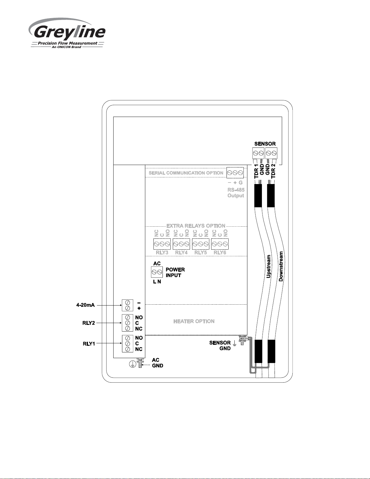
CONNECTIONS ......................................................................................................................................4
KEYPAD SYSTEM..................................................................................................................................6
MENU SYSTEM......................................................................................................................................7
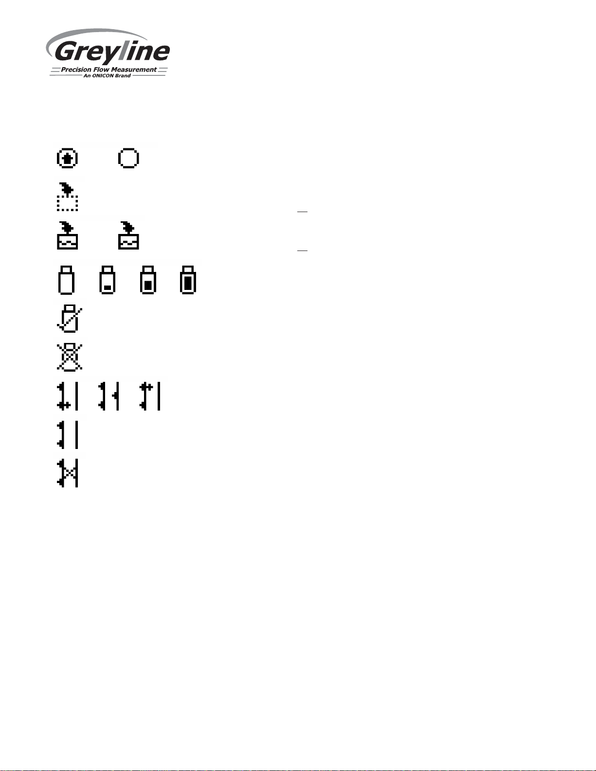
ICONS ......................................................................................................................................................8
MESSAGE ICON .....................................................................................................................................9
STATUS ...................................................................................................................................................9
PASSWORD...........................................................................................................................................11
MENU SELECTIONS............................................................................................................................ 11
UNITS/MODE........................................................................................................................................ 12
SET UP ................................................................................................................................................... 14
CALIBRATION .....................................................................................................................................17
RELAY PARAMETERS........................................................................................................................ 19
DATA LOGGING ..................................................................................................................................20
COMMUNICATION (OPTIONAL) ......................................................................................................22
SPECIAL FUNCTIONS......................................................................................................................... 24
TYPICAL SENSOR INSTALLATION.................................................................................................. 27
SENSOR MOUNTING........................................................................................................................... 30
2 OR 4 CROSS INSTALLATION OVERVIEW - TMK-B1 KIT.......................................................... 31
1 CROSS INSTALLATION OVERVIEW – TMK-B1 KIT................................................................... 35
2 OR 4 CROSS INSTALLATION OVERVIEW - TMK-B21 OR TMK-B22 KIT................................42
1 CROSS INSTALLATION OVERVIEW – TMK-B21 OR TMK-B22 KIT ........................................46
SENSOR MOUNTING/COUPLING RECOMMENDATIONS ............................................................ 53
ENCLOSURE INSTALLATION ........................................................................................................... 54
FIELD TROUBLESHOOTING..............................................................................................................55
COMMON QUESTIONS AND ANSWERS..........................................................................................58
APPLICATIONS HOTLINE.................................................................................................................. 60
PRODUCT RETURN PROCEDURE ....................................................................................................60
SPECIFICATIONS................................................................................................................................. 64
APPENDIX A - CONVERSION TABLE ..............................................................................................65
PIPE CHARTS........................................................................................................................................66
APPENDIX C – LIQUID SPEED OF SOUND...................................................................................... 71
APPENDIX D......................................................................................................................................... 78
IMPORTANT NOTE: This instrument is manufactured and calibrated to meet product specifications. Please read this
manual carefully before installation and operation. Any unauthorized repairs or modifications may result in a suspension of
the warranty. If this product is not used as specified by the manufacturer, protection may be impaired.
Available in Adobe Acrobat pdf format

Page 4
TTFM 6.1 Transit Time Flow Meter
CONNECTIONS:
POWER INPUT: The standard model requires AC power input between 100 to 240 VAC 50/60Hz
10VA. No adjustments are necessary for voltages within this range. Connect L (Live) N (Neutral) and
AC Ground.
Optional DC input model requires 9-32 VDC/10 Watts. Connect to + and - terminals.
Optional Thermostat and Heater modules are available rated for specifically 115 VAC or specifically
230 VAC.
IMPORTANT NOTE: To comply with electrical safety standards, AC power input and relay connection
wires must have conduit entry to the instrument enclosure. Installation requires a switch, overcurrent
fuse or circuit breaker in the building (in close proximity to the equipment) that is marked as the
disconnect switch.
Risk of electric shock. Loosen cover screw to access connections. Only qualified personnel
should access connections.
Note: Use of instrumentation over 40°C ambient requires special field wiring.
Note: Some models feature a user replaceable fuse. Fuse is 2 Amp 250V (T2AL250V), located on the
power supply.

Page 5
TTFM 6.1 Transit Time Flow Meter
100-240 VAC Meter CONNECTIONS

Page 6
TTFM 6.1 Transit Time Flow Meter
KEYPAD SYSTEM
The diagram on page 7 shows the TTFM 6.1 menu system. Arrows show the four directions to leave a
menu box. Pressing a corresponding keypad arrow will move to the next item in the direction shown.
Move the cursor (highlighted) under numerals and increase or decrease numerals with the and
keys.
To store calibration values permanently (even through power interruptions), press the button.

Page 7
TTFM 6.1 Transit Time Flow Meter
MENU SYSTEM
--Messages----------
LData og Logging
dLog Use 0.00000%
Sensor Good
--24 hr log----------
Date Feb. 12/20
10
Total 50138 USG
34.82 USG/mAverage
52.20 USG/mMaximum
11:08:00Max Time
0.000 USG/mMinimum
9:15:00Min Time
--Menu--------------
Units / Mode
Setup
Calibration
Relay Parameters
Data Logging
Communication
Special Functions
Simulation
Configuration
USG/m
Tot 20130 USG
Relays 1 2 3 4 5 6
0.00
*
* Menu only appears if "New Password" has been
changed from 0000 in "Special Functions" menu.
--Password----------
Password 0000
--Status------------
Velocity ft/s
0.00
Flow 0.00 USG/m
Min Flow 4.00 USG/m
Signal Strength 100%
Exp. SOS 4900 ft/s
Meas. SOS 4900 ft/s
--Data Logging-------
Log Site ID 01
Mode Flow
File Format .LG2
Date 6 7Jun 2 /201
Time 12:28:41
Interval 30sec
Data Log Logging
--Relay Parameters--
Relay 1
Function Flow
On 1000 USG
Off 0.000 USG
--Simulation--------
Test Actual
Flow /m250USG
Flow4-20mA 5.60mA
Relays 1 2 3 4 5 6
--Configuration-----
Serial# 12345
Utility 1.25.0.16
1.Transit Time 38.1
CommBoard 1. .21 19
Relays 2
Analog Out 1
--Communication-----
Protocol Modbus
Address 001
BPS 9600
Parity Even
Stop Bits 1
--Special Functions-
Language English
Analog Out 4-20mA
Backlight High
Reset Totalizer NO
Neg. Totals NO
Rev. Flow OFF
Capture Par NO
Capture WF NO
Restore Defaults NO
New Password 0000
-- -------
Setup------
r SE16B
Senso
Angle 37
°
Fluid Water
Temp Mode Fixed
Temp 77.0 F
Pipe PVC
OD 4.5000 in
Wall 0.2500 in
Lining None
Crossings 2
Zero Tare No
Sens Space 2.299in
Velocity 0.00 ft/s
Signal
Strength
100
%
--Calibration-------
Mode Flow
20mA 500.00 USG/m
4mA 0.00 USG/m
LOS Time 10 sec
Min Flow
4.00 USG/m
Damping
Mode FIR
Percent 10%
Window 1.0 ft/s
Cal Constant 1.00
--Units/Mode--------
Mode Flow
Linear in
Volume USG
Multiplier x1
Decimal 0s
Velocity ft/s
Flow USG/m
Decimal 2s
emperature
T F
optional features

Page 8
TTFM 6.1 Transit Time Flow Meter
ICONS
1.
1.
2.
2.
Message waiting. Press .from main page to view
Data logging .off
Data logging .on
1.
1.
2.
2.
3.
3.
4. USB file download .ing
File download completed.
Download Error.
TTFM Echo OK.
TTFM - , Empty Pipe .Low Signal / No Echo or high Aeration
TTFM - No Sensors Attached / Wrong Settings

Page 9
TTFM 6.1 Transit Time Flow Meter
MAIN DISPLAY
The Main Display shows the units selected from the Units/Mode menu, flow rate
or velocity rate being measured, totalizer, totalizer multiplier, and relay states. The
TTFM 6.1 will go to this display after start-up.
MESSAGE ICON
Press from the Main Display to view status of the data logger and
error/warning messages provided by the instrument. The Message Icon will
appear on the Main Display if error messages are being generated by the
instrument. Press to return to the Main Display.
STATUS
Press from the Main Display to view Status of the measurement. Press to
return to the Main Display.
Velocity Displays flow velocity in ft/s or m/s, selected in the
Units/Mode menu.
Flow Displays flow rate in units selected in the Units/Mode
menu. A list of flow rate units is provided in the
Units/Mode section of the manual.
Min Flow Displays a read-only value for the minimum flow cutoff,
in units which match the Flow selection. Measured flow
rates below the Min Flow will result in the displayed
flow rate on the LCD display to be 0.0. This parameter is
used to suppress electrical noise at zero flow conditions,
and it is typically set to the flow rate equivalent of 0.1
ft/sec in the programmed pipe size. The Min Flow can be
adjusted in the Calibration menu.
Signal Strength Displays magnitude of signal being received by the
ultrasonic sensors. 100% is the ideal signal strength.
Signal strengths less than 100% could indicate poor pipe
conditions (corrosion), highly aerated water, or
programmed setup parameters which don’t closely
match field conditions. Consideration should be made to
use 1-cross installation method in such cases, if not
already using it.
USG/m
Tot 20130 USG
Relays 1 2 3 4 5 6
0.00
--Status------------
Velocity ft/s0.00
Flow 0.00 USG/m
Min Flow 4.00 USG/m
Signal Strength 100%
Exp. SOS 4900 ft/s
Meas. SOS 4900 ft/s

Page 10
TTFM 6.1 Transit Time Flow Meter
Status (cont.)
Exp. SOS Displays the expected fluid speed of sound
measurement, in units that match the Velocity. The
expected speed of sound is based on the pipe, fluid, and
temperature selection in the Setup menu.
Meas. SOS Displays the measured fluid speed of sound, in units that
match Exp. SOS. The meter calculates this value based
on the time it takes for the signal to arrive from one
transducer to another. Large differences between
expected and measured speed of sound (> 10%) typically
indicate an error in the setup of the instrument. Verify
the following are correct in the Setup menu and with the
physical installation of the transducers:
- Pipe Material
- Pipe OD
- Pipe Wall Thickness
- Liner Type
- Liner Thickness
- Fluid Type
- Fluid Temperature
- Crossings
- Separation Distance
--Status------------
Velocity ft/s0.00
Flow 0.00 USG/m
Min Flow 4.00 USG/m
Signal Strength 100%
Exp. SOS 4900 ft/s
Meas. SOS 4900 ft/s

Page 11
TTFM 6.1 Transit Time Flow Meter
24 HR LOG
Press from the Main Display to view a formatted flow report. Press to scroll
down one day or repeatedly to scroll to a specific date. Up to 365 days will be
stored. Newest date will overwrite the oldest. Press to return to the Main
Display.
IMPORTANT: Inserting a USB drive into the meter while on this screen will
transfer 24 HR Log data to the USB drive in .csv format.
PASSWORD
The Password (a number from 0000 to 9999) prevents unauthorized access to the
Calibration menu.
From the Main Display press the key to get to Password. Factory default
password is 0000 and if it has not been changed, this screen will be bypassed
completely.
A new password can be stored by going to the Special Functions New
Password menu.
If a user password is required, press to place the cursor under the first digit and
or to set the number, then to the second digit, etc. Press or to proceed
to the Menu Selections screen.
MENU SELECTIONS
The Menu selections page is used to navigate to specific menus which are
described in more detail on the following pages.
Press or to navigate to different menus, and to enter the selected menu.

Page 12
TTFM 6.1 Transit Time Flow Meter
UNITS/MODE
At Mode, press the and then the or to select Flow or Velocity. Flow
mode displays the flow rate in engineering units (e.g. gpm, litres/sec, etc.) Press
the to store your selection then the to the next menu item.
At Linear press the key and then the or to select your units of
measurement. The Linear units define what units the pipe dimensions and sensor
spacing will be displayed in. Typically inches or mm is selected. Press the to
store your selection then the
to the next menu
item
.
At Volume, press the
and then the
or
to select units for volume. Note:
“bbl” denotes US oil barrels. Press the to store your selection then the to the
next menu item.
At Multiplier, press the
and then the
or
to select the totalizer
multiplier. Multipliers are used when resolution down to single digit is not
required, or when you don’t want to convert from gallons to thousands of gallons,
as an example. Press
to store your selection then
to the next menu i
tem.
At Decimals (Volume), press the
and then the
or
to select the number
of decimal points to be present on the totalizer display on the LCD screen. Default
= 0. Options = 0, 1, 2. Press the to store your selection then the to the next
menu item.
At Velocity, press the
and then the
or
to select the engineering
units for flow velocity and sonic velocity of the fluid. Press to store your
selection then
to the next menu item.
--Units/Mode--------
Mode Flow
Linear in
Volume USG
Multiplier x1
Decimal 0s
Velocity ft/s
Flow USG/m
Decimal 2s
emperatureT F

Page 13
TTFM 6.1 Transit Time Flow Meter
UNITS/MODE (cont.)
At Flow, press the and then the or to select the engineering units for
flow rate. Press to store your selection then to the next menu item.
Available Flow Rate Engineering Units:
Abbreviation Description Abbreviation Description
USG/d US gallons per day L/d liters per day
USG/h US gallons per hour L/h liters per hour
USG/m US gallons per minute L/m liters per minute
USG/s US gallons per second L/s liters per second
ft3/d cubic feet per day m3/d cubic meters per day
ft3/h cubic feet per hour m3/h cubic meters per hour
ft3/m cubic feet per minute m3/m cubic meters per minute
ft3/s cubic feet per second m3/s cubic meters per second
bbl/d barrels per day (1 bbl = 42 USG) IG/d Imperial gallons per day
bbl/h barrels per hour (1 bbl = 42 USG) IG/d Imperial gallons per day
bbl/m barrels per minute (1 bbl = 42 USG)
gal)
IG/d Imperial gallons per day
bbl/d barrels per second (1 bbl = 42 USG)
gal)
IG/d Imperial gallons per day
USMG/d US million gallons per day IMG/d Imperial million gallons per day
USMG/h US million gallons per hour IMG/h Imperial million gallons per hour
USMG/m US million gallons per minute IMG/m Imperial million gallons per minute
USMG/s US million gallons per second IMG/s Imperial million gallons per second
At Decimals (Flow), press the
and then the
or
to select the number of
decimal points to be present on the flow rate display on the LCD screen. Default =
2. Options = 0, 1, 2. Press the to store your selection then the to the next
menu item.
At Temperature, press the and then the or to select units for
temperature. Press the to store your selection then the to go back to another
menu item
, or
to
exit back to the Menu Selection screen
.

Page 14
TTFM 6.1 Transit Time Flow Meter
SET UP
Press or to position curser at Setup, and to enter. Use or to position
cursor before each menu item and to enter. When settings are completed press
to store and again to return to the Main Menu.
Sensor
Select Choose SE16B.
Angle Select angle which matches the transducer pair connected to the
TTFM. Options: 35, 37, 39, and 41.
Angle is determined by the part number on the SE16-B
transducer label. Guide:
Part Number on SE16-B Label Corresponding Transducer Angle
SE16-B-35 35
SE16-B-37 37
SE16-B-39 39
SE16-B-41 41
Fluid Select fluid type.
Vel@25C When Fluid = Other, enter the fluid velocity at 25C from table or
other reference. Engineering units may be m/s or ft/s depending
on Units menu programming.
dV/C When Fluid = Other, Enter fluid velocity adjustment factor over
change in temperature in units of m/s or ft/s per °C.
Temp Mode Choose Fixed.
Temp Enter fluid operating temperature in displayed engineering units.
Pipe Select pipe material.
Pipe Vel When Pipe = Other, enter pipe material speed of sound (consult
factory).
OD Highlight the digits and then
or
to change the numbers and
decimal point. Pipe OD should be entered as the exact outside
diameter of the pipe where the sensor is mounted. Refer to the
Pipe Charts Appendix in this manual for outside diameter of
common pipe types and sizes.
Wall Enter pipe wall thickness. Pipe wall thickness should be entered
as the exact wall thickness of the pipe where the sensor is
mounted. Refer to the Pipe Charts Appendix in
this manual for wall thicknesses of common pipe types and
sizes.
Lining Select liner material.
-- -------Setup------
r SE16BSenso
Angle 37°
Fluid Water
Temp Mode Fixed
Temp 77.0 F
Pipe PVC
OD 4.5000 in
Wall 0.2500 in
Lining None
Crossings 2
Zero Tare No
Sens Space 2.299in
Velocity 0.00 ft/s
Signal
Strength100%

Page 15
TTFM 6.1 Transit Time Flow Meter
SET UP (cont.)
Vel When Lining = Other, enter speed of sound of liner (consult
factory).
Thick When Lining ≠ None, enter liner thickness.
Crossings
Crossings 1 = Z mounting
Crossings 2 = V mounting
Crossings 4 = W mounting
Nominal Pipe Size, Inches Recommended Crossings
2
-
24
Crossings = 2
>
24
Crossings = 1
Older pipes are often degraded or scaled on the inside. These
conditions can hinder the ability to receive a strong signal
when Crossings = 2. Greyline suggests starting with Crossings
= 1 in cases such as these.
Zero Tare Used to calibrate zero-flow measured by the TTFM 6.1 in
process. Flow in the pipe should be confirmed as 0 before
enabling, or significant errors in flow accuracy could occur.
Set Calibration/Damping to 0%, and under no flow conditions
and with a full pipe, select Yes to force readings to zero.
Sens Space After sensor, angle, fluid, and pipe material are defined, this
displays the calculated sensor spacing. Also called the
separation distance. The sensors will be set to this dimension
when installed on the pipe, as described later in this manual.
Velocity Displays the measured velocity after the sensors have been
connected at the specified separation distance.
-- -------Setup------
r SE16BSenso
Angle 37°
Fluid Water
Temp Mode Fixed
Temp 77.0 F
Pipe PVC
OD 4.5000 in
Wall 0.2500 in
Lining None
Crossings 2
Zero Tare No
Sens Space 2.299in
Velocity 0.00 ft/s
Signal
Strength100%

Page 16
TTFM 6.1 Transit Time Flow Meter
SET UP (cont.)
Signal
Strength Displays magnitude of signal being received by the ultrasonic
sensor. Should be 100% under ideal operating conditions.
Signal strengths less than 100% do not indicate that the meter
is not reliable, however, the meter may be more susceptible to
complete signal loss should process conditions like entrapped
air worsen. When signal strength is less than 100%,
consideration should be made to using 1-cross mounting
method if this is not the current mounting mode.
-- -------Setup------
r SE16BSenso
Angle 37°
Fluid Water
Temp Mode Fixed
Temp 77.0 F
Pipe PVC
OD 4.5000 in
Wall 0.2500 in
Lining None
Crossings 2
Zero Tare No
Sens Space 2.299in
Velocity 0.00 ft/s
Signal
Strength100%

Page 17
TTFM 6.1 Transit Time Flow Meter
CALIBRATION
Press or to position curser at Calibration menu, and to enter. Use or
to position cursor before each menu item and to enter. When settings are
completed press to store and again to return to the Main Menu.
Mode Displays the Mode which was selected in the Units/Mode
menu. This is read-only.
20mA Press
then
or
to change the numbers and decimal point
position. Use this menu to set the corresponding flow rate that
will be represented by 20mA analog output. If maximum flow
is unknown, enter an estimated flow rate and observe actual
flow to determine the correct maximum value. Any velocity or
flow rate up to +40 ft/sec (12.0 m/sec) may be selected.
4mA Press
then
or
to set the flow rate corresponding to
4mA analog output. This setting may be left at zero or can be
raised to any value less than the 20mA setting, or lowered to
any velocity or corresponding flow rate down to -40 ft/sec (-12
m/sec).
LOS Time Use LOS Time to suppress intermittent loss of signal.
Example: systems with high concentrations of undissolved
gasses will cause fluctuations in signal strength when the
gasses move past the ultrasonic signal. If a complete loss of
signal is experienced, the TTFM 6.1 will hold the last valid
reading for the duration of the LOS Time. If the signal strength
returns before the LOS Time is expired, because the ultrasonic
signal is no longer being impeded, the meter will return to
normal operation automatically. If signal strength does not
return after the LOS Time has expired, then the meter will
report zero flow on the LCD display and outputs, and produce
a Low Signal alarm. Default LOS Time is 30 seconds, and the
value can be set between 0 and 99 seconds.
Min Flow Flow rates below this setting will be displayed as zero flow.
Default flow rate is 0.1 ft/sec for the pipe size programmed
in the Setup menu.
--Calibration-------
Mode Flow
20mA 500.00 USG/m
4mA 0.00 USG/m
LOS Time 10 sec
Min Flow 4.00 USG/m
Damping
Mode FIR
Percent 10%
Window 1.0 ft/s
Cal Constant 1.00

Page 18
TTFM 6.1 Transit Time Flow Meter
CALIBRATION (cont.)
Damping
Mode Choose between OFF, FIR (Default), or LOW PASS.
When measured flows are outside the Window of the running
average, the FIR filter will reduce the damping average so that
a fast response can be made to the sudden change in flow rate.
The LOW PASS filter will ignore measured flow rates outside
the Window, while holding the running average, until there are
enough data points outside the Window to cause a step-
response to the new measured value.
While measured flows are within the Window of the running
av
erage, both the FIR and LOW PASS filter behave the same.
Percent Higher percentages increase the number of measurements
which are averaged together to produce a stable flow reading.
Higher percentages also increase the time it takes for the meter
to make a step-response to the measured flow rate outside the
Window in the LOW PASS Mode.
Window Defines the Window around the running average, in units of
Velocity set in the Units/Mode menu. Measurements made
inside the Window are added to the running average, and
measurements outside the Window effect the response of the
meter as described in the Mode section.
Cal
Constant Calibration constant defined when the TTFM was calibrated at
the Greyline factory.
Press to return to Menu Selections.
--Calibration-------
Mode Flow
20mA 500.00 USG/m
4mA 0.00 USG/m
LOS Time 10 sec
Min Flow 4.00 USG/m
Damping
Mode FIR
Percent 10%
Window 1.0 ft/s
Cal Constant 1.00

Page 19
TTFM 6.1 Transit Time Flow Meter
RELAY PARAMETERS
Press or to position curser at Relay Parameters, and to enter. Use or
to position cursor before each menu item and to enter. When settings are
completed press to store and again to return to the Main Menu.
Relay Press
and
or
to select a corresponding relay number
(2 relays are standard, 4 additional are optional).
Function Press
or
to select Off, On, Pulse,
Direction, or Flow.
Pulse Press
and set digits to the flow volume increment required
between relay pulses. Use this feature for remote samplers,
chlorinators or totalizers. Minimum time between pulses is
2.25 seconds and pulse duration is 350 milliseconds.
Return to Relay and change settings for each relay
number.
Press to return to Menu Selections.
Direction When flow is in the positive direction, the relay will be
disengaged, when flow is negative, the relay engages.
Note: Rev. Flow in the Special Functions menu must be ON
or
INVERT
for this to work properly.
Flow Mode Select Pump
Pump mode provides separate On/Off settings where the
relay will energize at one flow rate and de-energize at
another.
On Highlight the numerals and press or to set digits to
the required relay On set point.
Off set digits to the required Off set point.
--Relay Parameters--
Relay 1
Function Flow
On 1000 USG
Off 0.000 USG

Page 20
TTFM 6.1 Transit Time Flow Meter
DATA LOGGING
Press or to position curser at Data Logging, and to enter. Use or to
position cursor before each menu item and to enter. When settings are
completed press to store and again to return to the Main Menu.
Log Site ID Enter a number from 00 to 99. The site ID will become part of
the downloaded file name to help distinguish downloads from
different instruments. Press to store the setting.
Mode Select Velocity (e.g. ft/sec or m/sec) or Flow (e.g. USGPM or
l/sec). Press to store the setting. This setting cannot be
changed after a log was started. To change, first stop the log,
then change the mode.
File Format Choose .LG2 to download data in .lg2 format for viewing on
Greyline Logger software. Choose .CSV to download data in
.csv format for import directly to Excel. This menu option can
be changed at any time without adversely affecting existing
data.
Date Press , and or to scroll and select Month, Day and
Year. Press to store the setting.
Time Press , and or to select the current time in Hours,
Minutes and Seconds. Press to store the setting.
Interval Press or to select the logging interval. Press to store
the setting. Greyline recommends choosing an interval which
will give you as much resolution as required and no more.
Choosing too often of an interval for what is required will
result in larger data files, which may take a long time to
download to USB. Reference page 18 for specific download
times. In critical installations, data should be downloaded
often.
Data Log Stop, Start or Delete the log file. Press or to select Delete
and to delete the log file. Press or to select Start and
to start the logger.
Important Note: You MUST Delete an old log and Start a new log AFTER
having made changes to Log Site ID, Mode, Date, Time and/or Interval for those
changes to be applied.
Important Note: Changing any of the parameters in the Units/Mode menu will
start a new log. It is recommended that you Delete and start a new log after
changing any Units/Mode settings.
Table of contents
Other Greyline Measuring Instrument manuals
Popular Measuring Instrument manuals by other brands

Yenista Optics
Yenista Optics TUNICS T100S-HP user manual

SBC
SBC Saia PCD ALD1B5FS Assembly and operating instructions

Bosch
Bosch Professional GIC 4-23 C Original instructions

Magtrol
Magtrol HD-106 user manual

TESTO
TESTO 610 instruction manual

Agilent Technologies
Agilent Technologies 8753ES reference guide