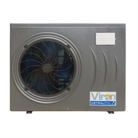
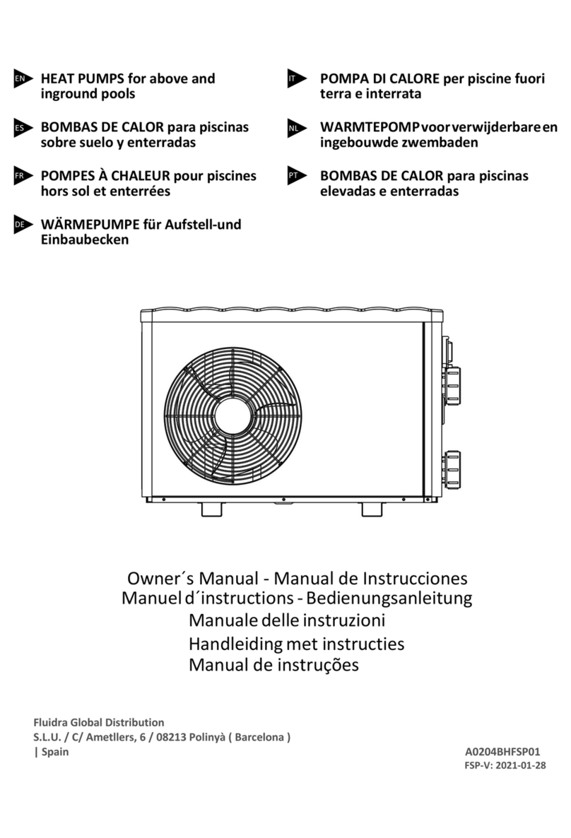
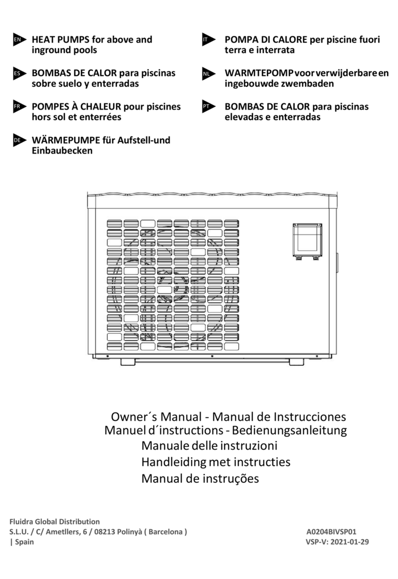
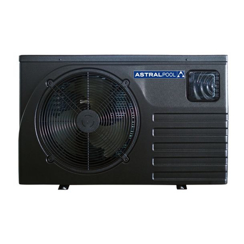
fluidra ASTRALPOOL Viron 78572 Service manual

3/08/2017
The appliance is not intended for use by young children o persons without supervision. Please ensure that
Bolero ND Cleaner
INSTALLATION AND OPERATING INSTRUCTIONS I INSTALLATION AND OPERATING INSTRUCTIONS
VIRON RANGE
INVERTER HEAT PUMPS
Installation & Instruction manual
Viron Range
Inverter Heat Pumps


CONTENTS
1. Preface
2. Specifications
2.1 Performance Data of Swimming Pool Heat Pump Unit
2.2 Dimensions for Swimming Pool Heat Pump Unit
3. Installation and Connection
1.3
2.3
3.3 How Close to Your Pool?
3.4 Swimming Pool Heat Pumps Plumbing
3.5 Swimming Pool Heat Pumps Electrical Wiring
3.6 Initial Start-up of the Unit
4. Operation and Use
1.4
2.4
3.4
4.4
5. Maintenance and Inspection
6.Appendix
Installation illustration
Swimming Pool Heat Pumps Location
Color screen wire controller interface introduction
Color screen wire controller function introduction
Parameter list and breakdown table
Interface drawin
6.1 Cable specification
6.2 Comparison table of refrigerant saturationtemperature
1
4
4
7
9
9
10
10
11
12
12
13
13
14
21
23
28
33
33
34

1. PREFACE
In order toprovide our customers with quality, reliability and versatility, this product has
been made tostrict production standards. This manual includes all thenecessary
information about installation,debugging, discharging and maintenance. Please read this
manual carefully beforeyou open or maintain the unit. The manufacture of this productwill
not be heldresponsible if someone is injured or the unit is damaged, as aresult of
improper installation, debugging,or unnecessary maintenance. It is vital that the
instructions within this manual are adhered to at all times. The unit must be installed by
qualified personnel.
The unit canonly be repaired by qualified installer centre , personnel or an authorised
dealer.
Maintenance and operationmust be carried out according to the recomended time and
frequency, as stated inthis manual.
Use genuine standardspare parts only.
Failure to complywith these recommendations will invalidate the warranty.
Swimming Pool HeatPump Unit heats the swimming pool water and keeps the temperature
constant. For splittype unit, The indoor unit can be Discretely hidden or semi-hiddento
suit a luxuryhouse.
Our heat pumphas following characteristics:
1 Durable
The heat exchanger is madeof PVC & Titanium tube which can withstandprolonged
exposure to swimmingpool water.
2 Installation flexibility
The unit can be installed outdoors.
3 Quiet operation
The unit comprises an efficient rotary/ scrollcompressor and alow-noise fan motor,
which guarantees itsquiet operation.
4 Advancedcontrolling
The unit includes micro-computer controlling,allowing all operation parameters to be
set. Operation statuscan be displayed on the LCD wire controller. Remote controller canbe
chosen as futureoption.
1
WARNING
Do not usemeans to accelerate the defrosting process or to clean,
Other than thoserecimmended by the manufacturer.
The appliance shallbe stored in a room without continuously operating ignition sources
(for example:open flames,an operating gas appliance or an operating electric heater.)
Do not pierceor burn.
Be aware thatrefrigerants may not contain an odour,
Appliance shall beinstalled,operated and stored in a room with a floor area larger thanX .
NOTE The manufacturer may provideother suitable examples or may provide additional
information about therefrigerant odour.

This appliance can be used by children aged from 8 years and above and persons
with reduced physical, sensory or mental capabilities or lack of experience and
knowledge if they have been given supervision or instruction concerning use of the
appliance in a safe way and understand the hazards involved. Children shall not play with
the appliance. Cleaning and user maintenance shall not be made by children without
supervision.
The appliance shallbe installed in accordance with national wiring regulations.
If the supply cord is damaged, it must be replaced by the manufacturer, its service agent or
similarly qualified personsin order to avoid a hazard.
Before obtaining accessto terminals, allsupply circuits must be disconnected.
Do not operateyour air conditioner in a wet room such as a bathroom orlaundry room.
An all-pole disconnection device which has at least 3mm clearances in all pole
have a leakage current that may exceed 10mA residual current device (RCD) having
a rated residual operating current not exceeding 30mA disconnection must be
incorporated in thefixed wiring in accordance with the wiring rules
1. PREFACE
2
Do not use means to accelerate the defrosting process or to clean, other than those
recommended by themanufacturer
The appliance shall be stored in a room withoutcontinuously operating ignition sources (for
example: open flames,an operating gas appliance or an operating electric heater.)
Do not pierceor burn
Appliance shall beinstalled, operated and stored in a room with a floor area largerthan X
m2
Be aware thatrefrigerants may not contain an odour.
The installation ofpipe-work shall be kept to a minimum X m2
Spaces where refrigerantpipes shall be compliance with national gas regulations.
Servicing shall beperformed only as recommended by the manufacturer.
The appliance shallbe stored in a well-ventilated area where the room size corresponds to
the room areaas specified for operation.
All working procedurethat affets safety means shall only be carried by competent persons.
Transport of equipment containing flammable refrigerants
Compliance with thetransport regulations
Marking of equipmentusing signs
Compliance with localregulations
Disposal of equipmentusing flammable refrigerants
Compliance with nationalregulations
Storage of equipment/appliances
The storage ofequipment should be in accordance with the manufacturer's instructions.
Storage of packed(unsold) equipment
Storage package protectionshould be constructed such that mechanical damage to the
equipment inside thepackage will not cause a leak of the refrigerant charge.
The maximum numberof pieces of equipment permitted to be stored together will be
determined by localregulations.

1. The unit can onlybe repaired by qualified installer centre personnel or an authorised
dealer. for Europe market
2. This appliance is notintended for use by persons (including children) with reduced physical
sensory or mentalcapabilities, or lackof experience and knowledge, unless they have been
given supervision orinstruction concerning useof the appliance by a person responsible for
their safety. for Europe market
Children should besupervised to ensurethat they do not play with the appliance.
3. Please makesure that theunit and power connection have good earthing, otherwise may
cause electrical shock.
4. If thesupply cord isdamaged, it must be replaced by the manufacturer or our service agent
or similarly qualifiedperson in orderto avoid a hazard.
5. Directive 2002/96/EC(WEEE):
The symbol depicting a crossed-outwaste bin that is underneath the appliance indicates
that this product,at the endof its useful life, must be handled separately from domestic
waste, must betaken to arecycling centre for electric and electronic devices or handed
back to thedealer when purchasingan equivalent appliance.
6. Directive 2002/95/EC(RoHs): This product is compliant with directive 2002/95/EC (RoHs)
concerning restrictions forthe use ofharmful substances in electric and electronic devices.
7. The unit CANNOT be installed near the flammable gas. Once there is any leakage of the gas
, fire canbe occur.
8. Make surethat there iscircuit breaker for the unit, lack of circuit breaker can lead to
electrical shock orfire.
9. The heat pump locatedinside the unit is equipped with an over-load protection system. It
does not allowfor the unit to start for at least 3 minutes from a previous stoppage.
10. The unit can onlybe repaired by the qualified personnel of an installer center or an
authorized dealer. for NorthAmerica market
11. Installation must beperformed in accordance with the NEC/CEC by authorized person only.
for NorthAmerica market
12. USE SUPPLY WIRES SUITABLE FOR 75 .
13. Caution: Singlewall heat exchanger, not suitable for potable water connection.
Caution & Warning
1. PREFACE
3

4
2.SPECIFICATION
2.1 Performance data of Swimming Pool Heat Pump Unit
*** REFRIGERANT : R32
See the drawingof the units
See package lable
see nameplate
see package label
Heating: Outdoor airtemp: 27 /24.3 , Inlet water temp:26
Outdoor air temp:15 /12 , Inlet water temp:26
Outdoor air temp:10 /6.8 , Inlet water temp:26
Operating range:
Ambient temperature:-15 43
Water temperature:9-40
UNIT
Heating capacity
(27/24.3
Heating Power Input
COP
Heating capacity
(15/12
Heating Power Input
COP
Heating capacity
(10/6.8
Heating Power Input
COP
Power Supply
Compressor Quantity
Compressor
Fan Number
Noise(1m)
Water Connection
Water Flow Volume
Water Pressure Drop(max)
Unit Net Dimensions(L/W/H)
Unit Ship Dimensions(L/W/H)
Net Weight
Shipping Weight
kW
Btu/h
kW
kW
Btu/h
kW
kW
Btu/h
kW
dB(A)
mm
3
m/h
kPa
mm
mm
kg
kg
78573
2.85~12
9690~40800
0.21~2.12
13.57~5.66
2.25~9.7
7650~32980
0.32~2.08
7.03~4.66
1.88~8
6392~27200
0.33~1.95
5.7~4.1
220-240V /50Hz
1
rotary
1
42-52
48.3
4.2
4.5
78572
2.15~9
7310~30600
0.16~1.6
13.44~5.63
1.75~7.4
5950~25160
0.25~1.6
7~4.63
1.42~6.1
4828~20740
0.25~1.5
5.68~4.07
220-240V /50Hz
1
rotary
1
40-50
48.3
3.2
4

5
2.SPECIFICATION
2.1 Performance data of Swimming Pool Heat Pump Unit
See the drawingof the units
See package lable
see nameplate
see package label
UNIT
Heating capacity
(27/24.3
Heating Power Input
COP
Heating capacity
(15/12
Heating Power Input
COP
Heating capacity
(10/6.8
Heating Power Input
COP
Power Supply
Compressor Quantity
Compressor
Fan Number
Noise
Water Connection
Water Flow Volume
Water Pressure Drop(max)
Unit Net Dimensions(L/W/H)
Unit Ship Dimensions(L/W/H)
Net Weight
Shipping Weight
kW
Btu/h
kW
kW
Btu/h
kW
kW
Btu/h
kW
dB(A)
mm
3
m/h
kPa
mm
mm
kg
kg
78575
4.6~19.5
15640~66300
0.37~3.94
12.43~4.95
3.84~15.4
13056~52360
0.6~3.81
6.4~4.04
3.38~14.4
11492~48960
0.62~3.62
5.45~3.98
220-240V /50Hz
1
rotary
1
45-56
48.3
6.6
6
*** REFRIGERANT : R32
Heating: Outdoor airtemp: 27 /24.3 , Inlet water temp:26
Outdoor air temp:15 /12 , Inlet water temp:26
Outdoor air temp:10 /6.8 , Inlet water temp:26
Operating range:
Ambient temperature:-15 43
Water temperature:9-40
78574
3.77~17
12818~57800
0.3~3.02
12.57~5.63
2.92~12.4
9928~42160
0.44~2.86
6.64~4.34
2.5~10.7
8500~36380
0.45~2.64
5.56~4.05
220-240V /50Hz
1
rotary
1
44-53
48.3
5.3
5

6
2.SPECIFICATION
2.1 Performance data of Swimming Pool Heat Pump Unit
*** REFRIGERANT : R32
See the drawing of the units
See package lable
see nameplate
see package label
UNIT
Heating capacity
(27/24.3
Heating Power Input
COP
Heating capacity
(15/12
Heating Power Input
COP
Heating capacity
(10/6.8
Heating Power Input
COP
Power Supply
Compressor Quantity
Compressor
Fan Number
Noise
Water Connection
Water Flow Volume
Water Pressure Drop(max)
Unit Net Dimensions(L/W/H)
Unit Ship Dimensions(L/W/H)
Net Weight
Shipping Weight
kW
Btu/h
kW
kW
Btu/h
kW
kW
Btu/h
kW
dB(A)
mm
3
m/h
kPa
mm
mm
kg
kg
78577
6.7~28.3
22780~96220
0.54~5.57
12.41~5.08
5.46~23.3
18564~79220
0.83~5.49
6.58~4.24
4.9~20.8
16660~70720
0.87~5.1
5.63~4.08
380-415V/3N /50Hz
1
rotary
1
48-58
48.3
10
15
Heating: Outdoor air temp: 27 /24.3 , Inlet water temp:26
Outdoor air temp:15 /12 , Inlet water temp:26
Outdoor air temp:10 /6.8 , Inlet water temp:26
Operating range:
Ambient temperature:-15 43
Water temperature:9-40
78576
5.7~24.2
19380~82280
0.46~4.8
12.39~5.04
4.68~19.9
15912~67660
0.72~4.74
6.5~4.2
4.2~17.8
14280~60520
0.75~4.4
5.6~4.05
220-240V /50Hz
1
rotary
1
46-57
48.3
8.6
11

2.2 The dimensions for Swimming Pool Heat Pump Unit
UNIT:78572/78573
unit mm
2.SPECIFICATION
7
UNIT:78574/78575
unit mm
Water inlet
48.3
Water outlet
48.3
465
7
9
5.2
68
790
470
1161
768
1046
615
435
Water inlet
48.3
Water outlet
48.3
350
011

2.SPECIFICATION
8
2.2 The dimensions for Swimming Pool Heat Pump Unit
unit mm
UNIT:78576/78577
4
721
1161
775
470
Water inlet
48.3
Water outlet
48.3
0
55
97

9
Installation items:
The factory only provides the main unit and the water unit; the other items in the illustration
are necessary spare parts for the water system ,that provided by users or the installer.
3.1 Installation illustration
Attention:
Please follow these steps when using for the first time
1.Open valve and charge water.
2.Make sure that the pump and the water-in pipe have been filled with water.
3.Close the valve and start the unit.
ATTN: It is necessary that the water-in pipe is higher than the pool surface.
3.INSTALLATION AND CONNECTION
The schematic diagram is for reference only. Please check the water inlet/outlet label on the
heat pump while plumbing installation.
The schematic diagram is for reference only. Please check the water inlet/outlet label on the
heat pump while plumbing installation.
The controller is mounted on the wall
IMPORTANT NOTE:
A WATER BY-PASS MUST BE PLUMBED TO REGULATE WATER FLOW TO HEAT PUMP.
FAILURE TO DO SO MAY RESULT IN POOR EFFICIENCY AND REDUCED HEATING OUTPUT.

10
3.INSTALLATION AND CONNECTION
The unit willperform well in any outdoor location provided that the following three factorsare
presented:
1. Fresh Air - 2. Electricity - 3. Pool filter piping
The unit maybe installed virtually anywhere outdoors. For indoor pools please consult the
supplier. Unlikea gas heater, it has no draft or pilot light problem in a windyarea.
DO NOT place the unitin an enclosed area with a limited air volume, where the units
discharge air willbe re-circulated.
DO NOT place the unitto shrubs which can block air inlet. These locations deny theunit of a
continuous source offresh air which reduces it efficiency and mayprevent adequate heat
delivery.
3.2 Swimming Pool Heat Pumps Location
Normally, the pool heatpump is installed within 7.5 metres of the pool. The longer the
distance from thepool, the greaterthe heat loss from the piping. For the most part ,the piping
is buried. Therefore, the heatloss is minimal for runs of up to15 meters(15 meters to andfrom
the pump =30 meters total),unless the ground is wet or the water table is high.A very rough
estimate of heatloss per 30 meters is 0.6 kW-hour,(2000BTU) for every 5 difference in
temperature between thepool water and the ground surrounding the pipe, which translates to
about 3% to5% increase in run time.
3.3 How Close To Your Pool?
Air inlet
Air outlet
1500mm
700mm
300mm
500mm
700mm

3.INSTALLATION AND CONNECTION
11
3.4 Swimming Pool Heat Pumps Plumbing
Location: Connect the unit in the pool pump discharge (return) line downstream of all filter
and pool pumps, and upstream of any chlorinators, ozonators or chemical pumps.
Standard model have slip glue fittings which accept 32mm or 50 mm PVC pipe for
connection to the pool or spa filtration piping. By using a 50 NB to 40NB you can plumb 40NB
Give serious consideration to adding a quick coupler fitting at the unit inlet and outlet to allow
easy draining of unit for winterizing and to provide easier access should servicing be
required.
Condensation: Since the Heat pump cools down the air about 4 -5 , water may condense on
the fins of the horseshoe shaped evaporator. If the relative humidity is very high, this could
be as much as several litres an hour. The water will run down the fins into the basepan and
drain out through the barbed plastic condensation drain fitting on the side of the basepan.
This fitting is designed to accept 20mm clear vinyl tubing which can be pushed on by hand
and run to a suitable drain. It is easy to mistake the condensation for a water leak inside the
unit.
NB: A quick way to verify that the water is condensation is to shut off the unit and keep the
pool pump running. If the water stops running out of the basepan, it is condensation. AN
EVEN QUICKER WAY IS to TEST THE DRAIN WATER FOR CHLORINE - if the is no chlorine
present, then it's condensation.
To pool
From pump
PVC COUPLER
RECOMMENDED(Provided)
CONDENSATION
DRAIN
BARB FTG
The Swimming Pool Heat Pumps exclusive rated flow titanium heat exchanger requires no
special plumbing arrangements except bypass(please set the flow rate according to the
nameplate). The water pressure drop is less than 10kPa at max. Flow rate. Since there is no
residual heat or flame Temperatures, The unit does not need copper heat sink piping. PVC
pipe can be run straight into the unit.
IMPORTANT NOTE:
A WATER BY-PASS MUST BE PLUMBED TO REGULATE WATER FLOW TO HEAT PUMP.
FAILURE TO DO SO MAY RESULT IN POOR EFFICIENCY AND REDUCED HEATING OUTPUT.

3.5 Swimming Pool Heat Pumps Electrical Wiring
NOTE: Althoughthe unit heat exchanger is electrically isolated from the rest of the unit, it
simply prevents theflow of electricityto or from the pool water. Grounding the unit is still
required to protectyou against shortcircuits inside the unit. Bonding is also required.
3.INSTALLATION AND CONNECTION
3.6 Initial startup of the Unit
NOTE- In orderfor the unit to heat the pool or spa,the filter pump must be running to
circulate water throughthe heat exchanger.
Start up Procedure- After installation is completed, you should followthese steps:
1. Turnon your filter pump. Check for water leaks andverify flow to and from the pool.
2. Turnon the electrical power supply to the unit, thenpress the key ON/OFF of wire
controller, Itshould start in several seconds.
3. Afterrunning a few minutes make sure the air leavingthe top(side) of the unit is
cooler(Between 5-10 )
4. With theunit operating turn the filter pump off. The unit should also turn off automatically,
5. Allowthe unit and pool pump to run 24 hoursper day until desired pool water temperature
is reached. Whenthe water-in temperature reaches this setting, the unit willslow down for a
period of time,if the temperature is maintained for 45 minutes theunit will turn off. The unit
will now automaticallyrestart (as long as your pool pump is running)whenthe pool
temperature drops morethan 0.2 below set temperature.
Time Delay- The unit is equipped witha 3 minute built-in solid state restart delay includedto
protect control circuitcomponents and to eliminate restart cycling and contactor chatter.
This time delaywill automatically restart the unit approximately 3 minutes aftereach control
circuit interruption. Evena brief power interruption will activate the solid state3 minute
restart delay andprevent the unit from starting until the 5 minutecountdown is completed.
The unit hasa separate molded-in junction box with a standard electricalconduit nipple
already in place.Just remove the screws and the front panel, feedyour supply lines in
through the conduitnipple and wire-nut the electric supply wires to thethree connections
already in thejunction box (four connections if three phase). To complete electrical hookup,
connect Heat Pumpby electrical conduit, UF cable or other suitable meansas specified (as
permitted by localelectrical authorities) to a dedicated AC power supplybranch circuit
equipped with theproper circuit breaker, disconnect or time delay fuseprotection.
Disconnect -A disconnect means (circuit breaker , fused orun-fused switch) should be
located within sightof and readily accessible from the unit, This is common practice on
commercial and residentialair conditioners and heat pumps. It prevents remotely-energizing
unattended equipment andpermits turning off power at the unit while the unit is being
serviced.
12

4.Operationanduse
4.1
Color screen wire controller interface introduction
4.1.1Maininterface
4.1.2ButtonDescription
NO. Name The button function
ON/OFF Press to start /shut off the unit
Parameter Click this button to view the unit state
and the parameter
CLOCK Press to set the clock,
the timer on or timer off
Fault display Click to view fault history
Silent setting Click to turn on/off silent function and to set
timingLow speed function.
MODE Click to enter the mode switch interface
Temp.curve Click to view the temp. and power curve
Water
Inlet Temp.
Click to enter mode setting and the target
temp. Setting interface
LOCK Click to lock the screen Input "22" to unlock
the screen by press the "lock button"
13

4.2
Color screen wire controller function introduction
4.2.1Bootin
g
and shutdown
As shown in figure 1.1:
In shutdown status, click then the unit will be booted
In booting status, click then the unit will be shut
down.
4.2.2Modeswitchandtar
g
et tem
p
erature Settin
g
2.2 1 Mode switch
In the main interface, click mode button or inlet water temperature setting
button, interface displays as follows:
28.0
Click the refrigeration mode button , automatic mode or
heating mode button then you can select the corresponding mode.
Note: when the unit is designed for single automatic mode or single
thermal mode, the mode can not be switched.
2.2
2Target temp. setting
Click the temperature set button , you can set the target temperature.
14
4.Operationanduse

15
4.2.3
Clock settin
g
In the main interface, click on the clock Settin
g
s button,
interface displays as follows:
2.3.1
The operation of time settin
g
Click on the time Settings button ,interface displays as follows:
Click the value to set time directly, the click confirm button to save the
Settings.
For example: setup time: the 30-11-2016 16:00:00, input 30 11 16 16 00 00 , the
time change then click confirm button.
Note: if the input format is not correct, the wrong time will be saved by
clicking confirm button.
4.Operationanduse

16
2.3.2
The operation of timin
g
settin
g
Click the timing set button timing setinterface.
NO. Name Button color Button function
Timing start
bu tton
Start: green
End: gray Click this button to start or end
timing start setting function
Timing on
setting Click to set start time of the timing
Timing end
button
Open: red
End: gray Click this button to start or end
tim ing end s etting function
Timing off
setting Click to set end time of the timing
For example above: without action, 0 o 'clock and 1o 'clock will
be the on and off time of timing settings.
4.Operationanduse

17
4.2.4
Silent setting and silent timing setting
Click the silent setting button ,and the interface displays as follows:
2.4.1
The silent button
Click the silent button , the unit will enter the silent mode,
and interface displays as follows:
Click the silent button again, to exit the silent mode.
4.Operationanduse
This manual suits for next models
7
Table of contents
Other fluidra Heat Pump manuals
Popular Heat Pump manuals by other brands

Lennox
Lennox 13HPX Brochure & specs

Aquacal
Aquacal Heat Pump installation guide

Carrier
Carrier Weathermaster III 38HQ Installation, Start-Up and Service Instructions

Nibe
Nibe F1355 Series Installer manual

Viessmann
Viessmann VITOCAL 300 Installation and service instructions

Trane
Trane IC-IH 039 Installation operation & maintenance