INST 412 UF ULTRA FINE Cartridge Filter V10-17
GENERAL INSTALLATION INFORMATION.
The following information should be read carefully as it outlines the proper manner of care and operation of your filter
system. You can expect maximum efficiency and product life from you filtration system by following these instructions and
taking the necessary preventative maintenance.
*.Have a trainer pool professional perform all pressure testing
* Do not connect the system to a high pressure or city water systems.
* Trapped air in the system can create a hazardous condition. MAKE SURE to purge all air from the system before operating
or testing of the equipment.
* DO NOT PRESSURE TEST WITH COMPRESSED AIR
* Check local codes for restrictions on backwash to waste piping, separation tank requirements.
*Piping must conform to local/state plumbing and sanitary codes
*Support piping independently to prevent strains on the filter or valve
* Fittings restrict flow, for best efficiency, use the fewest possible fittings
* a check valve installed between the filter inlet will prevent contaminants from draining back into the Pool.
* A check valve installed between the filter and heater will prevent hot water from backing up into the filter and deforming
the internal components.
* All wiring, grounding and bonding of associated equipment must meet local and/or National Electrical Code (NEC)
standards
GENERAL OVERVIEW
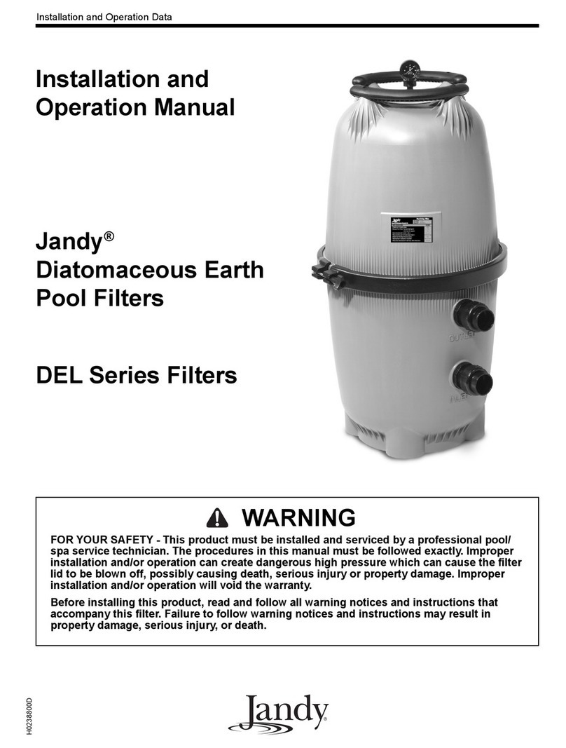
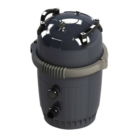
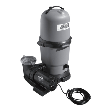
The Astralpool UF Cartridge filter features 4 easily accessible and removable filter cartridges. When water passes through
these cartridges, microscopic impurities like dirt, algae and some forms of bacteria are filtered out, giving you water that
really sparkles.
The 4 cartridges design greatly increases the filter’s internal surface area, meaning a much greater cleaning capacity for every
cycle without the need for a larger filter. Cleaning couldn’t be easier, just simply removing the clamp band and lifting the lid
off. To access the 4 cartridges.
INSTALLATION
Only a Qualified service person should install the Astralpool UF Cartridge filter.
WARNING –Risk of electrical shock or electrocution.
Position the filter and allowing for the air/water bleed valve located in the lid to safely direct water drainage and purged air
or water. Water discharged from an improperly position filter can create an electrical hazard that can cause severe personal
injury as well as damage property.
WARNING –THIS FILTER OPERATES UNDER HIGH PRESSURE
Never subject the filter to pressure in excess of the maximum working pressure, even when conducting hydrostatic
pressure testing. Pressures above the maximum working psi pressures can cause the lid to be blown off. Which can result in
severe injury, death or property damage
1. The filter should be mounted on a level concrete slab. Position the filter so that the instructions, warning and
pressure gauge are visible to the operator. It should also be positioned so that the piping connections, control valve
and drain port are convenient and accessible for servicing and winterizing.
2. Install electrical controls (timers, Chlorinators, power points) at least 6 feet from the filter. This will allow you
enough room to stand clear of the filter during start up.
3. Allow sufficient clearance around the filter to allow visual inspection of the clamp is correctly installed around the
tank flanges. Using a soft mallet tap the clamp to ensure uniform loading during the clamp tightening.
4. Allow enough space above the filter to remove the filter lid for cleaning and servicing. This distance should be a
minimum of 2 feet
5. The Astralpool UF Cartridge filter has 1 inlet, 2 outlets and a drain port. Either inlet can be used (top inlet height
for other brands heaters, bottom inlet to suit HINRG 175,HiNRG 250 or HiNRG 400 heater. Whichever port you
use the other will have to be plugged with plug cap supplied with filter
6. Make all plumbing connections in accordance with local plumbing and building codes. Check local codes for
restrictions on backwash to waste piping, separation tank requirements. Allow minimum of 1 hour for glue to dry
on pipe fittings before pressuring up the system.
7. Filter plumbing connections are provided with an o-ring seal to avoid damage to the o-rings, use only a silicone base
lubricant on the o-rings. Do not use a petroleum based lubricate as it it degrade the o-rings.
8. Install the pressure gauge (supplied with the filter) into the marked hole in the lid, using Trflon tape on the gauge
thread.
9. If the filter is installed below water level, isolation valves must be installed on the inlet & outlet to enable the filter
to be dismantled for cleaning without the loss of water from the pool or spa.
10. It is recommended that a 3 way valve be installed on the return line to allow draining of water from the pool or spa
when necessary.
11. The maximum working pressure of this filter is 50 psi. Never subject this filter to pressure in excess of the amount,
even when conducting hydrostatic pressure testing. Pressures above 50 psi can cause the lid to be blown off, which
can result in severe injury, death or property damage
