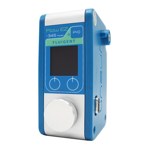
Fluigent LineUp Series User manual

USER’S
MANUAL
LINEUPTM SERIES

Push-Pul lPush-Pull
QUICK START GUIDE
LineUp Flow EZTM
Pressure controller
LineUpTM Push-Pull
Pressure controller
Aria is a perfusion system which automates perfusion or timed
injection protocols. It allows for the sequential delivery of up to 10
different solutions at the desired flow rate into a microfluidic chip,
perfusion chamber or petri dish.
The quick start guide is a forward to the LineUpTM Series user's manual

3
A -
QUICK START GUIDE
1Supplied (inlet) pressure from pump or compressed air supply
2Power supply to the Flow EZTM / Push-Pull pressure controller
3Regulated (outlet) pressure from pressure controller to reservoir
4Pressurized reservoir P-CAP
5Microfluidic set-up in example a microfluidic chip
1
2
4
3
5
1. The Flow EZTM/ Push-Pull regulates the externally supplied
(inlet) pressuretoauser-definedpressurewithhighprecision.
2. Thisregulated(outlet)pressurepressurizesthereservoir,
driving the liquid up through the tubing and into the
microfluidicsetup.
3. Controllingtheoutletpressureallowsonetocontroltherate
atwhichfluidisinjectedintothemicrofluidicsetup.

4
W
QUICK START GUIDE
Contained in the package
Flow EZTM or Push-Pull Outlet tubing (OD 4mm)
*OD: Outer diameter
P-CAP Kit or Fluiwell Kit (sold separately)
P-CAP (or Fluiwell) reservoir
Fluiwell: for 15mL or 50mL reservoirs
P-CAP for 2mL, 15mL or 50mL reservoirs
Fluidic tubing
Outer diameter and inner diameter
depending on the Kit

5
QUICK START GUIDE
LineUpTM supply Kit (sold separately)
Inlet tubing (OD: 6mm)
Power supply (24VDC)
Power supply to Sub-D adaptor
*OD: Outer diameter

6
P
QUICK START GUIDE
Oncepoweredon,theFlowEZTMor
Push-Pull willdisplaythe "Inlet
pressure check window",givingthe
measuredpressureattheinlet
(P inlet)andthesupplypressure
requiredtooperatethepressure
controller (Ptarget).
For example, left shows a 1000 mbar
range Flow EZTM
P target : 1100 mbar
P inlet : 0 mbar
Note : For the 7000 mbar range as
well as negative pressure ranges
Flow EZTM, this window will not appear.
To wall socket

7
P
QUICK START GUIDE
The Flow EZTM or Push-Pull
needs an external pressure
supply to operate. This can be
a lab's compressed air supply,
an air compressor, or any
clean(filtered< 10 µm)anddry
compressed air supply.
Different Flow EZTM ranges
require different supply
pressures(showntotheright).
Note : If one intends to use compressed gas other than air, or if the pressure
supply is out of the pressure range requirements, please contact Fluigent.
Always wear safety protection
when manipulating pressure.
- For positive range, never
exceed 8 bar (120 psi)
- For negative range, never
connectanypositivepressure
Pressure supply
Flow EZTM
range (mbar)
Required pressure
supply (mbar)
7000 7100
2000 2100
1000
1100
345
69
150
25
-25
-800
-69
-345
-800

8
The Push-Pull module works the same way as other Flow EZTM modules,
except that it can output pressure (above atmospheric pressure)
and vacuum (below atmospheric pressure) through the same port.
P-P
Note : Depending on the supply pressures, the performance of
the module can vary, especially for the vacuum pressure supply.
When connecting the two supplies, only the positive pressure supply
will be checked on the "Inlet pressure check window". (see page 10)
Push-Pull output (mbar) Required pressure supply (mbar)
1000 1100
-800 -800
QUICK START GUIDE
Positive pressure
supply inlet
Vacuum
supply inlet
Pressure /
Vacuum outlet
To do so, it needs two inlets: the positive one, uses the standard pressure
supply of the Flow EZTM, and the negative one, utilizes an additional
connector located at the front between the FLOW UNIT port and the
"unlock" handle.
Ensure to power ON the LineUpTM Push-Pull and set the pressure
value on 0 mbar before connecting the vacuum supply.
Special attention
should be taken to
preventliquidfrom
flowing back into
the module.

9
QUICK START GUIDE
A Push-Pull module can be combined with other positive
pressure LineUPTM modules the same way as a Flow EZTM
1 bar. If connecting to higher pressure modules, please
consider adding an Adapt module to reduce the
positive pressure supply. (See page 29 for more details)
When using a Push Pull module, care should be taken to
avoid drawing liquid into the system. This can seriously
damage the module. It is advised to use a liquid filter
between the outlet and the reservoir as it reduces the risks.
Note: The pressure supply is mandatory for the use of the Push-Pull even
in vacuum mode only. The vacuum supply is optionnal.
Please, never stack a Push-Pull module with a negative Flow EZTM as it
would not work.

10
A
(A 1000 mbar range Flow EZTM is shown as an example)
Adjust the pressure
from your
pressure source
The P inlet value
is displayed in
red
The P inlet value
is displayed in
green
When connecting the pressure supply, if its value (P inlet) is not set at
the required value (P target), the Flow EZTM or Push-Pull will continue to
display the "Inlet pressure check window" (with the exception of the 7000
mbar range and the negative ranges which don't have this window)
If the value is displayed in red, please adjust the pressure supply.
When the two values are close enough, the P inlet value will turn green
and the display on the Flow EZTM or Push-Pull will transition to "Operation
window"
QUICK START GUIDE

11
QUICK START GUIDE
O
Pause button
Press to bring outlet
pressure to zero
Press again to
recover pressure
Hold to enter sleep
mode
Pmeas
Measurement of
the pressure in the
reservoirs
Product name and
pressure range
Open menu
Unit can be
changed using the
menu
Rotates display
Pcmd
User-defined
pressure command
The pressure sensor inside the Flow EZTM or Push-Pull device
needs to be calibrated before the first use (see next page).
If the system isn't calibrated, the outlet measured pressure (Pmeas) may
be incorrect.

12
P
1. Press "Menu"
2. Use the dial (turn and press) to select "Pressure calibrate"
3. Wait a few seconds
4. The calibration is done
Note: Due to the high sensitivity of the internal pressure sensor,
one may observe some small fluctuations of the measured
pressure (Pmeas), even after the calibration is complete.
An example of
Pmeas before
calibration
Calibrating ...
10
1
3
2
4
QUICK START GUIDE

13
C
QUICK START GUIDE
P-CAP (or Fluiwell)
and reservoir
Microfluidic setup
FLOW UNIT (sold separately)
Aria is a perfusion system which automates perfusion or timed
injection protocols. It allows for the sequential delivery of up to 10
different solutions at the desired flow rate into a microfluidic chip,
perfusion chamber or petri dish.
One can connect a FLOW UNIT (Fluigent flow sensor) between the
reservoir and the microfluidic setup. (See page 22 for more details)

14
W F EZTM / P-P
QUICK START GUIDE
If one needs to disconnect the power supply (e.g. to move or store the
unit), please make sure the Flow EZTM or Push-Pull is already in sleep
mode before disconnecting the power.
When one has finished using the Flow EZTM or Push-Pull, hold
the "P=0" button in order to put the device into sleep mode.
Thisprocedurewillreleaseallresidualpressureinthesystem,preventing
any further pressure from being appliedtoyourfluidicsetup.
Forafullydetailedshutdownprocedure,pleaseseepage 32.
1
2

15
The Flow EZTM or Push-Pull is ready to be used,
Simply turn the dial to start.
The user's manual in on the next page:
Allowing one to get the most out of the LineUpTM series devices.


PRODUCT OVERVIEW 18
SETTING UP 21
A faster way to change the pressure 21
Add a FLOW UNIT 22
Flow rate control 24
Inject a volume 25
Flow-related setting 26
Liquid type 27
SYSTEMEXPANSION 28
Create a multi-channel configuration 28
Mixing different pressure range 29
LineUpTM Adapt 30
COMPUTER CONNECTION 31
LineUpTM Link 31
LineUpTM Link COM 32
SHUTDOWN PROCEDURE 36
ADDITIONAL FEATURES 37
FREQUENTLY ASQUED QUESTIONS FAQ 38
WARRANTY TERMS 40
TECHNICAL SUPPORT 41
LINEUPTM SERIES
USER’S MANUAL

18
1FLOW UNIT port to the flow sensor
2Pressure supply transmission used only in multi-channel configuration
3Pressure outlet to reservoir
4Pressure inlet from pump or compressed air supply
3
2
1
PRODUCT OVERVIEW
LineUp Flow EZTM
Pressure controller
4

19
PRODUCT OVERVIEW
LineUp Push-Pull
Pressure controller
1FLOW UNIT port to the flow sensor
2Pressure supply transmission used only in multi-channel configuration
3Pressure outlet to reservoir
4Positive pressure inlet from pump or compressed air supply
5Vacuum inlet from vacuum pump
3
2
1
4
5

20
1Unlock button used only in multi-channel configuration
2P=0 button press once to set pressure to 0, press again to return to original
pressure, hold to put into sleep mode
3Left button press to rotate the display/go back
4Right button press to open the menu/enter
5Power / Data connection provide power supply and data connection
6Power / Data transmission used only in multi-channel configuration
7Dial for local control
1
3
5
2
4
6
7
PRODUCT OVERVIEW
Change pressure command
Navigate in menu
Set/Apply pressure
Command set in menu
Other manuals for LineUp Series
1
This manual suits for next models
2
Table of contents
Other Fluigent Controllers manuals
