Fluke GBK-50M User manual

PN 5007320
July 2018
©2018 Fluke Corporation. All rights reserved.
All product names are trademarks of their respective companies. Specifications are subject to change without notice.
Fluke Corporation
P.O. Box 9090
Everett, WA 98206-9090
U.S.A.
Fluke Europe B.V.
P.O. Box 1186
5602 BD Eindhoven
The Netherlands
ООО «Флюк СИАЙЭС»
125167, г. Москва, Ленинградский
проспект дом 37,
корпус 9, подъезд 4, 1 этаж
1
GBK-50M / GBK-110M
Booster
Instructions
Introduction
The GBK-50M and GBK-110M (the Product) are gas booster packages that provide the required gas-pressure
supply needed by the Fluke Calibration 8270A and 8370A controller/calibrators.
Both models include a pneumatically driven, piston type, self-cycling gas booster with regulated output to provide the
8270A and 8370A high-pressure supply. The gas booster boosts a lower pressure usually supplied from a bottle, to
higher pressure. The high-pressure gas is stored in an accumulator volume to assure stable supply to the 8270A
and 8370A.
GBK-50M has a maximum output pressure of 61 MPa (8850 psi).
GBK-110M has a maximum output pressure of 124 MPa (18 000 psi).
How to Contact Fluke Calibration
To contact Fluke Calibration, call one of the following telephone numbers:
Technical Support USA: 1-877-355-3225
Calibration/Repair USA: 1-877-355-3225
Canada: 1-800-36-FLUKE (1-800-363-5853)
Europe: +31-40-2675-200
Japan: +81-3-6714-3114
Singapore: +65-6799-5566
China: +86-400-810-3435
Brazil: +55-11-3759-7600
Anywhere in the world: +1-425-446-6110
To see product information and download the latest manual supplements, visit Fluke Calibration’s website at
www.flukecal.com.
To register your product, visit http://flukecal.com/register-product.

GBK-50M GBK-110M
Instructions
2
Safety Information
A Warning identifies conditions and procedures that are dangerous to the user. A Caution identifies conditions and
procedures that can cause damage to the Product or the equipment under test.
WWarning
To prevent personal injury:
Read all safety information before you use the Product.
Wear eye protection.
Use the Product only as specified, or the protection supplied by the Product can
be compromised.
Carefully read all instructions.
Do not use the Product if it operates incorrectly.
Do not use the Product if it is altered or damaged.
Disable the Product if it is damaged.
Do not attempt to operate the Product above its rated pressure.
Use care when working with this Product. Do not drop the product or strike it with
sharp objects.
This Product generates high-pressure gas and is used to regulate a high-gas
pressure output. Precautions need to be taken during installation and operation of
the Product.
Pressurized equipment is potentially dangerous. The Product generates and
controls very high-gas pressures. Do not operate the Product unless you
thoroughly familiarize yourself with these instructions. Additional training in
general and pressure specific safety procedures will help assure protection from
harm or damage to personnel or property.
Do not use oxygen. The Product is not compatible with the use of oxygen.
Hydrocarbon elastomers and lubricants are present.
High-pressure liquids and gases are potentially hazardous. Energy stored in these
liquids and gases can be released unexpectedly and with extreme force. High-
pressure systems should be assembled and operated only by personnel who have
been instructed in proper safety practices.
Symbols
The symbols shown in Table 1 are found in these instructions.
Table 1. Symbols
Symbol Definition
W WARNING, RISK OF DANGER.
Consult user documentation.
) Certified by CSA Group to North American safety standards.

Booster
Unpack the Product
3
Unpack the Product
The Product is delivered wrapped in plastic film and secured in a wooden crate. All ports are plugged, the drive air
valve is closed and pressure regulators are set to zero.
1. Remove the Product from the shipping crate and plastic. Take care not to lose or discard the items that are
included.
2. Remove all plastic plugs from the fittings and inspect for damage and contamination.
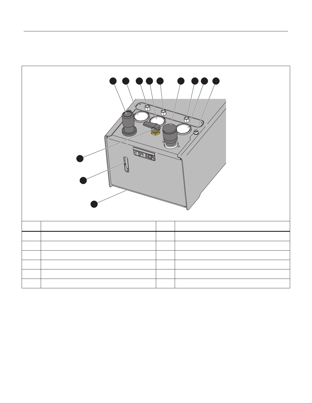
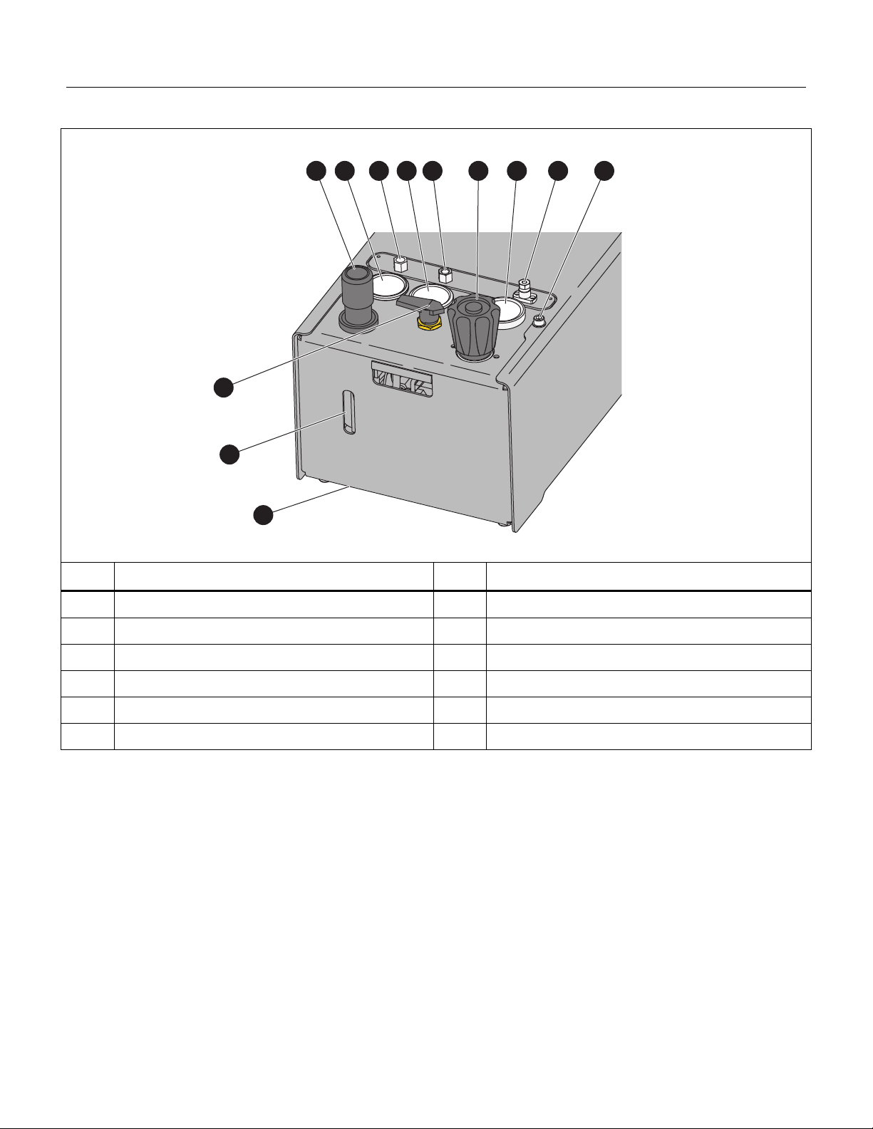
3. Inspect for any missing components or accessories. See Table 2. Should any items be missing, contact Fluke
Calibration or your local supplier.
Table 2. Parts List
Qty Description
2 Fitting, 1/4 NPT Male to hand-tight M16x2.0 w/Safety Caps, Steel
1 Hose, Microbore, 2 mm ID, M16F to M16F, 9100 PSI, 80 in, Hand-tight Fittings
1 Hose, Industrial QC, Brass 1/4 Socket x Steel 1/4 Plug, 3/8 in ID, 3 m, 10 ft
1 Fitting, Adapter (Hose Socket), QC x 1/4 NPT Male End, 1/4 Coupling Size, Brass
1 Fitting, Adapter (Hose Plug), QC Stem x 1/4 NPT Male End, 1/4 Coupling Size, Brass
Site Requirements
Two sources of compressed gas are required to operate the Product:
Shop drive air supply to power the booster
High-pressure gas that the booster compresses to higher pressures
Due to the different flow rate and cleanliness requirements for each of these supplies, they should come from two
separate sources. Fluke Calibration recommends that hazardous gases not be used.
Shop Air Drive Supply
The shop air drive supply powers the booster. The booster high-pressure output is approximately 75 times (GBK-
50M) or 152 times (GBK-110M) the drive air supply assuming that the test gas supply pressure is high enough. For
example, for a 700 kPa (100 psi) drive air supply, the GBK-50M will generate a maximum pressure of 52.5 MPa
(7500 psi) whereas a GBK-110M booster will generate 106.4 MPa (15 200 psi) of output pressure.
Note
Because the booster package includes an accumulator and high-pressure regulator, it is
preferable to generate the highest pressure that can be achieved and regulate it down to the
appropriate supply pressure for the 8270A or 8370A range to which the booster is connected.
The higher the pressure in the accumulator and upstream of the high-pressure regulator, the
greater the reserve of high pressure to assure a stable supply of pressure to the 8270A or
8370A.
Recommended Flow Rate: up to 2280 L/min (81 cfm) Free Air Delivery (FAD). FAD is at 20 C and 101 kPa
absolute (70 F and 14.7 psia). Flow rate at booster's typical inlet pressure of 700 kPa (100 psi) is up to
330 L/min (11.6 cfm).
Cleanliness: Not critical, system includes a filter
Humidity: 20 % to 50 % RH. Do not use dry gas or hazardous gases. Dry drive air will prematurely wear the
booster seals.

GBK-50M GBK-110M
Instructions
4
High-pressure Gas Supply
High-pressure product gas is boosted and supplied to the 8270A or 8370A SUPPLY port.
High-pressure instrument gas supply requirements are:
Pressure: Minimum recommended supply pressure is 4 MPa (600 psi) for the GBK-50M and 7 MPa (1000 psi)
for the GBK-110M. Lower supply pressures, >2 MPa (300 psi) for the GBK-50M and 4 MPa (600 psi) for the
GBK-110M, could be used for test excursions to lower pressures and minimal volumes. Avoid continuous
booster cycling (due to low-supply pressures) that exceeds 2-3 minutes. Maximum allowable supply pressure is
41 MPa (6000 psi).
Flow rate: 140 slm@0 C (5 scfm@32 F) minimum
Gas quality: Use clean, dry, non-corrosive instrument-grade gases only. Fluke Calibration recommends filtration
of 10 micron with a dew point of -20 C to 5 C. Inlet gas temperature should be between 10 C and 47 C.
Installation and Setup
Product installation depends on the specific application.
Consider these factors when you determine where to locate the Product:
The high pressure being generated and associated safety concerns
The source of gas supplies (drive air supply and high-pressure instrument gas supply)
Noise level
Access to the unit for operation of the regulators and valve
Point of use of output pressure

Booster
Installation and Setup
5
Note
Numerical references in this section refer to Table 3 or Table 4, depending on the model.
Table 3. GBK-50M
2 3 4 5 6 7 8 9
10
1
11
12
Iez001.eps
No. Description No. Description
Drive air supply regulator G HIGH PRESSURE OUT port
Regulated booster drive pressure gauge H High-pressure gas output gauge
DRIVE port I Cover screw (2 locations)
D Test gas supply pressure gauge J Booster drive air shut-off valve (booster ON/OFF)
E SUPPLY port K Drive air supply filter (inside)
F High-pressure gas output regulator L Drive air filter bowl drain valve (inside)

GBK-50M GBK-110M
Instructions
6
Table 4. GBK-110M
32 4 5 6 7 8 9
10
1
11
12
Iez002.eps
No. Description No. Description
Drive air supply regulator G High-pressure gas output gauge
Regulated booster drive pressure gauge H HIGH PRESSURE OUT Port
DRIVE port I Cover screw (2 locations)
D Test gas supply pressure gauge J Booster drive air shut-off valve (booster ON/OFF)
E SUPPLY port K Drive air supply filter (inside)
F High-pressure gas output regulator L Drive air filter bowl drain valve (inside)
To install the Product, follow the steps below (see Tables 3 and 4):
1. Place the Product in the selected location.
2. Close both regulators, () and (F). Rotate the regulator counter-clockwise until no spring force is felt
Note
The drive adjust regulator () has a stop that prevents continued counter-clockwise rotation.
It also has a locking mechanism to prevent accidental adjustment. To unlock, pull the knob up.
3. Close the booster drive shutoff valve (J).
4. Connect shop drive air supply to the 1/4 in. NPT female DRIVE port with supplied tubing.

Booster
Installation and Setup
7
W Warning
To prevent personal injury, make sure that maximum input pressure to the booster
drive adjust regulator () is below 1.7 MPa (250 psi). Pressures above this level may
result in a failure that could damage the instrument and/or cause personal injury.
5. Connect the test gas supply to the 1/4 in. NPT female SUPPLY port (E) with tubing of the appropriate pressure
rating (not supplied).
W Warning
To prevent personal injury, make sure that maximum input pressure to the SUPPLY port
(E) is 41 MPa (6 000 psi) as shown by the supply pressure gauge (D). Pressure above
this level may result in a failure that could damage the instrument and/or cause
personal injury.
Note
Pressure that is present at the SUPPLY IN port (E) is present at the inlet port of the high-
pressure adjust regulator (F). To prevent gas pressure from reaching the HIGH PRESSURE
OUT port (H), make sure that the high-pressure adjust regulator is closed (backed off).
6. Connect the HIGH PRESSURE OUT port (H) to the high pressure SUPPLY port of the Pressure Controller.
Working pressure rating of the lines and fittings should be at least 61 MPa (8850 psi) for GBK-50M and 124 MPa
(18 000 psi) for GBK-110M. The GBK-50M uses a 1/4 NPT port. The GBK-110M uses a DH500 connection
(cone and threaded connections compatible with Autoclave F250C and HIP HF4).
W Warning
To prevent personal injury, know that using a connecting tubing with a working
pressure below the maximum pressure generated by the booster may result in a failure
in the tubing that could cause damage to the instrument and/or cause personal injury.

GBK-50M GBK-110M
Instructions
8
Operation
Note
Numerical references in this section refer to Table 5 or Table 6, depending on the model.
Table 5. System Schematic GBK-50M
3
14
12
14
15
17
16
13
5
6
9 8
7
10
11
2
Iez003.eps
No. Description No. Description
SUPPLY port J High-pressure gas accumulator
Test gas filter K Gas booster
Test gas supply pressure gauge L Drive air connection to booster
D Test gas supply connection to booster M Drive air shut-off valve (booster on/off)
E High-pressure gas raw output from booster N Regulated drive air pressure gauge
F High-pressure gas regulator O Drive air filter/regulator
G High-pressure regulated gas output gauge P Drive pressure relief valve
H HIGH PRESSURE OUT port Q DRIVE port
I Burst disk

Booster
Operation
9
Table 6. System Schematic GBK-110M
3
1
2
17 15
14
16
13
12
4 5
6
11
10
9
8
7
Iez004.eps
No. Description No. Description
SUPPLY Port J High-pressure gas accumulator
Test gas filter K Gas booster
Test gas supply pressure gauge L Drive air connection to booster
D Test gas supply connection to booster M Drive air shut-off valve (booster on/off)
E High-pressure gas raw output from booster N Regulated drive air pressure gauge
F High-pressure gas regulator O Drive air filter/regulator
G High-pressure regulated gas output gauge P Drive pressure relief valve
H HIGH PRESSURE OUT Port Q DRIVE port
I Burst disk

GBK-50M GBK-110M
Instructions
10
Booster Drive Shutoff Valve
The booster drive shutoff valve (M) is a ball-type, 90 ° turn valve. Use the booster drive shutoff valve to prevent flow
of regulated drive air to the booster. Consider this valve an ON/OFF switch for the booster.
Accumulator
The accumulator on the booster is a high-pressure hose which serves as a reservoir of high-pressure gas so the gas
boosted to high pressure can be stored. This helps to provide a continuous flow of high-pressure gas to the pressure
controller.
Drive Air Regulator/Filter
The drive air pressure regulator (O) is a self-venting type of regulator with an outlet pressure control range of
0 MPa to 1 MPa (150 psi). There is a pressure relief valve which opens at approximately 830 kPa (120 psi). Fluke
Calibration recommends the drive air pressure to be set to 810 kPa (118 psi). Maximum inlet pressure is 1.7 MPa
(250 psi). Pull out the control knob to make adjustments and push in to lock into position and prevent accidental
changes.
The regulator also includes a filter and a filter bowl drain tap. Always adjust the regulator from a lower pressure to a
higher pressure. This is due to the tendency of a pressure regulator to drift in the opposite direction of the pressure
adjustment. Adjusting the regulator in this way helps to avoid an overpressure condition due to regulator drift.
High-Pressure Regulator
The high-pressure regulator (F) is a venting type regulator with an outlet pressure control range of 1.4 MPa to
70 MPa (200 psi to 10 000 psi) for the GBK-50M and 3 MPa to 124 MPa (450 psi to 18 000 psi) for the GBK-110M.
Always adjust the regulator from a lower pressure to a higher pressure. This is due to the tendency of a pressure
regulator to drift in the opposite direction of the pressure adjustment. Adjust the regulator in this way to help avoid an
overpressure condition due to regulator drift.
Gauges
The gauges are:
The booster drive pressure gauge (N) indicates the pressure set by the drive air regulator (O).
The test gas supply gauge () indicates the pressure connected to the SUPPLY port ().
The high-pressure gauge (G) indicates the pressure set by the high pressure regulator (F) and present at the
HIGH PRESSURE OUT port.
Output Equal to or Less than the Supply Pressure
To Set the High-Pressure Output Equal to or Less than the Supply Pressure see the following.
Note
Make sure to read, understand, and complete the instructions in the previous sections before
you continue.
It is not necessary to operate the gas booster when setting pressures up to the value of the test gas supply.
Test gas supply pressure is always present at the inlet of the high pressure regulator whenever it is
supplied to the Product.

Booster
Set High-Pressure Output Greater than Supply Pressure
11
Increase Pressure
1. Rotate the high-pressure gas regulator counter-clockwise, until no spring force is felt.
2. Apply instrument gas to the SUPPLY port.
WWarning
To prevent personal injury, make sure that the supply does not exceed 40 MPa
(6000 psi). Pressures above this range can result in a failure that could damage the
Product and/or cause personal injury.
3. Make sure that the high-pressure output is connected to the high-pressure gas point of use. If using the Product
with an 8270A or 8370A Pressure Controller, place the controller in Measure or Vent mode so that there is no
gas flow while setting the regulator.
4. Rotate the high-pressure gas regulator clockwise until the desired pressure is indicated on the high-pressure
gauge. To correctly set the pressure, gas flow must not occur. If flow is present in the circuit when the regulator
is adjusted, the pressure increases when flow is reduced. If the setpoint is exceeded, refer back to this section.
Decrease Pressure
Note
The high-pressure adjust regulator is a venting type. You can regulate pressure down without
gas flow through the regulator.
1. Rotate the high-pressure gas regulator counter-clockwise to adjust the pressure down. Adjust until a pressure
below the setpoint is achieved as indicated on the high-pressure gauge.
2. Set the pressure to the final setpoint: on the high-pressure gauge, rotate the high-pressure gas regulator
clockwise until the indicator shows the final setpoint.
Set High-Pressure Output Greater than Supply Pressure
Note
Make sure to read, understand, and complete the instructions (especially Installation) in the
previous sections before you continue.
You can do an emergency shut-down of the gas booster pump at any time by closing the
booster drive shutoff valve.This stops generation of gas pressure by the pump but does not
necessarily reduce pressure at the HIGH PRESSURE OUT port.
Set the Booster Drive Pressure
1. Close the booster drive air shutoff valve.
2. Rotate the high-pressure gas regulator counter-clockwise until no spring force is felt.
3. Calculate the required drive air pressure needed to generate the desired high pressure (drive air powers the
booster pump.)
To calculate the appropriate regulator setting:
Divide the desired maximum output pressure by the booster ratio of 75 or 152 for the GBK-50M or GBK-110M,
respectively. For example, if using a GBK-110M for a maximum output pressure of 80 MPa (12 000 psi), divide
80 by 152. This yields 0.53 MPa (77 psi) gauge which is the pressure that the booster drive adjust regulator
should be set to.

GBK-50M GBK-110M
Instructions
12
Note
Fluke Calibration recommends having the high pressure generated by the booster be
significantly higher than the desired high-pressure output of the Product. The benefits are
storing high-pressure gas to assure a constant high-pressure output when needed and
minimizing output fluctuation in the regulator. The disadvantage is that an overpressure
condition could occur at the output if the operator improperly sets the high pressure adjust
regulator.
4. Rotate the drive air regulator clockwise until the desired pressure is indicated on the booster drive gauge.
W Caution
Maximum shop drive air pressure to the DRIVE port of the drive air regulator should not
exceed 1.7 MPa (250 psi) in the GBK-50M and the GBK-110M. Pressure in excess of this
range may result in an overpressure condition on the inlet side of the high-pressure
adjust regulator.
5. Open the booster drive shut-off valve. The booster begins to operate when the valve is opened. Exhausting gas
noise may startle the operator. Be prepared for this operation.
Increase Pressure
1. Make sure that the high-pressure output is connected to the high-pressure gas point of use. If using the Product
with an 8270A or 8370A Pressure Controller, place the controller in Measure or Vent mode so that there is no
gas flow while setting the regulator.
2. Rotate the high-pressure regulator clockwise until the desired pressure is indicated on the high-pressure gauge.
To correctly set the pressure, gas flow must not occur. If flow is present in the circuit when the regulator is
adjusted, the pressure increases when the flow is reduced.
Decrease Pressure
Note
The high-pressure adjust regulator is a venting type. Therefore, it is possible to regulate
pressure down without gas flow through the regulator.
1. Rotate the high-pressure regulator counter-clockwise until a pressure below the setpoint is achieved as
indicated on the high-pressure gauge.
2. Rotate the high-pressure regulator clockwise until the desired pressure is indicated on the high-pressure gauge
to set the pressure to the final setpoint.
Maintenance and Adjustments
Note
Numerical references in this section refer to Table 5 and 6, depending on the model.
Product maintenance is explained in this section.

Booster
Troubleshooting
13
Drain Drive Air Filter Bowl
W Warning
To prevent personal injury, do not open the tap on the filter bowl with the system at full
pressure.
When there is visible liquid accumulation, open the tap (R) on the filter bowl (L) and drain the liquid. Reduce
pressure before you open the tap. Replace the filter element when it is visibly dirty.
Troubleshooting
General Information
Note
Numerical references in this section refer to Table 5 and 6, depending on the model.
Several predictable problems can arise with Product booster package use. They are described and addressed in this
section.
W Warning
Fluke Calibration recommends that those performing troubleshooting procedures
described in this section become familiar with the system. Please see the introductory
WARNING, Installation, and Operation for important information.
Booster Will Not Run
The booster is a pneumatically-operated pump. The reciprocating action is caused by an imbalance of forces within
the pump due to the opposing drive air pressure and the test gas supply that is being boosted. If the booster does
not operate, it means that all forces are equal or that the pistons are seized.
Check that the booster drive shutoff valve (D) is open. If not, fully open the valve.
Check that drive air pressure supply is actually present at the DRIVE port (). If not, ensure gas is supplied at
the proper pressure and flow value (see Site Requirements).
Check that the booster drive adjust regulator () is set to a pressure of 0.15 MPa (20 psig) or higher and that
minimum drive air flow requirements are met (see Site Requirements).
Check that the high-pressure adjust regulator (F) is not closed. If closed, set it to the desired pressure; see
Setting High Pressure Output Equal to or Less than the Supply Pressure, Increase Pressure or Setting High
Pressure Greater than the Supply Pressure, Increase Pressure.
Check that there are no gas leaks in the drive air circuit. Repair any leaks.
Check that gas is not continuously venting from the booster exhaust muffler (N). If gas is venting through the
muffler, see Gas Continuously Vents Through Exhaust Muffler.
Check that the booster is not in a stall state. If booster is stalled, determine reason and remedy. A stall state
occurs when the pressure in the high-pressure section of the booster is equal to the pressure in the low-
pressure section times the booster ratio (152:1). A stall can only occur if the high pressure circuit is plugged.

GBK-50M GBK-110M
Instructions
14
Booster Runs Too Slowly
A slow-running booster can be confused with the problem described in Pressure Generates Too Slowly or Not At All.
A slow running booster means that the pump itself is running slowly which also causes the pressure to be generated
slowly.
Check that booster drive shutoff valve (D) is fully open. If not, open valve fully.
Check that the booster drive adjust regulator () is set to a pressure of 0.15 MPa (20 psig) or higher and that
minimum flow requirements are met (see Specifications and Site Requirements). If the drive pressure gauge
drops while the booster is cycling, this indicates inadequate drive air supply.
Check there are no restrictions in the shop drive air supply circuit. Remove any restrictions. If an external filter is
installed on the shop drive air circuit, it may cause a flow restriction.
Check that there are no leaks in the shop drive air circuit. Repair any leaks.
Pressure Generates Too Slowly Or Not At All
A slow running booster will cause the pressure to be generated slowly. Ensure the booster is running properly before
you continue (see Booster will not Run).
Check that the test gas (high pressure) supply to the SUPPLY port is not below the minimum recommended
pressure. If the supply is too low, increase supply pressure. Speed of pressure generation is directly related to
the pressure of the test gas supply. For example, pressure is generated twice as quickly with the test gas supply
at 14 MPa (2 000 psi) than with the supply at 7 MPa (1 000 psi).
Check that there are no restrictions in the test gas supply line to the booster. If a restriction exists, remove it.
Possible restrictions include a valve not fully opened, a regulator with a low flow constant (CV), an inline filter, or
small diameter tubing.
Check that the booster inlet and outlet check valves in the high pressure booster piston are operating properly.
Close the booster drive shutoff valve (D). Adjust the high-pressure regulator (F) to zero pressure by rotating
the knob counter-clockwise until no spring force is felt.
Open the booster drive shutoff valve (D). The booster should cycle several times then stall. If the booster does
not stall when the test gas supply pressure is above 2 MPa (300 psi) and the shop drive air pressure is below
0.25 MPa (40 psi), the check valves are the most likely cause. Contact a Fluke Calibration Authorized Service
Center if faulty check valves are suspected.
Booster Runs Continuously
The booster is a pneumatically operated pump. The reciprocating action is caused by an imbalance of
forces within the pump due to the opposing drive air pressure and the high pressure instrument gas
supply that is being boosted. If the booster runs continuously, it means that forces do not equalize.
Check that the test gas supply is present at the SUPPLY port (E) and is at least 1/25 of the desired booster
output pressure. Generally, test gas supply needs to be at least 7 MPa (1 000 psi). If not, ensure that supply
meets required specifications (see High-Pressure Gas Supply).
Check that the high-pressure circuit connected to the HIGH PRESSURE OUT port is not open to atmosphere.
Check that there are no leaks in the high-pressure line from the output of the booster at the check valve to the
point-of-use. Repair any leaks. If driver air supply pressure is above 0.25 MPa (40 psi), adjust to below this limit.
If booster stops running, increase test gas supply.
Check that the inlet and outlet check valves in the high pressure booster piston are operating properly. Close the
booster drive shutoff valve (D). Adjust the high pressure regulator (F) to zero pressure by rotating the knob
counter-clockwise until no spring force is felt.
Open the booster drive shutoff valve (D). The booster should cycle several times then stall. If the booster does
not stall when the test gas supply pressure is above 20 MPa (300 psi) and the drive air pressure is below
0.25 MPa (40 psi), the check valves are the most likely cause (indicated by a leak from the top of the high-
pressure head), followed by high-pressure seal failure (indicated by a leak from the exhaust filter). Contact a
Fluke Calibration Authorized Service Center if faulty check valves or high-pressure seal are suspected.

Booster
Troubleshooting
15
Cannot Achieve Pressure
Check that the test gas supply is high enough. Test gas supply must be at least 1/25 of desired booster output.
Check that drive air is set to the correct value and that it is supplied to the booster (see Installation).
Check that no leaks exist in the pressure circuit from the instrument gas supply to the point-of-use. Repair any
leaks.
Leaks
Pressure leaks are the most common problem found in pressure handling equipment. The first step is to determine if
the leak is within the GBK-50M or GBK-110M or outside of the unit.
To determine if the leak is within the unit, disconnect the unit at the HIGH PRESSURE OUT port and plug the port
using an appropriate plug fitting. Establish conditions similar to those under which the leak was observed and
determine if the leak is still present. For small leaks, it may be necessary to install an appropriate pressure sensing
device at the HIGH PRESSURE OUT port. In some cases, it is useful to perform simple leak checks on the most
common outside sources before disconnecting the test system. Note that leaks inside the Product are unusual
unless there has been some disassembly.
Because of the close-fitting components and short tubing runs, some users may find it beneficial to return the
Product to a Fluke Calibration Service Center for repair rather than performing the troubleshooting and repair
themselves.
More than one leak can exist in a system. Fixing one leak does not guarantee a leak tight system. Therefore,
continue executing the troubleshooting procedures until all leaks are located and corrected. Since it is impractical to
produce a troubleshooting guide that will cover every conceivable leak, the source of your leak may not be covered
in this guide.
The leak detection procedures may require you to tighten a leaking fitting. There are two precautions that need to be
observed when doing this:
W Warning
To prevent personal injury, never tighten a fitting while it is under pressure. If pressure
is in the system and the fitting should fail while tightening it, you or those around you
may be injured.
W Caution
To prevent Product damage, do not over-torque the compression-type fittings that are
inside the Product. To do so will damage them requiring their replacement.
Check all fittings and components for leaks. Use leak detection fluid for small leaks. Tighten loose fittings or replace
damaged fittings. Repair or replace leaking regulators.
Leaks can exist in the high-pressure section of the gas booster. These leaks are difficult to isolate and detect. If no
leaks can be found following the procedures above, it is likely the problem is within the booster. Contact a Fluke
Calibration Service Center for assistance.

GBK-50M GBK-110M
Instructions
16
Gas Continuously Vents Through Exhaust Muffler
When the booster does not run and gas is venting through the muffler (N), the booster’s air cycling valve (spool
valve) is stuck between its toggle points. This is normally caused by a low drive air flow rate or dirty air cycling
valves.
There are two methods to restore proper operation. Perform the second method only if the first method does not
restore operation.
Method 1:
1. Close the high-pressure adjust regulator (F) and booster drive shutoff valve (D).
2. Increase drive air pressure to about 0.5 MPa (75 psi).
3. Open the booster drive shutoff valve (D) quickly. If the booster begins to operate normally, close the booster
drive shutoff valve (D) and reset regulators to previous settings.
4. Repeat the process until the booster begins normal operation.
Method 2:
1. Close the high-pressure adjust regulator (F) and booster drive shutoff valve (D).
2. Increase shop drive air pressure to about 0.5 MPa (75 psi).
3. Remove the exhaust muffler (N) and use your hand to plug the vent port.
4. Quickly open the booster drive shutoff valve (D). When the build-up of pressure begins to leak past your hand,
quickly remove it. If booster begins to operate normally, close the booster drive shutoff valve (D), reinstall the
muffler, and reset regulators to previous settings.
5. Repeat the process until the booster begins normal operation.
Only when the Maintenance, Adjustments, and Troubleshooting are carried out, the Product is safe to use.
Specifications
Dimensions ............................................. 37.5 cm H x 37.5 cm W x 73.7 cm D (14.75 in H x 14.75 in W x 29 in D)
Weight ................................................. 32.7 kg (72 lb). for GBK-110M
27.7 kg (61 lb) for GBK-50M
Drive air pressure supply
Maximum Pressure ............................. 1.7 MPa (250 psi)
Flow ..................................................... Up to 2280 L/min (81 cfm) Free Air Delivery (FAD) FAD is at 20 C and
101 kPa absolute (70 F and 14.7 psia). Flow rate at booster's typical inlet
pressure of 700 kPa (100 psi) is up to 330 L/min (11.6 cfm).
Test gas pressure supply
Maximum Pressure .............................. 41 MPa (6000 psi)
Minimum Pressure (GBK-50M) ........... 4 MPa (600 psi)
Minimum Pressure (GBK-110M) ......... 7 MPa (1000 psi)
Flow ..................................................... 140 to 560 slm (5 to 20 scfm)
Maximum Output Pressure
GB-50M ............................................... 61 MPa (8850 psi)
GB-100M ............................................. 124 MPa (18 000 psi)
Operating media .................................. air, helium, nitrogen
Pressure connections
Drive air supply .................................... 1/4 in. NPT F
Test gas pressure supply .................... 1/4 in. NPT F
High Pressure Out (GBK-50M)............ 1/4 in. NPT F
High Pressure Out (GBK-110M) ......... DH500
Piston Ratio
GBK-50M ........................................... 75:1
GBK-110M ......................................... 152:1
High Pressure Volume
GBK-50M ........................................... 133 cm3
GBK-110M ......................................... 98 cm3

Booster
Specifications
17
LIMITED WARRANTY AND LIMITATION OF LIABILITY
This Fluke product will be free from defects in material and workmanship for one year from the date of purchase. This warranty
does not cover fuses, disposable batteries, or damage from accident, neglect, misuse, alteration, contamination, or abnormal
conditions of operation or handling. Resellers are not authorized to extend any other warranty on Fluke’s behalf. To obtain
service during the warranty period, contact your nearest Fluke authorized service center to obtain return authorization information,
then send the product to that Service Center with a description of the problem.
THIS WARRANTY IS YOUR ONLY REMEDY. NO OTHER WARRANTIES, SUCH AS FITNESS FOR A PARTICULAR
PURPOSE, ARE EXPRESSED OR IMPLIED. FLUKE IS NOT LIABLE FOR ANY SPECIAL, INDIRECT, INCIDENTAL OR
CONSEQUENTIAL DAMAGES OR LOSSES, ARISING FROM ANY CAUSE OR THEORY. Since some states or countries do
not allow the exclusion or limitation of an implied warranty or of incidental or consequential damages, this limitation of liability may
not apply to you.
11/99

This manual suits for next models
1
Table of contents
Other Fluke Extender manuals