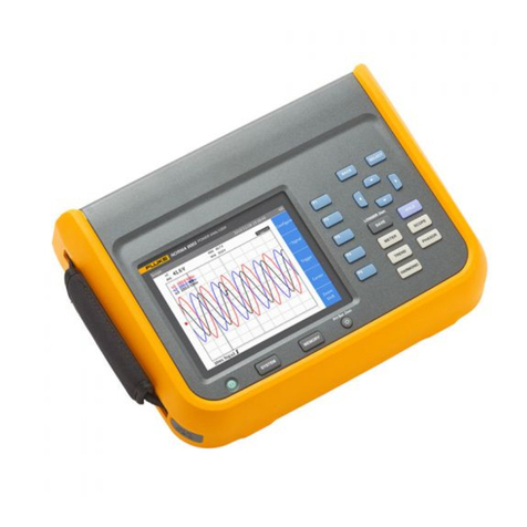
Fluke 1773 Use and care manual

1773/1775/1777
3 Phase Power Quality Analyzer
Calibration Manual
É
4/2022 (English)
©2022 Fluke Corporation. All rights reserved.
Specifications are subject to change without notice.
All product names are trademarks of their respective companies.

LIMITED WARRANTY AND LIMITATION OF LIABILITY
Each Fluke product is warranted to be free from defects in material and workmanship under normal use
and service. The warranty period is 2 years and begins on the date of shipment. Parts, product repairs,
and services are warranted for 90 days. This warranty extends only to the original buyer or end-user
customer of a Fluke authorized reseller, and does not apply to fuses, disposable batteries, or to any
product which, in Fluke's opinion, has been misused, altered, neglected, contaminated, or damaged by
accident or abnormal conditions of operation or handling. Fluke warrants that software will operate
substantially in accordance with its functional specifications for 90 days and that it has been properly
recorded on non-defective media. Fluke does not warrant that software will be error free or operate
without interruption.
Fluke authorized resellers shall extend this warranty on new and unused products to end-user customers
only but have no authority to extend a greater or different warranty on behalf of Fluke. Warranty support is
available only if product is purchased through a Fluke authorized sales outlet or Buyer has paid the
applicable international price. Fluke reserves the right to invoice Buyer for importation costs of repair/
replacement parts when product purchased in one country is submitted for repair in another country.
Fluke's warranty obligation is limited, at Fluke's option, to refund of the purchase price, free of charge
repair, or replacement of a defective product which is returned to a Fluke authorized service center within
the warranty period.
To obtain warranty service, contact your nearest Fluke authorized service center to obtain return
authorization information, then send the product to that service center, with a description of the difficulty,
postage and insurance prepaid (FOB Destination). Fluke assumes no risk for damage in transit. Following
warranty repair, the product will be returned to Buyer, transportation prepaid (FOB Destination). If Fluke
determines that failure was caused by neglect, misuse, contamination, alteration, accident, or abnormal
condition of operation or handling, including overvoltage failures caused by use outside the product’s
specified rating, or normal wear and tear of mechanical components, Fluke will provide an estimate of
repair costs and obtain authorization before commencing the work. Following repair, the product will be
returned to the Buyer transportation prepaid and the Buyer will be billed for the repair and return
transportation charges (FOB Shipping Point).
THIS WARRANTY IS BUYER'S SOLE AND EXCLUSIVE REMEDY AND IS IN LIEU OF ALL OTHER
WARRANTIES, EXPRESS OR IMPLIED, INCLUDING BUT NOT LIMITED TO ANY IMPLIED WARRANTY OF
MERCHANTABILITY OR FITNESS FOR A PARTICULAR PURPOSE. FLUKE SHALL NOT BE LIABLE FOR ANY
SPECIAL, INDIRECT, INCIDENTAL OR CONSEQUENTIAL DAMAGES OR LOSSES, INCLUDING LOSS OF
DATA, ARISING FROM ANY CAUSE OR THEORY.
Since some countries or states do not allow limitation of the term of an implied warranty, or exclusion or
limitation of incidental or consequential damages, the limitations and exclusions of this warranty may not
apply to every buyer. If any provision of this Warranty is held invalid or unenforceable by a court or other
decision-maker of competent jurisdiction, such holding will not affect the validity or enforceability of any
other provision.
11/99
Fluke Corporation
P.O. Box 9090
Everett, WA 98206-9090
U.S.A.
i
Table of Contents
Title Page
Introduction................................................................................................................................... 1
Contact Fluke ............................................................................................................................... 1
Safety Information...................................................................................................................... 1
Specifications .............................................................................................................................. 1
Maintenance ................................................................................................................................. 2
How to Clean........................................................................................................................ 2
Battery Replacement........................................................................................................ 2
Product Disposal................................................................................................................3
Replacement Parts ............................................................................................................ 4
Setup ............................................................................................................................................... 5
Required Equipment ......................................................................................................... 5
Equipment Assembly........................................................................................................ 6
17xx Calibration Cable Assembly ....................................................................... 6
17xx AUX Input Calibration Cable ....................................................................... 7
Verification Box Assembly..................................................................................... 9
System Requirements...................................................................................................... 10
USB Communication......................................................................................................... 10
How to Use the 17xx Calibration Tool........................................................................ 10
Dashboard.................................................................................................................... 11
Verification................................................................................................................... 12
Basic Instrument Setup for all Verifications............................................................. 14
Accuracy Verification Procedure ......................................................................................... 14
Voltage Measurement...................................................................................................... 14
Voltage Transient Measurement.................................................................................. 15
Current Measurement...................................................................................................... 16
AUX Input Check ................................................................................................................ 18
Optional Verification for iFlex or Clamp (Combined Analyzer and
Probe Specifications)................................................................................................................ 19
17xx Auxiliary Input Adapter Verification .......................................................................... 22
Calibration Adjust Procedure................................................................................................. 23
DC-Offset Calibration................................................................................................................ 24

ii
1773/1775/1777
Calibration Manual

1
Introduction
XW Warning
To avoid electric shock or personal injury, do not perform the calibration
verification tests or calibration procedures described in this manual unless you
are qualified to do so. The information provided in this manual is for the use of
qualified personnel only.
This Calibration Manual provides all the information necessary to do basic maintenance, perform
verification, and make calibration adjustments for the 1773/1775/1777 3 Phase Power Quality
Analyzer (Analyzer or Product). For complete operating instructions, refer to the Users Manual at
www.fluke.com.
Contact Fluke
Fluke Corporation operates worldwide. For local contact information, go to our website:
www.fluke.com
To register your product, or to view, print, or download the latest manual or manual
supplement, go to our website.
+1-425-446-5500 fluke-info@fluke.com
Safety Information
General Safety Information is in the printed Safety Information document that ships with the
Product and at www.fluke.com. More specific safety information is listed where applicable.
A Warning identifies hazardous conditions and procedures that are dangerous to the user. A
Caution identifies conditions and procedures that can cause damage to the Product or the
equipment under test.
Specifications
Complete specifications are at www.fluke.com. See the 1773/1775/1777 Product
Specifications.
Fluke Corporation
P.O. Box 9090
Everett WA 98206-9090
U.S.A.
Fluke Europe B.V.
P.O. Box 1186
5602 BD Eindhoven
The Netherlands

1773/1775/1777
Calibration Manual
2
Maintenance
If the Product is used appropriately it does not require special maintenance or repair.
Maintenance work may be executed only by trained and qualified personnel. This work may
only be done at a company-related service center within the guarantee period. See
www.fluke.com for locations and contact information of Fluke Service Centers worldwide.
XW Warning
To prevent possible electrical shock, fire, or personal injury:
Do not operate the Product with the battery door removed or the case open.
Hazardous voltage exposure is possible.
Remove the input signals before you clean the Product.
Use only specified replacement parts.
Have an approved technician repair the Product.
How to Clean
WCaution
To prevent damage, do not use abrasives or solvents on this Product.
If the Product is dirty, wipe it off carefully with a damp cloth (without cleaning agents). Mild
soap may be used.
Battery Replacement
XW Warning
To prevent possible electrical shock, fire, or personal injury:
Do not short the battery terminals together.
Do not disassemble or crush battery cells and battery packs.
Do not put battery cells and battery packs near heat or fire. Do not put in sunlight.
WCaution
Replace the rechargeable battery after 5 years.

3 Phase Power Quality Analyzer
Maintenance
3
The Product has an internal rechargeable Lithium-ion battery.
To replace the battery:
1. Unfasten the screws and remove the battery door. See Figure 1.
Figure 1. Battery
Product Disposal
Dispose of the Product in a professional and environmentally sound manner:
Delete personal data on the Product before disposal.
Remove batteries that are not integrated into the electrical system before disposal and
dispose of batteries separately.
If this Product has an integral battery, put the entire Product in the electrical waste.
BP1770

1773/1775/1777
Calibration Manual
4
Replacement Parts
Table 1 is a list of replacement parts and accessories.To order parts and accessories, see
Contact Fluke.
Table 1. Replacement Parts
Item Description QTY Fluke Part or
Model Number
WiFi-to-USB Adapter 2 4723989
Battery Door 1 4388072
Battery Pac, Li-ion 3.7 V 2500 mAh 1 4146702
USB Cable 1 1671807
Line Cord, country-specific (N. America, Europe,
UK, Australia, Japan, India/S. Africa, Brazil) 1varies
Test Leads 0.8 m blue, 1000 V CAT III 1 set 5016873
Test Leads 2 m, 2x Alligator Clips, blue,
1000 V CAT III 1 set 5020006
Cable Marker 1 set 5046009
Mains Adapter MA-C8 1 4945842
8
4
6
9
5
1
2
3
7

3 Phase Power Quality Analyzer
Setup
5
Setup
Before you start the verification procedures or make calibration adjustments, refer to this
section for the equipment, system, and setup requirements.
Required Equipment
See Table 2 for a list of requirements for the verification tests and calibration adjustment of the
Product.If the specific equipment is not available, use equivalent equipment that has the same
or better performance.
Table 2. Required Equipment
Item Model Comments Used for:
Verification Adjustment
Calibrator 5522A with 8588A
Reference DMM
5730A Calibrator, or
equivalent, if 8588A is
not available.
Digital Multimeter (DMM) 8588A or 8846A
Voltage verification/
calibration and AUX
Adapter verification
Cable Assembly 3PHVL-1730 Voltage Test Lead
3-Phase+N
Test Lead Pomona 6358 For voltage PE
connection
17xx AUX Input
Calibration Cable [1] NA
17xx Calibration Cables:
Voltage-to-Current Input
Cable Assembly[1]
NA
17xx Verification Box[1] NA
USB Cable USB A-to-USB C
Coil
5500A/COIL
Optional: 52120A
with Coils
for iFlex verification
Coil NA 5 turns
Banana-to-Pin Adapter Pomona
Electronics 4690
for AUX Adapter
verification
[1] The 173x/174x calibration cables and verification box are not available from Fluke. See Equipment Assembly
for information on how to make these items. The 17xx calibration equipment is identical with the previous
173x/174x equipment.

1773/1775/1777
Calibration Manual
6
Equipment Assembly
The 17xx calibration cables and verification box are not available from Fluke. If you plan to
calibrate your Product rather than send it to a Fluke Service Center, use the assembly
instructions that follow.
Note
The 17xx calibration cables are identical and the verification box is similar to the
previous 173x/174x calibration equipment.
17xx Calibration Cable Assembly
See Ta ble 3 for instructions on how to make the calibration cables.
WCaution
Cable must be marked with “max. 30 V to earth.” Remove any voltage-, category-,
or current-ratings on safety plugs.
Table 3. 17xx Calibration Cables, Voltage-to-Current-Input
Item Description Part Number/Info QTY
Straight Plug, IP50, 4-Pole ODU: S21M08-P04MJG0-528S 1
Cable Bend Relief ODU: 701-023208965-040 1
Signal-Cable, 2x AWG 22-24, shielded ∅4-5 mm
(Fluke equiv. # 3803634) 1
10
+
2
0
1930
±10
15
±1
4
-
0
1
5 max.
4 min.
Screen
(Pin 4)
N.C.
(Pin 3)
Red Wire
(Pin 1)
Black Wire
(Pin 2)
123
4
5
676

3 Phase Power Quality Analyzer
Setup
7
17xx AUX Input Calibration Cable
See Ta ble 4 and Figure 2 for instructions on how to make the calibration cable.
WCaution
Cable must be marked with “max. 30 V to earth.” Remove any voltage-, category-,
or current-ratings on safety plugs.
Item Description Part Number/Info QTY
Test Lead with 4 mm Safety Plug,
stackable red 1
Test Lead with 4 mm Safety Plug,
stackable black 1
Heat Shrink Tubing, 2:1 ∅=4.8 mm (3/16”); L=35 mm 3
Heat Shrink Tubing, 3:1, adhesive ∅=12 mm (1/2”); L=60 mm 1
Table 4. 17xx AUX Input Calibration Cable
Item Description Part Number/Info QTY
Binder: Series 620 - Male Cordset, 4-pole, 2 m Binder: 79 9241 020 04 1
Test Lead 0.75 mm² with 4 mm Banana Plug,
stackable red 2
Test Lead 0.75 mm² with 4 mm Banana Plug,
stackable black 2
Shrink tube Ø 5-6 mm, black, thin wall, 3:1 L = 30 mm 4
Shrink tube Ø 8-10 mm, transparent, thin wall,
2:1 L = 45 mm 2
Shrink tube Ø 10-12 mm, black, thin wall,
adhesive, 3:1 L = 30135 1
Shrink tube Ø 12-14 mm, black, thin wall, 3:1 L = 110 mm 1
Table 3. 17xx Calibration Cables, Voltage-to-Current-Input (cont.)

1773/1775/1777
Calibration Manual
8
Figure 2. 17xx AUX Input Calibration Cable
155 min.
215
±3
10
Proper shrink tubes for grouping of AUX1 and AUX2 as well as markings for differentiation
(e.g.: label under transparent shrink tube - see above)
AUX1 (
–
)
AUX1 (+)
AUX2 (+)
AUX2 (
–
)
250
±1
Twisted 7 ±1
(4x)
Twisted 7 ±1
(4x)
2
AUX
1
(+)
270
±1
3
AUX
1
(
–
)
290
±1
2
AUX
2
(+)
310
±1
3
AUX
2
(
–
)
1800
±5
20
±1
40
±1
60
±1
80
±1
1
White
Brown
Blue
Black
A
PRE-ASSEMBLY
Solder both ends
(4x)
55
over AUX2
(+) and (-)
over AUX1
(+) and (-)
6
4
4
44
AUX2 (
–
)
AUX2 (+)
AUX1 (+)
AUX1 (
–
)
7
transparent shrink tubes (l=45mm)
over printed labels "AUX 1" & "AUX 2" (w~40mm)
~ 9
DETAIL A
SCALE
2 : 1
Place shrink tube over
solder joint and shrink
(4x)
Connections
Binder-Cable
Test leads
Brown AUX1(+)
Bhite
AUX1(
–
)
Blue
AUX2(+)
Black
AUX2(
–
)
(
–
)

3 Phase Power Quality Analyzer
Setup
9
Verification Box Assembly
This Verification Box provides more accurate voltages than a direct connection to the 5520A. The
5520A uses a divider with a 50 Ωoutput impedance when sourcing <330 mV. Due to variations in
the Analyzer input impedance, the actual applied voltage is less than the programmed voltage.
Using an external divider where the parallel resistance is ~30 Ωallows calculation of the applied
voltage with confidence that the Analyzer input loading will not significantly impact the applied
voltage.
Fluke recommends using a verification box that has a divider with 30 Ωacross the Analyzer input
and 10 kΩin series with high side of the input. See Table 5 for instructions on how to make the
verification box.
Table 5. 17xx Verification Box
Item Description Part Number/Info Fluke
Part Number QTY
Plastic Box: 2.69 in L x 1.82 in W Pomona: 3850-0 1924576 1
Binding Post, Black Pomona: 4243-0 1633063 2
Resistor, Metal Foil 10 kΩ,
±0.1 %, 0.6 W, ±4.5 PPM Red Plug/Red Socket 2114858 1
Resistor, 30 Ω, 1 W, 1 % 20 PPM Red Socket/Black Socket +
Bridge Black Plug/Socket 1757740 1
2
3
21
Contacts Pretinned
Contacts
Pretinned
Red
Plug
Red
Socket
Black
Socket
Black
Plug
Soldered
Soldered
Soldered
Soldered
10 k
30
Ω
Red
Black Black
Red
.375
(9.53)
Panel Cutout
.750
(19.05)
V
in
V
out

1773/1775/1777
Calibration Manual
10
System Requirements
The system requirements for this verification procedure are:
Windows 10 or Windows 11 32/64-bit (earlier Windows versions below 10 are not tested)
Monitor, 1280 x 1024 (@4:3) or 1440 x 900 (@16:10), wide-screen (16:10) at higher
resolution recommended
USB 2.0 port
RS232 port or USB-to-RS232 converter to control the calibrator (optional)
Microsoft Excel 2010 32/64-bit software or higher (versions below 2010 are not tested)
Fluke Energy Analyze software V3.8 or higher
USB Communication
The verification and adjustment require remote commands to query measurement data and
write commands to set configurations that are not available on the instrument UI. To
communicate between the PC and the instrument, either a USB 2.0 type A to USB-C or USB-C
to USB-C cable can be used. The device driver is included with the Windows operating system.
How to Use the 17xx Calibration Tool
The application, Fluke17xx-CalibrationTool_Vx.x is available at www.fluke.com and
communicates with the instrument using remote commands through the USB ports. The
application also supports the control of the Fluke Calibrators for automated procedures.
The application (Calibration Tool) contains sheets for various tasks:
Dashboard – Live measurements and set current input range/mode
Verification – Procedures to perform the verification
Adjustment – Procedures to perform the adjustment
Setup – Configuration of, for example, the COM ports and resistor values of the voltage
divider

3 Phase Power Quality Analyzer
Setup
11
Dashboard
The Dashboard sheet provides all measurement readings at a glance that are required for
manual calibration. See Ta b l e 6 .
Table 6. Dashboard
Item Description
Refresh: One-time live data update.
Continuous: Start live data read-out. The readings are refreshed every few
seconds. Use the same button to stop live updates. During the live updates
other tabs are not accessible.
Phase to Earth: Switch voltage measurement between Phase-to-Neutral
and Phase-to-Earth.
Type: Select the type of the current accessory. The options are Auto,
Clamp, iFlex, and DC-Clamp. The default is Auto.
Range: Select the range of the current channels. The options are Auto,
High, and Low. The default is Auto.
1 2
3
4 5

1773/1775/1777
Calibration Manual
12
Verification
The Verification and Adjustment sheets are the built-in procedures. See Tabl e 7 .
Table 7. Calibration
Item Description
Verification items: For a complete instrument verification all of these items
must be verified in successive tests: Voltage, Voltage Transient, Current,
and AUX. A specific order is not required. Completed items are shown with
a check mark.
Result: Status of the verification items. After performing the verification,
the result of each item shall be PASS. FAIL indicates a deviation outside the
tolerance limits.
Start: Start of the verification for the selected item.
Status: Log of the verification process. This information is also stored in a
log file.
1
2
3
4

3 Phase Power Quality Analyzer
Setup
13
Tabl e 8. Setu p
Item Description
17xx COM Port: The 17xx_CalibrationTool automatically searches for the COM port
of the connected device and the found port is displayed here.
Calibrator Control Setup: When the calibrator is connected to the PC using a
RS232 cable select Automatic to control the calibrator. Use the drop-down list box to
configure the COM port. Otherwise select Manual.
Multimeter Control Setup: When the DMM is connected to the PC with a GPIB
interface, select Automatic to control the DMM and read the measurement values.
Use the drop-down list box to configure the GPIB port. Otherwise, select Manual.
Voltage Divider Setup: Configure the resistor values, R1 and R2, of the voltage
divider for current verification. Store the Excel workbook to keep the applied values
for future use.
File: This is the file with the verification parameters. Usually there is no need to
change this definition.
Supported Calibrators:
Fluke 5522A with reference DMM 8588A. 5730A for voltage verification/calibration only.
Calibrator settings:
Baud rate: 9600
Data bits: 8 Stop bit: 1
Parity: None
Stall: XON/XOFF
EOL: CR/LF
DMM settings:
Remote interface: GPIB or USB (on 8558A)
8558A only:
Emulation: 8508A
1
2
3
4
5

1773/1775/1777
Calibration Manual
14
Basic Instrument Setup for all Verifications
The Fluke17xx-CalibrationTool_Vx.x has built-in procedures to verify and adjust the Analyzer.
The Verification of uses an external divider. This divider, (see Verification Box Assembly)
provides more accurate voltages than a direct connection to the 5520A. The 5520A uses a
divider with a 50 Ωoutput impedance when sourcing <330 mV. Due to variations in the Analyzer
input impedance, the actual applied voltage is less than the programmed voltage. Using an
external divider where the parallel resistance is ~30 Ωallows calculation of the applied voltage
with confidence that the Analyzer input loading will not significantly impact the applied voltage.
The Calibration Tool calculates the voltage that should be applied based on the values entered
in the setup screen:
1. Apply power to the Analyzer using the power supply and line cord.
2. Turn on the Analyzer.
3. Connect the Analyzer USB to the PC.
Accuracy Verification Procedure
The procedure verifies the Analyzer accuracy at ambient temperature 23 °C ±5 °C (intrinsic
error). Allow at least one hour for the Analyzer to warm up.
A complete accuracy verification of the 177x consists of:
Voltage Measurement
Voltage Transient Measurement (1775 and 1777 only)
Current Measurement
AUX Measurement
Optional iFlex, Current Clamp, and 17xx Auxiliary Input Adapter Verification
Voltage Measurement
To m e a s u re v o l t a g e :
1. Select the setup. See Basic Instrument Setup for all Verifications.
2. Make sure the instrument is on battery power with ≥50 % charge.
3. Connect the 3PHVL-1730 "N" lead and the single test lead Earth to the calibrator
NORMAL LO.
4. Use the 55x2A or 5730A calibrator to:
a. Connect the calibrator NORMAL V output to the 3PHVL-1730 L1+L2+L3 leads.
b. Connect the calibrator NORMAL V output to the V input of the reference DMM.
c. Sequentially set the calibrator to the voltages in Table 9 and check that the Analyzer
reading is between the limits.
Note
Use the DMM readings as reference with the 55x2A calibrator.

3 Phase Power Quality Analyzer
Accuracy Verification Procedure
15
5. Do this for all ranges in Table 9:
a. Set the calibrator to supply a 57.0 Hz sine wave for all voltages.
b. Wait until each reading has stabilized.
The Calibration Tool is the first choice for readings because the resolution is higher than
the instrument UI. If this is not available, select PQ Meter from Home menu to see the
voltage readings.
6. When you are done, set the calibrator to Standby.
Voltage Transient Measurement
This verification is required on the 1775 and 1777 models only.
To measure transient voltage:
1. Select the setup. See Basic Instrument Setup for all Verifications.
2. Make sure the Analyzer is on battery power with ≥50 % charge.
3. Connect the single test lead Earth to the calibrator NORMAL LO.
4. Use the 552xA or 57x0A calibrator to:
a. Connect the calibrator NORMAL V output to the 3PHVL-1730 L1+L2+L3+N leads.
b. Connect the calibrator NORMAL V output to the V input of the reference DMM.
Table 9. Voltage Verification
Declared
Input
Voltage
Udin[1]
Range Calibrator Voltage
57 Hz sine wave
Minimum Reading
-0.1 % of Udin
Maximum Reading
+0.1 % of Udin
for 10 % to 150 % of supported Udin:
± (0.1 % of Udin), otherwise 0.1 % of range
120 V
1000 V 12 V 11.88 V 12.12 V
1000 V 120 V 119.88 V 120.12 V
1000 V 180 V 179.88 V 180.12 V
230 V
1000 V 23 V 22.77 V 23.23 V
1000 V 230 V 229.77 V 230.23 V
1000 V 345 V 344.77 V 345.23 V
480 V
1000 V 48 V 47.52 V 48.48 V
1000 V 480 V 479.52 V 480.48 V
1000 V 720 V 719.52 V 720.48 V
690 V 1000 V 1000 V[2] 999.31 V 1000.69 V
[1] In the power quality standard IEC 61000-4-30, the declared input voltage Udin determines the accuracy
requirements of voltages from 10 % to 150 % of Udin. For measurements in low voltage mains supplies, Udin
is identical to the nominal supply voltage, for example 120 V or 230 V.
[2] The test voltage is limited by the maximum output voltage of the calibrator. According to IEC 61000-4-30 the
150 % test voltage is 1035 V.

1773/1775/1777
Calibration Manual
16
c. Sequentially set the calibrator to the voltages and frequencies in Tab l e 10 and check
that the Analyzer reading is between the limits.
Note
Use the DMM readings as reference with the 552xA calibrator.
5. Do this for all ranges in Table 10:
a. Set the calibrator to supply a sine wave for all voltages.
b. Wait until each reading has stabilized.
The spreadsheet is the first choice for readings. Readings will have more resolution from
the spreadsheet.
Use the Calibration Tool for the RMS readings. Note that the instrument UI does not provide
the voltage transient RMS values.
If the Calibration Tool is not available, you can do manual readings:
1. Start a Logging session
2. Apply the voltages from Ta b le 10.
Be sure to wait at least 30 seconds between the test steps.
3. Download the measurement to Energy Analyze Plus software.
4. Go to PQ+ Study > Events.
5. Select the transient events and use the cursors on the transient waveform recordings to
identify the peak-to-peak voltage of the sine wave.
6. Calculate the RMS value by dividing the peak-to-peak reading by 2.8284.
7. When you are done, set the calibrator to Standby.
Current Measurement
Fluke recommends using a divider with 30 Ωacross the Analyzer input and 10 kΩin series with
high side of the input:
Fluke PN 2114858 (10 kΩ)
Fluke PN 1757740 (30 Ω) – see Table 5 for the recommended assembly of this divider. Best
practice is to measure the resistor values at time of use.
Table 10. Transient Voltage Calibration
Calibration Output Range Minimum Reading Maximum Reading
Voltage Frequency
1000 V 200 Hz ±8 kV 930 V 1070 V
600 V 10 kHz ±8 kV 550 V 650 V
200 V 100 kHz ±8 kV 170 V 230 V
Other manuals for 1773
1
This manual suits for next models
2
Table of contents
Other Fluke Measuring Instrument manuals

Fluke
Fluke 317 User manual

Fluke
Fluke 9142 User manual

Fluke
Fluke Series II User manual

Fluke
Fluke IRR1-SOL User manual

Fluke
Fluke VIBGUARD IIoT Guide

Fluke
Fluke etherscope II User manual

Fluke
Fluke i430-Flexi-TF User manual

Fluke
Fluke 373 Instruction manual

Fluke
Fluke 345 Instruction manual

Fluke
Fluke 3140R User manual

Fluke
Fluke 323 User manual

Fluke
Fluke 1520 User manual

Fluke
Fluke 945 User manual

Fluke
Fluke i5s-PR 1750 5A User manual

Fluke
Fluke BT520 Configuration guide

Fluke
Fluke LS-1310 Manual

Fluke
Fluke 30 Operating and installation instructions

Fluke
Fluke 712 User manual

Fluke
Fluke 80K-40 User manual

Fluke
Fluke 700G01 User manual