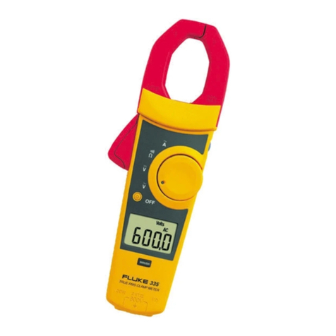
Fluke 902 User manual

®
PN 2547887
May 2006 Rev. 1, 3/07
© 2006-2007 Fluke Corporation. All rights reserved. Printed in China.
All product names are trademarks of their respective companies.
902
HVAC Clamp Meter
Users Manual

LIMITED WARRANTY AND LIMITATION OF LIABILITY
This Fluke product will be free from defects in material and
workmanship for three years from the date of purchase.
This warranty does not cover fuses, disposable batteries, or
damage from accident, neglect, misuse, alteration, con-
tamination, or abnormal conditions of operation or handling.
Resellers are not authorized to extend any other warranty
on Fluke’s behalf. To obtain service during the warranty
period, contact your nearest Fluke authorized service cen-
ter to obtain return authorization information, then send the
product to that Service Center with a description of the
problem.
THIS WARRANTY IS YOUR ONLY REMEDY. NO OTHER
WARRANTIES, SUCH AS FITNESS FOR A PARTICULAR
PURPOSE, ARE EXPRESSED OR IMPLIED. FLUKE IS
NOT LIABLE FOR ANY SPECIAL, INDIRECT, INCIDEN-
TAL OR CONSEQUENTIAL DAMAGES OR LOSSES,
ARISING FROM ANY CAUSE OR THEORY. Since some
states or countries do not allow the exclusion or limitation of
an implied warranty or of incidental or consequential dam-
ages, this limitation of liability may not apply to you.
Fluke Corporation
P.O. Box 9090
Everett, WA 98206-9090
U.S.A.
Fluke Europe B.V.
P.O. Box 1186
5602 BD Eindhoven
The Netherlands
11/99

i
Table of Contents
Title Page
Introduction....................................................... 1
Contacting Fluke .............................................. 2
Safety Information ............................................ 3
Symbols ........................................................... 5
Getting Acquainted with the Meter ................... 6
Using the Meter................................................ 10
AC and DC Voltage Measurement................. 10
Resistance and Continuity ............................. 11
Microamps µA Measurement ......................... 12
Temperature .................................................. 13
Capacitance................................................... 16
AC Current Measurement .............................. 16
Backlight ........................................................ 18
MIN MAX Recording Mode ............................ 18
Display HOLD ................................................ 19
Auto Off.......................................................... 19
Maintenance..................................................... 20
Cleaning the Meter......................................... 20
Battery Replacement ..................................... 21
Specifications ................................................... 23
Electrical Specifications ................................. 23
General Specifications ................................... 24

902
Users Manual
ii

iii
List of Tables
Table Title Page
1. 902 HVAC Clamp Meter Features.................... 7
2. Display Features .............................................. 9
List of Figures
Figure Title Page
1. 902 HVAC Clamp Meter Features.................... 6
2. Display Features .............................................. 8
3. Testing a Flame Rod ........................................ 13
4. Temperature Measurement.............................. 15
5. Proper AC Current Measurement..................... 17
6. Battery Replacement........................................ 22

902
Users Manual
iv

1
902
Introduction
The Fluke 902 is a hand-held battery-operated HVAC
Clamp Meter (“the Meter”) that measures:
•AC current
•DC current (up to 200 µA for flame rod testing)
•AC and DC voltages
•Capacitance
•Resistance
•Continuity
•Temperature in both Celsius (°C) and Fahrenheit (°F)
The Meter comes with:
•Two AA alkaline batteries (installed)
•Users Manual
•Soft carrying case
•TL75 Test Leads (one pair)
•80BK Integrated DMM Temperature Probe

902
Users Manual
2
Contacting Fluke
To contact Fluke, call one of the following telephone
numbers:
USA: 1-888-99-FLUKE (1-888-993-5853)
Canada: 1-800-36-FLUKE (1-800-363-5853)
Europe: +31 402-675-200
Japan: +81-3-3434-0181
Singapore: +65-738-5655
Anywhere in the world: +1-425-446-5500
Or visit Fluke’s Web site at: www.fluke.com.
Register the Meter at: http://register.fluke.com

HVAC Clamp Meter
Contacting Fluke
3
Safety Information
A “XW Warning” statement defines hazardous conditions
and actions that could cause bodily harm or death.
A “W Caution” statement identifies conditions and actions
that could damage the Meter or the equipment under test.
XWRead First: Safety Information
To ensure safe operation and service of the
Meter, follow these instructions:
•Read the Users Manual before use and
follow all safety instructions.
•Use the Meter only as specified in the
Users Manual; otherwise, the Meter's
safety features may be impaired.
•Avoid working alone so assistance can be
rendered.
•Never use the Meter on a circuit with
voltages higher than 600 V or a frequency
higher than 400 Hz fundamental. The Meter
may be damaged.
•Never measure ac current while the test
leads are inserted into the input jacks.
•Do not use the Meter or test leads if they
look damaged.
•Use extreme caution when working around
bare conductors or bus bars. Contact with
the conductor could result in electric
shock.

902
Users Manual
4
•Use caution when working with voltages
above 60 V dc or 30 V ac rms or 42 V ac
peak. Such voltages pose a shock hazard.
•Clean the case with a damp cloth and mild
detergent only. Do not use abrasives or
solvents.
•To avoid false readings that can lead to
electrical shock and injury, replace the
batteries as soon as the low battery
indicator (B) appears. As the Meter gets
to the point where the low batteries affect
the readings, the Meter locks and no
measurements can be made until the
batteries are changed.
•Do not hold the Meter anywhere beyond
the tactile barrier, see Figure 1.
•Adhere to local and national safety codes.
Individual protective equipment must be
used to prevent shock and arc blast injury
where hazardous live conductors are
exposed.

HVAC Clamp Meter
Symbols
5
Symbols
The following symbols are found on the Meter or in this
manual.
,May be used on hazardous live conductors
WRisk of danger. Important information. See Users
Manual.
X Hazardous voltage. Risk of electric shock.
TDouble insulation
B Battery
)Complies with Canadian and US Standards
PConforms to relevant European Union directives
JEarth ground
FDC (Direct Current)
BAC (Alternating Current)
~Do not dispose of this product as unsorted municipal
waste. Contact Fluke or a qualified recycler for
disposal.
;
N10140 Conforms to relevant Australian standards
sInspected and licensed by TÜV Product Services

902
Users Manual
6
Getting Acquainted with the Meter
Refer to Figures 1 and 2 and Tables 1 and 2 to become
more acquainted with the Meter’s features.
COM
600V
CAT V
µ
A
efu0001.eps
Figure 1. 902 HVAC Clamp Meter Features

HVAC Clamp Meter
Getting Acquainted with the Meter
7
Table 1. 902 HVAC Clamp Meter Features
Number Description
A Backlight Button
B Jaw Release
C Tactile Barrier
D Jaws
E Hold Button
F Rotary Switch:
V DC and AC voltage
P Resistance and continuity
G DC microamps
F Degrees Fahrenheit / degrees Celsius
L Capacitance
K AC current
G LCD
H Min Max Button
I AC/DC, °F/°C Button
J Input Terminals

902
Users Manual
8
A
B
CDEF
G
efu0006.eps
Figure 2. Display Features

HVAC Clamp Meter
Getting Acquainted with the Meter
9
Table 2. Display Features
Number Indication
A
Battery indicator -The batteries are low and need to
be changed. XWWarning: To avoid false
readings, which could lead to possible
electric shock or personal injury, replace
the batteries as soon as the battery
indicator appears.
B Indicates the presence of high voltage
C Indicators for minimum and maximum recording
mode
D Display Hold is active
E Volts
F Amps
G
°F - Degrees Fahrenheit
°C- Degrees Celsius
e- Ohms
M- Microamps
N- Microfarads
DC - Direct Current
AC - Alternating Current

902
Users Manual
10
Using the Meter
AC and DC Voltage Measurement
To measure AC or DC voltage:
1. Insert the test leads into the Meter.
2. Turn the rotary switch to V.
3. Press Ato choose AC or DC voltage. The display
reflects the chosen voltage mode.
4. Use the test leads to take the measurement. The Meter
reading appears on the display.
Note
When a measured voltage is above 30 V,
Zappears on the display. When the voltage drops
below 30 V, Zdisappears.

HVAC Clamp Meter
Using the Meter
11
Resistance and Continuity
To measure resistance or continuity:
XW Warning
To avoid false readings that can lead to
electrical shock and injury, de-energize the
circuit before taking the measurement.
1. Insert the test leads into the Meter.
2. Turn the rotary switch to P.
3. Take the measurement. The resistance reading
appears on the display.
•If the resistance is shorted, the Meter beeps and
shows a reading < 30 Ω.
•If the resistance is open or exceeds the Meter’s
range, the display reads OL.

902
Users Manual
12
Microamps
µ
A Measurement
The µA dc (G) function on the Meter is primarily for HVAC
flame rod testing. To test a heating system flame rod (refer
to Figure 3):
1. Turn the heating unit off and locate the wire between
the gas-burner controller and the flame rod.
2. Break this connection.
3. Turn the rotary switch on the Meter to G.
4. Using alligator clips, connect test leads between the
flame sensor probe and control-module wire.
5. Turn heating unit on and check the reading on the
Meter.
6. Refer to the heating unit documentation for what the
desired reading should be.

HVAC Clamp Meter
Using the Meter
13
Burner
efu0004.eps
Figure 3. Testing a Flame Rod
Temperature
The Meter measures temperature in either Celsius (°C) or
Fahrenheit (°F).
To measure temperature (refer to Figure 4):

902
Users Manual
14
1. Connect the 80BK Integrated DMM Temperature
Probe to the input jacks noting correct polarity of the
probe.
2. Turn the rotary switch to F.
3. Press Ato select °C or °F. The display reflects the
chosen temperature mode.
4. Position the probe to take the measurement. The
reading appears on the display.
Note
To meet stated accuracy, the 80BK and Meter
must be at the same temperature.
XW Warning
To avoid possible electric shock DO NOT apply
the probe tip to any conductor that is greater
than 30 V ac, 42 V peak or 60 V dc to earth.
Other manuals for 902
2
Table of contents
Other Fluke Measuring Instrument manuals
Fluke
Fluke 368 Use and care manual

Fluke
Fluke 902 User manual

Fluke
Fluke i6000s Flex Series User manual

Fluke
Fluke WaveRunner User manual

Fluke
Fluke i30s User manual

Fluke
Fluke 80K-40 User manual

Fluke
Fluke 419D User manual

Fluke
Fluke SigmaPace 1000 User manual

Fluke
Fluke DewK User manual

Fluke
Fluke 726 Configuration guide
Popular Measuring Instrument manuals by other brands

ATAGO
ATAGO PAL-Fish Fillets instruction manual

BOVIAR
BOVIAR T-TEST K12 user manual

P3 International
P3 International Kill A Watt user manual

ZURN
ZURN ZEMS6000AV Installation, operation, maintenance and parts manual

Phynix
Phynix DC-2000C instruction manual

LaserLiner
LaserLiner CompactLine-Laser G360 manual