English
Page 2
OPERATION
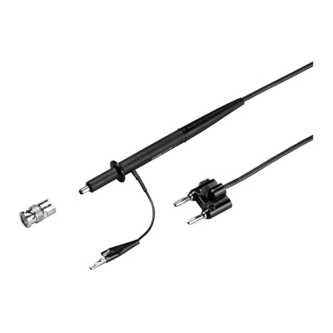
Use the following procedure to operate the 85RF Probe.
1. Connect the probe output to a compatible voltmeter
using a suitable shunt if required. Probe output low must be
connected to voltmeter low.
2. Select an appropriate voltage range (1V dc reading per
1V rms probe input).
3. Connect the input low (clip lead or tip shield) to earth
ground. WARNING
INPUT LOW IS INTENDED TO BE CONNECTED TO EARTH
GROUND. TO AVIOD ELECTRICAL SHOCK, INPUT LOW (CLIP
LEAD OR TIP SHIELD) MUST BE CONNECTED TO POTENTIALS
OF LESS THAN 30V AC, 42V PEAK, OR 60V DC.
a. Measurements at frequencies below 100 MHz can be
made by grounding the 4-inch clip lead supplied with the
probe, then touching the probe tip to the circuit under test.
b. Measurements above 100 MHz must be made using
minimum cable lengths to terminated 50-ohm system. One
inch of unterminated coaxial cable (such as a BNC adapter
and 50-ohm termination) is sufficiently short for up to 300
MHz.
c. Measurements above 300 MHz must have the probe tip
and tip shield (input high and low) touching the circuit under
test to realize the rated accuracy of the probe. Lead lengths
even less than 1 inch may cause significant errors.
CAUTION
To avoid probe damage, the dc component of the input signal
must not exceed 200 volts, including transients. 30V ac rms and
200V dc are the maximum inputs to the probe. This allows
measurements of an ac signal riding on a dc voltage of up to
200V. The input capacitor charges to the peak value of ac plus
dc. If the dc level is then changed by more than 200V, the
resulting transient may damage the probe. The chance of
damage can be minimized by discharging the input capacitor at
the end of each measurement. This is done by momentarily
touching the probe tip to the ground clip.
THEORY OF OPERATION
Circuitry within the 85RF consists of a capacitor-coupled
rectifier circuit which responds to the peak value of the input
waveform. The output is a positive dc voltage which is
calibrated to be equivalent to the rms value of a sine wave
input. See Figure 1. R1, R2, R3. and CR2 form a divider to
properly scale the dc output when the probe output is
connected to a dc voltmeter having a 10-megohm input
resistance. Diode CR2 compensates for the low level
linearity error caused by diode CR1.
MAINTENANCE
Performance Test/Calibration
The performance test is designed to ensure that the 85RF is
operating within specifications. Use the procedure as an
acceptance test and/or calibration procedure (the probe has
one adjustment). The recommended calibration interval is
one year.
1. Set up the equipment as shown in Figure 2. Using the
leveled sine function of the scope output, set the AC
www. .com information@itm.com1.800.561.8187
