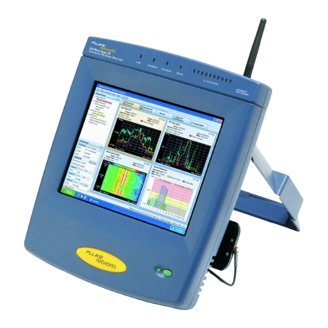
Fluke OptiView T1/E1 User manual

OptiView™
T1/E1 and DS3/E3 WAN Analyzers
Getting Started Guide
PN 2140599
April 2004
© 2004 Fluke Corporation, All rights reserved. Printed in USA
All product names are trademarks of their respective companies.

LIMITED WARRANTY & LIMITATION OF LIABILITY
Each Fluke Networks product is warranted to be free from defects in material and
workmanship under normal use and service. The warranty period is one year and begins on the
date of purchase. Parts, accessories, product repairs and services are warranted for 90 days.
This warranty extends only to the original buyer or end-user customer of a Fluke Networks
authorized reseller, and does not apply to disposable batteries, cable connector tabs, cable
insulation-displacement connectors, or to any product which, in Fluke Networks' opinion, has
been misused, altered, neglected, contaminated, or damaged by accident or abnormal
conditions of operation or handling. Fluke Networks warrants that software will operate
substantially in accordance with its functional specifications for 90 days and that it has been
properly recorded on non-defective media. Fluke Networks does not warrant that software will
be error free or operate without interruption.
Fluke Networks authorized resellers shall extend this warranty on new and unused products to
end-user customers only but have no authority to extend a greater or different warranty on
behalf of Fluke Networks. Warranty support is available only if product is purchased through a
Fluke Networks authorized sales outlet or Buyer has paid the applicable international price.
Fluke Networks reserves the right to invoice Buyer for importation costs of repair/replacement
parts when product purchased in one country is submitted for repair in another country.
Fluke Networks' warranty obligation is limited, at Fluke Networks' option, to refund of the
purchase price, free of charge repair, or replacement of a defective product which is returned
to a Fluke Networks authorized service center within the warranty period.
To obtain warranty service, contact your nearest Fluke Networks authorized service center to
obtain return authorization information, then send the product to that service center, with a
description of the difficulty, postage and insurance prepaid (FOB Destination). Fluke Networks
assumes no risk for damage in transit. Following warranty repair, the product will be returned
to Buyer, transportation prepaid (FOB Destination). If Fluke Networks determines that failure
was caused by neglect, misuse, contamination, alteration, accident or abnormal condition of
operation or handling, or normal wear and tear of mechanical components, Fluke Networks
will provide an estimate of repair costs and obtain authorization before commencing the work.
Following repair, the product will be returned to the Buyer transportation prepaid and the
Buyer will be billed for the repair and return transportation charges (FOB Shipping Point).
THIS WARRANTY IS BUYER'S SOLE AND EXCLUSIVE REMEDY AND IS IN LIEU OF ALL OTHER
WARRANTIES, EXPRESS OR IMPLIED, INCLUDING BUT NOT LIMITED TO ANY IMPLIED
WARRANTY OF MERCHANTABILITY OR FITNESS FOR A PARTICULAR PURPOSE. FLUKE
NETWORKS SHALL NOT BE LIABLE FOR ANY SPECIAL, INDIRECT, INCIDENTAL OR
CONSEQUENTIAL DAMAGES OR LOSSES, INCLUDING LOSS OF DATA, ARISING FROM ANY CAUSE
OR THEORY.
Since some countries or states do not allow limitation of the term of an implied warranty, or
exclusion or limitation of incidental or consequential damages, the limitations and exclusions of
this warranty may not apply to every buyer. If any provision of this Warranty is held invalid or
unenforceable by a court or other decision-maker of competent jurisdiction, such holding will
not affect the validity or enforceability of any other provision.
Fluke Networks, Inc.
PO Box 777
Everett, WA 98206-0777
USA
6-01

i
Table of Contents
Title Page
Using This Guide................................................................................ 1
Introduction ...................................................................................... 2
Overview of Features .................................................................. 2
Available Models......................................................................... 3
Care and Maintenance................................................................ 4
Safety Information ...................................................................... 5
Service and Adjustment .............................................................. 6
Contacting Fluke Networks......................................................... 7
Standard Accessories ................................................................... 8
Registering the OptiView WAN Analyzer................................... 10
Front Panel .................................................................................. 11
MANAGEMENT Port ................................................................ 12
LEDs.......................................................................................... 12
WAN Interfaces........................................................................ 13
Back Panel.................................................................................... 13
Turning on the Analyzer................................................................... 14
Setting Up the Analyzer.................................................................... 15
Statically Assigning the MANAGEMENT Port’s IP Address......... 16
Connecting the Analyzer............................................................. 18
Installing a Tap on the WAN Link ........................................... 18
Connecting the Analyzer’s Ethernet MANAGEMENT Port
to the LAN................................................................................ 25
Connecting the PC to the Network......................................... 25
The Remote User Interface ............................................................... 27
System Requirements .................................................................. 27
Installing the Remote User Interface.......................................... 28
Starting the Remote User Interface............................................ 28
The OptiView Browser ................................................................ 29
The Online Help........................................................................... 33
Finding a Help Topic................................................................ 33

OptiView
Getting Started Guide
ii
Navigating the Help................................................................ 34
Opening and Closing the Left Pane........................................ 34
Printing Help Topics ................................................................ 34
The Front Page ............................................................................ 35
Front Page Main Buttons ........................................................ 37
Additional Front Page Buttons ............................................... 41
Configuring the Analyzer ................................................................. 43
Changing the Management Port Configuration........................ 44
Specifying the WAN Interface and Physical Layer Parameters .. 45
Setting Password Controls .......................................................... 46
Protecting the Privacy of Your Data........................................... 47
Updating the Software..................................................................... 49
Step 1: Update the Remote User Interface Software on the PC 49
Step 2: Update the Analyzer’s Firmware.................................... 50
Optional Accessories ......................................................................... 51
OptiView WAN Analyzer Specifications........................................... 54

1
OptiView T1/E1 and DS3/E3
WAN Analyzers
Using This Guide
This Getting Started Guide is supplied with the OptiView™ T1/E1 WAN
Analyzer and the OptiView DS3/E3 WAN Analyzer to help you get
started learning to use your new analyzer quickly and more efficiently.
The guide introduces you to the key features and operation of these
analyzers and describes the steps to follow to set up and operate them
remotely from a PC.
This guide provides a quick overview of the OptiView T1/E1 and DS3/E3
WAN Analyzers’ main features and functions. After you install the
remote control software from the OptiView Resource CD, you will find
the online Help system the best source for answering questions you
may have about using your analyzer to monitor the performance of
WAN links.

OptiView
Getting Started Guide
2
Introduction
The OptiView T1/E1 and DS3/E3 WAN Analyzers are distributed Wide
Area Network analyzers that can be used to monitor the performance
of T1/E1 and DS3/E3 networks, respectively.
Both WAN analyzers are automated tools that provide meaningful
information about your WAN immediately—with virtually no need for
configuration. Measured parameters are analyzed and important
information is "rolled up" into a comprehensive "front-page" view,
giving you the ability to remotely view the health status of any of your
WAN links from the physical layer to the application layer. You can
even perform packet captures when necessary.
Overview of Features
The OptiView T1/E1 and DS3/E3 WAN Analyzers are designed for
testing Frame Relay or Point-to-Point networks. The T1/E1 model
features full-duplex interfaces for T1, E1, and Serial WAN link access
points while the DS3/E3 WAN Analyzer features full-duplex interfaces
for DS3, E3, and HSSI WAN link access points.
Both models offer the following features:
•Allow non-intrusive monitoring of full-duplex links
•Provide multi-user, simultaneous remote access through a
10/100MB Ethernet MANAGEMENT port
•SNMP-enabled, providing MIB II, RMON, and RMON2 traffic analysis
•Perform passive and active network discovery with address-to-name
resolution

OptiView T1/E1 and DS3/E3 WAN Analyzers
Introduction
3
•Track latency and availability of key network devices
•Provide bandwidth utilization statistics, including top applications,
conversations, and protocols
•Provide instant HTML reports for all seven layers of statistics and
problem tracking
•Feature a dedicated packet capture engine with protocol decoding
available through Fluke Networks Protocol Expert software or
other third-party packet decoder applications.
Available Models
The OptiView T1/E1 and DS3/E3 WAN Analyzers are available in the
following models:
•OptiView T1/E1 WAN Analyzer: WAN link analyzer for Frame Relay
or Point-to-Point networks. Features full-duplex interfaces for T1,
E1, and Serial WAN link access points.
•OptiView DS3/E3 WAN Analyzer: WAN link analyzer for Frame
Relay or Point-to-Point networks. Features full-duplex interfaces for
DS3, E3, and HSSI WAN link access points.
•OptiView T1/E1 WAN Distributed Vision Suite: a bundle that
includes the OPV-WAN/T1E1, OptiView Console, and OptiView
Protocol Expert.
•OptiView DS3/E3 WAN Distributed Suite: a bundle that includes
OPV-WAN/DS3E3, OptiView Console, and OptiView Protocol Expert.
Contact your nearest Fluke Networks Distributor or Service Center for
purchasing information (see “Contacting Fluke Networks”).

OptiView
Getting Started Guide
4
Care and Maintenance
The OptiView WAN Analyzer is designed to be maintenance free. Treat
it with care to ensure the best performance. The suggestions below
will help you fulfill the obligations of the warranty and enjoy your
analyzer for many years.
•Avoid rough handling
Although the analyzer can absorb shock and vibration, avoid
dropping it. If you must ship the analyzer, use the original
packaging or the ruggedized transit case (see “Optional
Accessories”).
•Clean carefully
To clean the analyzer, use a soft, slightly damp cloth. To remove
any stains, use a mild soap. Never use detergents, solvents, or
abrasive cleaners on the analyzer.
•Provide adequate ventilation
Always place the analyzer in an area where there is sufficient space
in front and behind the unit to provide adequate ventilation.

OptiView T1/E1 and DS3/E3 WAN Analyzers
Introduction
5
Safety Information
To avoid possible electric shock or personal injury, the following
general safety precautions must be observed during all phases of
operation, service, or repair of the analyzer. Failure to comply with
these precautions or with specific warnings in this guide violates the
safety standards of design, manufacture, and intended use of the
analyzer. Fluke Networks assumes no liability for the customer’s failure
to comply with these requirements.
WWarnings
If this product is used in a manner not specified by
the manufacturer, the protections provided by the
product may be impaired.
The chassis is expected to be connected to earth
ground through the power cord as required for a
CLASS 1 instrument. Verify that the instrument
chassis is connected to earth to ground.
Insure that the power cord remains accessible for
disconnection from the power source.
Do not use the analyzer if it is damaged. Before
using, inspect the case. Look for cracked or missing
case parts. Pay particular attention to the insulation
surrounding the connectors.
Do not operate the analyzer around explosive gas,
vapor, or dust.
When servicing the analyzer, use specified
replacement parts only.
Do not connect a telephone line to the analyzer.
Provide adequate ventilation in front of and behind
the analyzer.

OptiView
Getting Started Guide
6
Table 1 describes the international electrical symbols used on the
analyzer or in the accompanying documentation.
Table 1. International Electrical Symbols
Symbol Meaning
WWarning or Caution: Risk of damage or destruction to equipment or software.
jDo not connect the analyzer’s network interfaces to public telephone systems.
CAT II OVERVOLTAGE (Installation) CATEGORY II, Pollution Degree 2 per IEC1010-1
refers to the level of Impulse Withstand Voltage protection provided.
Equipment of OVERVOLTAGE CATEGORY II is energy-consuming equipment to
be supplied from the fixed installation. Examples include household, office,
and laboratory appliances.
Service and Adjustment
Service and adjustment of the analyzer should be performed by
trained Fluke Networks service personnel only. If you experience a
problem with the analyzer, visit the Fluke Networks website at
http:/www.flukenetworks.com, send email to
support@flukenetworks.com, or contact your nearest Fluke Networks
Service Center to report the problem (see “Contacting Fluke Networks”
for a list of telephone numbers).
If the analyzer requires repair, service center personnel will provide
you with shipping information and repair prices. If the analyzer is
covered under warranty, it will be promptly repaired or replaced (at
Fluke Networks’ option) and returned to you, postage paid, at no
charge. See the registration card for warranty terms. If the warranty
has lapsed, Fluke Networks will repair the analyzer for a fixed fee and
return it, postage paid, to you.

OptiView T1/E1 and DS3/E3 WAN Analyzers
Introduction
7
Contacting Fluke Networks
To contact Fluke Networks, visit our website at
http://www.flukenetworks.com or send email to
support@flukenetworks.com.
For operating assistance in the USA, call 1-800-283-5853.
To order accessories or to find out the location of the nearest Fluke
Networks distributor or service center, call:
•Australia: 61 (2) 8850-3333 or 61 3 9329 0244
•Beijing: 86 (10) 6512-3435
•Brazil: 11 3044 1277
•Canada: 1-800-363-5853
•Europe: +44 1923 281 300
•Hong Kong: 852 2721-3228
•Japan: +81-3-3434-0181
•Korea: 82 2 539-6311
•Singapore: +65-6738-5655
•Taiwan: (886) 2-227-83199
•USA: 1-800-283-5853
Anywhere in the world: +1-425-446-4519
Visit our website for the latest list of phone numbers.

OptiView
Getting Started Guide
8
Standard Accessories
Take a moment to check the shipping container to make sure that the
contents match the supplied items listed below. Match each item with
those shown in Figure 1. If any item is damaged or missing, contact
your place of purchase.
•OptiView T1/E1 WAN Analyzer or OptiView DS3/E3 WAN Analyzer
•This Getting Started Guide
•OptiView Resource CD
•AC Power Cord
•RS-232 Console Cable
•CAT5 Patch Cable
•Two Coax Patch Cables (DS3/E3 analyzer only)
•Bantam-to-RJ48 Adapter Cable (T1/E1 analyzer only)
•Registration card.
You can order additional software and accessories for the analyzer. See
Table 4 for the list of optional accessories.

OptiView T1/E1 and DS3/E3 WAN Analyzers
Introduction
9
OptiViewWANT1/E1
DTE
DCE
TO NET FROMNET
1
23
5
4
7
8
6
awu01f.eps
Item
Number Description
AOptiView WAN Analyzer
BGetting Started Guide
COptiView Resource CD
DPower Cord
ERS-232 Console Cable
FCAT5 Patch Cable
GBantam-to-RJ48 Adapter Cable (T1/E1 analyzer only)
HTwo Coax Patch Cables (DS3/E3 analyzer only)
Figure 1. Standard Accessories

OptiView
Getting Started Guide
10
Registering the OptiView WAN Analyzer
Please take the time to register your OptiView WAN Analyzer. Either
fill out and mail the registration card that is inside of the shipping box
or go to the Fluke Networks website
https://myvision.flukenetworks.com to register online.
As a registered user, you are entitled to entry-level product support,
including the following:
•Access to our entry-level, online Knowledge Base library of product
operation and application information
•Web-based trouble ticketing.
We will also send you Fluke Networks company and product
information updates.

OptiView T1/E1 and DS3/E3 WAN Analyzers
Introduction
11
Front Panel
The OptiView T1/E1 WAN Analyzer’s front panel is shown in Figure 2.
The OptiView DS3/E3 WAN Analyzer’s front panel is shown in Figure 3.
Following the figures are descriptions of the elements on these front
panels.
awu02f.eps
Figure 2. OptiView T1/E1 WAN Analyzer's Front Panel
awu03f.eps
Figure 3. OptiView DS3/E3 WAN Analyzer's Front Panel

OptiView
Getting Started Guide
12
MANAGEMENT Port
The MANAGEMENT port is the analyzer’s remote control interface. This
port, which is located on the analyzer’s front panel, is an Ethernet RJ-
45 connector that accepts 10BASE-T/100BASE-TX twisted-pair copper
cable.
LEDs
The OptiView WAN Analyzer has four LEDS. These LEDs indicate the
following conditions:
•MGMT LINK (MANAGEMENT port link)
Indicates that a link has been established (lights solid green) on the
Ethernet MANAGEMENT port. If there is activity on the link, the LED
flashes green.
•PWR (Power)
Indicates whether the analyzer is off or on (lights blue).
•DTE and DCE (one for each signal: outbound and inbound)
Indicate the status of the signal detected by each receiver:
Green indicates that both a proper signal level and framing are
being detected at the input.
Red indicates that no signal is being detected at the input.
Yellow indicates that a proper signal level is being detected, but
no framing is being detected at the input.
Note
“Yellow” status does not apply to a Serial or HSSI
interface. In addition, the signal LEDs do not indicate
signal status until the interface is configured. To
configure the interface type, see “Specifying the WAN
Interface and Physical Layer Parameters”, later in this
guide.

OptiView T1/E1 and DS3/E3 WAN Analyzers
Introduction
13
WAN Interfaces
WWarning
Do not connect the analyzer’s network interfaces to
public telephone systems.
The T1/E1 WAN Analyzer (Figure 2) has a serial interface and two RJ48
interfaces: TO EQUIP (DTE) and TO LINE (DCE). The RJ48 interface
accepts standard straight-through CAT5 patch cables while connection
to a V-series or RS-series Serial interface is made with a Y-Cable (see
“Optional Accessories”).
The DS3/E3 WAN Analyzer (Figure 3) has two BNC connectors: TO EQUIP
(DTE) and TO LINE (DCE). Connection to a HSSI serial interface is made
with a Y-Cable (see “Optional Accessories”).
Back Panel
On the analyzer’s back panel are the AC power cord receptacle,
ground connection, serial configuration port (DB-9 male connector),
and the On/Off switch.

OptiView
Getting Started Guide
14
Turning on the Analyzer
To turn on the analyzer, do the following:
1. Plug the supplied AC power cord into the power receptacle on the
analyzer's back panel.
2. Move the power switch to the On position.
Note
The power switch is located on the back panel above the power
cord receptacle.
The PWR LED on the front panel lights blue to indicate that the analyzer
is turned on.
When the analyzer powers on, it performs a sequence of operations,
which includes initializing the processor and memory. If a link is
established on the MANAGEMENT connection, the MGMT LINK LED on the
front panel (see Figure 2 or 3) lights solid green. If there is activity on
the link, this LED flashes green. If there is a valid signal on the DTE and
DCE, these LEDs light solid green.

OptiView T1/E1 and DS3/E3 WAN Analyzers
Setting Up the Analyzer
15
Setting Up the Analyzer
Note
The analyzer’s MANAGEMENT port IP address is, by default,
DHCP-enabled. We suggest that you statically assign the IP
address instead of using the default DHCP setting. If you
choose to use DHCP, start at Step 2 in the following
procedure.
The overall process for setting up the analyzer is outlined below.
Follow the steps in the order given. If you need detailed instructions
for a particular step, go to the referenced section. Then, return to
complete this procedure.
1. Statically assign the IP address of the analyzer’s MANAGEMENT port
(see “Statically Assigning the MANAGEMENT Port’s IP Address”)
2. Deploy the analyzer to the location where the WAN link is to be
monitored.
3. Install a Tap on the WAN link and connect the analyzer to the Tap
(see “Installing a Tap on the WAN Link”).
4. Connect the analyzer to the LAN (see “Connecting the Analyzer’s
Ethernet MANAGEMENT Port to the LAN”).
5. Turn on the analyzer (see “Turning on the Analyzer”).
6. Connect the PC that will remotely control the analyzer to the
network (see “Connecting the PC to the Network”).
7. On the remote controlling PC, install the remote user interface
software (see “Installing the Remote User Interface”).
8. Start the remote user interface software (see “Starting the Remote
User Interface”).

OptiView
Getting Started Guide
16
The analyzer is properly connected if you can connect to it through the
OptiView Browser (Figure 12) and display the Front Page (Figure 13).
Configuring the analyzer is probably the first task that you will want to
perform. Initially, you may want to do the following:
Configure additional MANAGEMENT port parameters
Specify the WAN interface type and configure physical layer
parameters
Set password controls
Set encryption controls.
Procedures for these tasks are documented under “Configuring the
Analyzer”, later in this guide. For information on other configuration
tasks, consult the online Help.
Statically Assigning the MANAGEMENT Port’s IP Address
To statically assign the MANAGEMENT port’s IP address, complete the
following:
1. Connect one end of the supplied RS-232 Console Cable to the 9-pin
serial configuration port on the back of the analyzer and the other
end to an RS-232 serial port on a PC or terminal.
2. Turn on the analyzer.
3. On the PC, run a terminal emulation application (such as
HyperTerminal) to access the serial configuration port command-
line interface.
Note
The analyzer's serial configuration port communication
parameters are fixed at Baud rate=9600, Data bits=8,
Parity=none, and Stop bits=1. Software flow control
should be set to Xon/Xoff or none.
This manual suits for next models
1
Table of contents
Other Fluke Measuring Instrument manuals

Fluke
Fluke 373 Instruction manual

Fluke
Fluke 1620A DEWK User manual

Fluke
Fluke 917 Series User manual

Fluke
Fluke 05-450 User manual

Fluke
Fluke NORMA 4000 Operators User manual

Fluke
Fluke SMFT-1000 User manual

Fluke
Fluke NORMA 6003 Parts list manual

Fluke
Fluke 1653B User manual

Fluke
Fluke IRR1-SOL User manual

Fluke
Fluke 3210-PR User manual