Fluke Comark Diligence 600 User manual

NEW!
Copyright © 2022 Comark Instruments 20825-1 | May 2022

Copyright © 2022 Comark Instruments
Introduction
Accessories
Internal Configuration
Sensor Selection
Power Options
Voltage Transducer Wiring
Current Transducer Wiring
Current Transducer Wiring (Loop-Powered)
Important Notes
Warranty
3
4
5
6
7-8
9
10
11
12
13

Copyright © 2022 Comark Instruments
This user guide is designed to assist anyone wishing to install the Diligence
600 Multi-Parameter 2-Way Adaptor Box (RF615B) and sets out the various
types of transducer that the adaptor can accommodate, as well as detail the
relevant connectivity.
It should be noted that the Diligence 600 Multi-Parameter 2-Way Adaptor Box
(RF615B) is only designed to work with the Diligence 600 WiFi Multi-Parameter
Transmitter (RF615) which itself is suited to a wide range of applications and
is capable of measuring parameters such as current, voltage, pressure, gas,
flow, level, dissolved oxygen and CO2.
Part No: RF615B (5306391)
A two-channel device designed to
allow for the connection of up to
TWO external transducers of either
0-1V, 0-10V or 4-20mA, using
integrated screw terminals.
Part No: RF615 (5306340)

Copyright © 2022 Comark Instruments
For the Diligence 600 WiFi Multi-Parameter Transmitter (RF615)
The Diligence 600 WiFi Multi-Parameter Transmitter (RF615) is capable of
handling up to FOUR external transducers through a combination of adaptors.
You will also need cable to perform the wiring between the Adaptor Box
(RF615B) and each Transducer. Standard hook-up wire will be suitable, as the
connections are all low voltage or low current. There is no strict limit to the
length of the cables, nor between each Transducer and the Transmitter, but it
is always recommended to keep these distances as short as practicable.
Please note that long cable lengths, especially for Voltage Transducers can
affect readings, as there can be voltage drop along the cable.
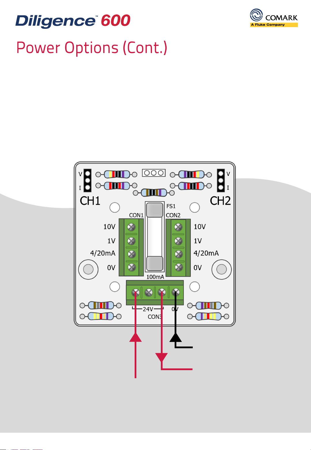
You may also require separate power directly to your transducers, depending
on the manufacturer recommendations.
Part No: 18477 (3616817)
This 24V Power Supply with
interchangeable mains plugs to
suit your region is designed for
use with the Multi-Parameter 2-
Way Adaptor Box (RF615B).
Part No: RF602Y (5306378)
Use the Y Adaptor should you wish to
add TWO Multi-Parameter 2-Way
Adaptor Boxes to your transmitter in
order to maximize the number of
external channels you can measure.

The Multi-Parameter 2-Way Adaptor Box (RF615B) is opened by undoing the
two screws located on the rear (underside) of the device. Inside you will see the
PCB with several different terminals, as indicated below. All connections are
made using the screw terminals provided. Please note that you might need to
insert two wires into any of the screw terminals.
Copyright © 2022 Comark Instruments
Voltage/Current Selectors
24V Power In/Out
(If Required)
Transducer Connector Inputs

Copyright © 2022 Comark Instruments
The Adaptor Box is divided into two channels which are labelled (CH1 and CH2)
as indicated below. If two adaptor boxes are used, via a Y Adaptor (RF602Y),
then channel 1 will be reflected as channel 3 on the connected transmitter,
and channel 2 as channel 4.
Each channel is independent, so can either be configured for a voltage input, or
for a current input. CH1 and CH2 need not have the same configuration.
The selection of either voltage or current is made using the included shorting
links as indicated above. Please ensure that you have made the correct
selection else there will be errors in the readings.
It is recommended that only persons with some prior knowledge of electrical
circuits, undertake any required wiring of the Adaptor Box(es).
Voltage
Selection
Current
Selection

The Multi-Parameter 2-Way Adaptor Box (RF615B) is pre-fitted with three cable
grommets which should be used for bringing cables in and out of the housing.
The Adaptor Box also includes connections for a 24V mains power supply unit
(PSU) in order that power can be supplied to connected devices.
It should be noted that some transducers require a separate PSU. In the case of
4-20mA transducers, some are loop-powered, with the connections in series.
Copyright © 2022 Comark Instruments
24V Power In/Out
(If Required)
Cable Grommets Cable Grommets

The 24V PSU connection to the Adaptor Box (RF615B) includes two additional
connectors, to allow power output to the transducer. The ground connection
should be used for both the PSU and connections to 0V on the transducers.
In some special cases, current (4-20mA) transducers do not have a separate
output for the signal and rely on the two-wire connection for both sensor power
and the output to the loop. In such cases special attention should be paid to the
connections required. An example of wiring for loop-power is given further on.
Copyright © 2022 Comark Instruments
24V PSU
Input
Power to Transducer
0V Input from Transducer

Copyright © 2022 Comark Instruments
Here the transducer has four connections, two for power in and two for the
signal out. It is possible that the ground input may be shared with the 0V
output thus having only three connections instead of four.
It may not be necessary to use the power connections inside the Adaptor Box
as power can be provided direct to the transducer. However, if using two
voltage transducers, then using the Adapter Box connections would allow
both to be powered from a single PSU. Always ensure that you use the 0-1V or
0-10V input as per the transducer selection.
24V PSU
Input
0V
24V
Ground
0-10V
Voltage
Transducer
PSU 0V

In this example, the transducer has four connections, two for power in and two
for the signal out. It is possible that the ground input may be shared with the
0V output thus having only three connections instead of four.
In this instance the 4-20mA current transducer is not loop-powered and has
separate power input and current output.
Copyright © 2022 Comark Instruments
24V PSU
Input
0V
24V
Loop Return
4-20mA
Current
Transducer
PSU 0V

Copyright © 2022 Comark Instruments
With this option, the transducer is powered by the loop current flowing around
the circuit. Two loop-powered transducers can still be connected, but the
wiring of each should be kept separate. The second transducer should be
wired in parallel with the first to ensure that there are two current loops. If you
are breaking into an existing current loop, i.e., in a factory environment, you do
not need the additional PSU connection. Simply connect the existing current
loop to the 0V/Ground connector and the 4/20mA connector. If the readings
on the Transmitter (RF615) are reversed, then simply swap the connections.
24V PSU
Input
Input
Output
Current
Transducer
(Loop-Powered)
PSU 0V

Environmental Protection
The Multi-Parameter 2-Way Adaptor Box (RF615B) is not waterproof and
therefore should not be used in damp or wet environments. Nor is it rated for
intrinsically safe applications.
Before Connecting Power
We recommend that all wiring is checked thoroughly prior to connecting
power. This is especially important if multiple transducers are being
connected via the Multi-Parameter 2-Way Adaptor Box (RF615B) to the
Diligence 600 WiFi Multi-Parameter Transmitter (RF615), or if there is a mix of
voltage and current transducers. Damage can potentially occur if the
transducers are incorrectly wired.
We recommend connecting everything to the Transmitter (RF615) initially. If
the input is shorted or 24V applied directly to the current input, then the fuse
will blow. The fuse is rated for 100mA.
Once all internal connections have been made the case should be
reassembled and secured with the two supplied screws.
Commissioning
In order to now see data from any connected transducer(s), the Diligence WiFi
Multi-Parameter Transmitter(s) will need to be tasked.
Please refer to the Diligence Cloud platform help section or the Diligence 600
Reference Manual for further information on this and general transmitter
related functions.
Copyright © 2022 Comark Instruments

Each Comark product is warranted to be free from defects in material and workmanship under normal use
and service. The warranty period is one (1) year, unless otherwise stated, and the warranty period begins on
the date of shipment. Temperature probes are warranted for six (6) months.
The warranty extends only to the original buyer or end-user of a Comark authorized reseller. This warranty
does not cover damage resulting from normal wear and tear, abuse, misuse, accidental breakage, negligence,
defects caused by modifications, repair and servicing not made or authorised by Comark Instruments,
damage caused by handling, operating, storing, or using the product outside the intended uses described by
our product literature. Disposable batteries are also exempt from warranty.
Comark’s warranty obligation is limited, at Comark’s option, to refund of the purchase price, free of charge
repair, or replacement of a defective product returned within the warranty period. Products must be returned
to Comark or one of Comark’s authorized service agents.
This warranty is the buyer’s sole and exclusive remedy and is in lieu of all other warranties, express or implied,
including but not limited to any implied warranty of fitness for a particular purpose. Comark shall not be liable
for any special, indirect, incidental or consequential damages or losses, including loss of data, whether arising
from breach of warranty or based on contract, tort, reliance or any other theory. Since some countries or
states do not allow limitation of the term of an implied warranty, or exclusion or limitation of incidental or
consequential damages, the limitations and exclusions of this warrant may not apply to every buyer.
Comark Instruments
P.O. Box 500
Beaverton, OR 97077, USA
Toll Free: (800) 555 6658
Email: [email protected]
Comark Instruments
52 Hurricane Way
Norwich, Norfolk, NR6 6JB
United Kingdom
Tel: +44 (0) 207 942 0712
Email: [email protected]
All rights reserved. Data subject to alteration without
notice. All trademarks are the property of their respective
owners. Modification of this document is not permitted
without written permission from Comark Instruments.
0451 0775
Copyright © 2022 Comark Instruments 20825-1 | May 2022
Other manuals for Comark Diligence 600
2
Table of contents
Other Fluke Receiver manuals