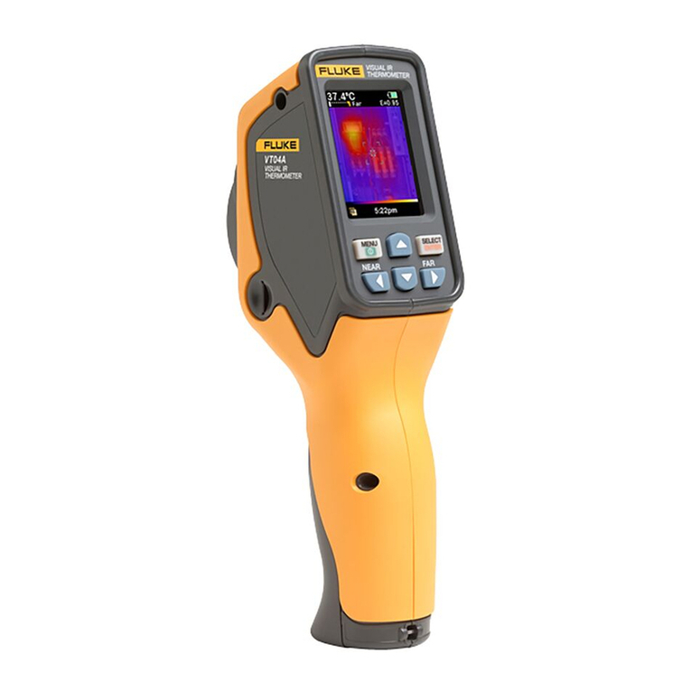
Fluke VT06 User manual

VT06/VT08™
Visual IR Thermometer
Users Manual
É
October 2021 (English)
© 2021 Fluke Corporation. All rights reserved.
Specifications are subject to change without notice.
All product names are trademarks of their respective companies.

LIMITED WARRANTY AND LIMITATION OF LIABILITY
Each Fluke product is warranted to be free from defects in material and workmanship under normal use
and service. The warranty period is 1 year and begins on the date of shipment. Parts, product repairs, and
services are warranted for 90 days. This warranty extends only to the original buyer or end-user customer
of a Fluke authorized reseller, and does not apply to fuses, disposable batteries, or to any product which,
in Fluke's opinion, has been misused, altered, neglected, contaminated, or damaged by accident or
abnormal conditions of operation or handling. Fluke warrants that software will operate substantially in
accordance with its functional specifications for 90 days and that it has been properly recorded on non-
defective media. Fluke does not warrant that software will be error free or operate without interruption.
Fluke authorized resellers shall extend this warranty on new and unused products to end-user customers
only but have no authority to extend a greater or different warranty on behalf of Fluke. Warranty support is
available only if product is purchased through a Fluke authorized sales outlet or Buyer has paid the
applicable international price. Fluke reserves the right to invoice Buyer for importation costs of repair/
replacement parts when product purchased in one country is submitted for repair in another country.
Fluke's warranty obligation is limited, at Fluke's option, to refund of the purchase price, free of charge
repair, or replacement of a defective product which is returned to a Fluke authorized service center within
the warranty period.
To obtain warranty service, contact your nearest Fluke authorized service center to obtain return
authorization information, then send the product to that service center, with a description of the difficulty,
postage and insurance prepaid (FOB Destination). Fluke assumes no risk for damage in transit. Following
warranty repair, the product will be returned to Buyer, transportation prepaid (FOB Destination). If Fluke
determines that failure was caused by neglect, misuse, contamination, alteration, accident, or abnormal
condition of operation or handling, including overvoltage failures caused by use outside the product’s
specified rating, or normal wear and tear of mechanical components, Fluke will provide an estimate of
repair costs and obtain authorization before commencing the work. Following repair, the product will be
returned to the Buyer transportation prepaid and the Buyer will be billed for the repair and return
transportation charges (FOB Shipping Point).
THIS WARRANTY IS BUYER'S SOLE AND EXCLUSIVE REMEDY AND IS IN LIEU OF ALL OTHER
WARRANTIES, EXPRESS OR IMPLIED, INCLUDING BUT NOT LIMITED TO ANY IMPLIED WARRANTY OF
MERCHANTABILITY OR FITNESS FOR A PARTICULAR PURPOSE. FLUKE SHALL NOT BE LIABLE FOR ANY
SPECIAL, INDIRECT, INCIDENTAL OR CONSEQUENTIAL DAMAGES OR LOSSES, INCLUDING LOSS OF
DATA, ARISING FROM ANY CAUSE OR THEORY.
Since some countries or states do not allow limitation of the term of an implied warranty, or exclusion or
limitation of incidental or consequential damages, the limitations and exclusions of this warranty may not
apply to every buyer. If any provision of this Warranty is held invalid or unenforceable by a court or other
decision-maker of competent jurisdiction, such holding will not affect the validity or enforceability of any
other provision.
11/99
Fluke Corporation
P.O. Box 9090
Everett, WA 98206-9090
U.S.A.
i
Table of Contents
Introduction................................................................................................................................... 1
Contact Fluke Corporation...................................................................................................... 1
Safety Information...................................................................................................................... 2
Product Familiarization ............................................................................................................. 2
Features................................................................................................................................. 2
Specifications...................................................................................................................... 2
The Product.......................................................................................................................... 2
Trigger.................................................................................................................................... 4
Control Panel ....................................................................................................................... 4
Display Screen .................................................................................................................... 5
Menu Controls..................................................................................................................... 6
Basic Operation ........................................................................................................................... 7
Power On and Power Off the Product........................................................................ 7
Focus ...................................................................................................................................... 7
Laser Pointer........................................................................................................................ 7
Camera mode ...................................................................................................................... 7
Capture and Save an Image ........................................................................................... 8
Save Images to a PC ......................................................................................................... 8
Main Menu ..................................................................................................................................... 9
Gallery..................................................................................................................................... 11
Review............................................................................................................................ 11
Delete all images ....................................................................................................... 11
TempRange .......................................................................................................................... 12
Emissivity .............................................................................................................................. 12
ROIMeasure.......................................................................................................................... 13
Alarm....................................................................................................................................... 13
DateTime............................................................................................................................... 14
Reset....................................................................................................................................... 14
PIPTransparent (VT08 Only)........................................................................................... 15
Fluke VT Report Desktop Software ..................................................................................... 15
Accessories .................................................................................................................................. 16
Maintenance ................................................................................................................................. 16
Clean the Case .................................................................................................................... 16
Lens Care .............................................................................................................................. 16
Battery Care ......................................................................................................................... 16
Charge Batteries ................................................................................................................17

ii
VT06/VT08
Users Manual

1
Introduction
The Fluke VT06/VT08 Visual IR Thermometers (the Product or Meter) are hand-held, infrared
imaging cameras for use in many applications. These applications include equipment
troubleshooting, preventive and predictive maintenance, building diagnostics, and research
and development.
The Meter displays thermal images on a high-visibility, industrial-quality LCD screen. The
Meter can save images to internal memory. You can transfer images and data stored in internal
memory to a PC through a direct USB connection to the PC.
A rugged, rechargeable lithium-ion smart battery provides power to the Meter. Direct ac power
is accessible with the included ac power adapter.
Contact Fluke Corporation
Fluke Corporation operates worldwide. For local contact information, go to our website:
www.fluke.com.
To register your product, or to view, print, or download the latest manual or manual
supplement, go to our website.
+1-425-446-5500 fluke-info@fluke.com
Fluke Corporation
P.O. Box 9090
Everett WA 98206-9090
U.S.A.
Fluke Europe B.V.
P.O. Box 1186
5602 BD Eindhoven
The Netherlands

VT06/VT08
Users Manual
2
Safety Information
General Safety Information is in the printed Safety Information document that ships with the
Product and on the www.fluke.com website. More specific safety information is listed where
applicable.
Product Familiarization
The manual explains features for multiple models. Because models have different features, some
of the information in the manual might not apply to your Meter.
Note
Unless otherwise specified, the figures in this document show the VT08 Visual IR
Thermometer.
Features
Table 1 shows the features of the Product.
Specifications
Complete specifications are at www.fluke.com. See the VT06/VT08 Product Specifications.
The Product
Ta b l e 2 shows the front of Product VT08.
Table 1. Features
Feature VT06 VT08
Focus/Image Enhancement
Fixed focus
Visible Light Camera
Picture-in-Picture (PIP)
Light/Laser
LED Light
Laser

VT06/VT08
Users Manual
4
Trigger
The Trigger is located in the standard trigger position for a pistol-grip device.
Use the Trigger to capture and save an image. The Trigger is also the laser pointer switch. From
any menu, use the Trigger to return to Camera mode.
Control Panel
Use the control panel to change parameters or select functions and options. You can also use P
to power on or power off the Product. For the VT08 device only, you can also use the Obutton
to turn on or turn off the LED Light. Ta b l e 4 shows the functions of the buttons on the Control
Panel.
Table 3. Back of the Products
VT08 VT06
VT08
Item Description Item Description
AVisual Light Camera Lens DLED
BInfrared Camera Lens ETrigger
CLaser Pointer (the Japanese model
has no laser pointer) FAC Power Supply with Mains
Adapters
VT06
Item Description Item Description
ALaser Pointer (the Japanese model
has no laser pointer) CTrigger
BInfrared Camera Lens DAC Power Supply with Mains
Adapters
1
2
3
4
5
1
2
3
6 4
VT08 VT06

Visual IR Thermometer
Product Familiarization
5
Display Screen
The display screen is the primary user interface of the Product. The display screen has a backlight
for work in dimly lit spaces.
Table 5 shows the default information on the screen of the Product.
Table 4. Control Panel
Button Description
O
Push to open the Main Menu.
Push and hold for 2 seconds to power on or power off the LED Light (VT08
only).
Within a menu or submenu:
Push to save the change and go back to the previous menu.
Push to perform the function.
P
Push and hold for 2 seconds to power on or power off the Product.
Push to cancel the change and go back to the previous menu.
W
Push to switch the Camera mode (VT08 only).
Push to move up the cursor and highlight an option.
Within a submenu, push to increase a parameter value during parameter
editing.
X
Push to switch the Camera mode (VT08 only).
Push to move down the cursor and highlight an option.
Within a submenu, push to decrease a parameter value during parameter
editing.

VT06/VT08
Users Manual
6
Menu Controls
The following choices describe how to use the menus to change and view settings:
1. Push Oin Camera mode to open the Main Menu.
2. On the Main Menu, push Pto return to live Camera mode.
3. On the Main Menu, push Wor Xto move the cursor and highlight an option.
4. On the Main Menu, push Oto open a submenu. Tab le 6 describes the Main Menu options.
Table 5. D i splay
Item Description Item Description
ACenter point temperature GTemperature range higher value
B
Region of Interest Measure
(ROIMeasure) area
This area outlines the high and low
temperature markers in its spot box.
HROIMeasure high temperature
marker
CROIMeasure low temperature marker I
Range bar
The range of colors in the
palette mapped to a certain
range of temperatures
DCenter point marker JTemperature range lower value
ETime KEmissivity value
F
Status information for Battery status,
SD card status, Laser status, High
temperature alarm status, Low
temperature alarm status, and USB
connect status
1 6
7
9
10
11
5
2
3
4
8

Visual IR Thermometer
Basic Operation
7
5. On the submenu, push Pto return to the previous menu.
6. To change and view settings on the submenu, refer to the Gallery and Camera Info sections.
7. Push the Trigger to close a menu or submenu and return to live Camera mode.
Basic Operation
Power On and Power Off the Product
Before you use the Product for the first time, charge the battery. See Charge Batteries.
To power on the Product, push and hold Pfor 2 seconds.
To power off the Product, push and hold Pfor 2 seconds.
Note
All thermal Meters need sufficient warm-up time for accurate temperature measurements
and best image quality. Warm-up time can vary by model and environmental conditions.
Although most Meters are fully warmed up in 3 minutes to 5 minutes, wait a minimum of
10 minutes if the most accurate temperature measurement is important to your
application. When you move a Meter between environments with large differences in
ambient temperature, allow for additional adjustment time.
Note
If the Product crashes, push and hold Pfor 3 seconds to power off the Product.
Focus
The VT06/VT08 thermometer is a focus-free product, which means that users do not need to do
anything after receiving it. The Product can ensure that the image is clearly set within 0.5 m and
1.2 m.
Laser Pointer
The Meter has a laser pointer. The laser pointer is a sighting aid and is offset from the infrared
camera. As a result, the laser dot does not always represent the exact center of the image.
The laser dot does not appear on infrared-only or PIP images. The laser dot does appear on
visible-only images. You will not be able to see the laser dot in the visible channel of the PIP image
if the dot is obscured by the center point marker graphic.
Pull the Trigger to turn on the laser pointer and release the Trigger to turn off the laser pointer.
Camera mode
The VT08 Meter has the infrared, visible light, and PIP Camera modes, as shown in Figure 1. The
VT06 Meter has only infrared mode.

VT06/VT08
Users Manual
8
Figure 1. VT08 Camera Modes
To switch the Camera mode:
1. Push Wto open a list of Camera modes.
2. Push Wor X to switch to a different Camera mode.
Capture and Save an Image
You can capture and save images in Camera mode.
To capture and save an image:
1. In Camera mode, focus on a target.
2. Pull and release the Trigger to capture and freeze the image.
3. Within 2 seconds, pull and release the Trigger again or push Oto save the image.
If you decide to discard the image, wait longer than 2 seconds to push Oor push P.
Save Images to a PC
To save images to a PC with the USB cord:
1. Power on the Product.
2. Connect one end of the USB cord to the USB port on the Product and the other end of the USB
cord to a USB port on a PC.
The PC recognizes the Product as an external memory storage device.
3. On the PC:
a. Browse to the directory on the Product.
b. Copy and paste or drag the images to a directory on the PC.
Visible Light Mode
Infrared Mode PIP Camera Mode

Visual IR Thermometer
Main Menu
9
4. Remove the USB cord from the PC and the Product.
Main Menu
The Main Menu shows the available options for the Meter.
To view and select menu options:
1. On the Product, push Oto open the Main Menu.
2. Push Wor X to find the item you want.
3. Push Oto accept your selection.
4. Pull the Trigger to return to Camera mode.
Table 6. Main Menu Options
Menu Option Function
Gallery
View or delete an image:
Use Review to look at an image in the internal memory
storage. You can delete this image if you do not need
it.
Use Delete all images to remove all of the images in
the internal memory storage.
See Gallery.
Te m p R a n g e Set the temperature range to use. See Te m p R a n g e .
Emissivity Set the emissivity. See Emissivity.
Palette
Set the palette to use on the image:
WhiteHot
IronRed
HotIron
RainBow1
RainBow2
Arctic

VT06/VT08
Users Manual
10
CenterPoint
Use the center point marker to help you with temperature
measurement. The Meter screen shows the center point
temperature. When you use the center point marker to aim
at the target, you can get the target temperature. Options
are:
On
Off
After you power on the setting and return to Camera
mode, you see a marker in the center of screen.
Te m p U n i t
Set the temperature unit to use:
Celsius
Fahrenheit
The option to set a TempUnit is not available in all
countries.
ROIMeasure Set the measure area to help with temperature
measurement. See ROIMeasure.
Alarm Set the alarm parameters. See Alarm.
Reflmeasure Set the reflected temperature.
Distance
The farther the distance, the weaker the infrared energy.
You can set the distance between the Meter and the
target to make the temperature measurement more
accurate.
AutoShut
You can set an automatic shutdown to save battery
power. The Meter automatically shuts down after the set
time has passed without operation.
ScreenBright You adjust screen brightness to adapt to the ambient
light.
Laser Turn on or turn off the laser setting switch. For information
about using the laser, see Laser Pointer.
Table 6. Main Menu Options (cont.)
Menu Option Function

Visual IR Thermometer
Main Menu
11
Gallery
The following sections describe the options available in the Gallery submenu.
Review
You can review an image in the internal memory storage and delete the image if you do not
need it.
To review and delete an image:
1. In the Gallery submenu, push Wor Xto highlight Review.
2. Push Oto review the first image.
3. Push Wto review the previous image or push Xto review the next image.
4. Push Oand push Wor Xto highlight √, then push Oagain to delete this image.
Delete all images
To delete all images at the same time:
1. In the Gallery submenu, push Wor Xto highlight Delete all images.
2. Push Oand push Wor Xto highlight √, then push Oagain to delete all images.
DateTime Set the date and time. See DateTime.
Language
Reset Reset the Meter settings. See Reset.
Format SD
Format the internal memory storage. After you begin the
formatting, be sure to wait until you see the Formatted
message before making another selection.
PIPTransparent
(VT08 only)
Set the transparency of an infrared picture in PIP mode.
See PIPTransparent (VT08 Only).
Camera Info View the Meter information including version, firmware
version, serial number, SD card status, and ID.
Table 6. Main Menu Options (cont.)
Menu Option Function
Select the language displayed on the screen:
English Simplified Chinese
Korean Traditional Chinese
Japanese

VT06/VT08
Users Manual
12
TempRange
When measuring temperature, you need to use the appropriate temperature range, which
depends on the target temperature. The Meter has these temperature ranges:
-20°Cto150°C(-4°Fto302°F)
100 °C to 400 °C (212 °F to 752 °F)
The Meter can automatically use the appropriate range based on the target temperature if you
set the TempRange to Auto in the Main Menu.
Emissivity
All objects radiate infrared energy. The actual surface temperature and emissivity of the target
affect the quantity of energy radiated. The Meter senses the infrared energy from the surface
of the target and uses the data to calculate an estimated temperature value. Many common
materials such as wood, water, skin, cloth, and painted surfaces, including metal, radiate
energy well and have a high emissivity factor of ≥90 % (or 0.90). The Meter measures
temperatures accurately on targets with a high emissivity.
Shiny surfaces or unpainted metals do not radiate energy well and have a low emissivity factor
of <0.60. For the Meter to calculate a more accurate estimate of the actual temperature of
targets with a low emissivity, adjust the emissivity setting.
WWarning
To prevent personal injury, see emissivity information for actual temperatures.
Reflective objects result in lower than actual temperature measurements. These
objects pose a burn hazard.
Set emissivity as a direct value or from a list of emissivity values for some common materials.
Note
Surfaces with an emissivity of <0.60 make it difficult to determine reliable and
consistent actual temperatures. The lower the emissivity, the greater the potential of
error when the Meter calculates the temperature measurement because more of the
energy reaching the camera is specified as background temperature. This is also true
when adjustments to the emissivity and reflected background adjustments are
performed properly.
To adjust emissivity:
1. In the Emissivity submenu, push Wor Xto select which emissivity to use, or select
SelfDefine.
2. If you select SelfDefine, push Oand Wor Xto manually set the emissivity.
3. Push Oagain to save.
4. Push Pto return to the previous menu.

Visual IR Thermometer
Main Menu
13
ROIMeasure
Use this setting to determine the measure area to help with temperature measurement. In the
measure area, high and low temperature markers automatically track the highest temperature and
lowest temperature. The images in Figure 2 show the types of measure area that you can select.
Figure 2. Types of ROIMeasure Areas
Alarm
Use this setting to adjust the alarm parameters. Tabl e 7 shows the options in the Alarm submenu.
To set the alarm:
1. In the Alarm submenu, push Oto turn on or turn off the alarm.
2. When the alarm is on:
a. Push Xto highlight High.
b. Push Oto turn on the high-temperature alarm.
c. Push Xto highlight High temperature value.
d. Push Oto begin editing and push Wor Xto adjust the high temperature value.
e. Push Oto stop editing and save the changes.
Table 7. Ala rm Menu
Option Suboption Description
OFF Turn off the alarm.
ON
High Turn on or turn off the high-temperature alarm; set
the high-temperature alarm value.
High temperature value
Low Turn on or turn off the low-temperature alarm; set the
low-temperature alarm value.
Low temperature value
Center Center with full screen
Center with small
spot box
Center with moderate
spot box

VT06/VT08
Users Manual
14
3. Adjust the Low and Low temperature value settings as needed:
a. Push Xto highlight Low.
b. Push Oto turn on the low-temperature alarm.
c. Push Xto highlight Low temperature value.
d. Push Oto begin editing and push Wor Xto adjust the low temperature value.
e. Push Oto stop editing and save the changes.
DateTime
The date is displayed as YY/MM/DD and the time shows as 24 hour or 12 hour. Use the steps in
this section to set the date and time on the Meter.
To set the date:
1. In the DateTime submenu push Wor Xto highlight Ye a r .
2. Push Oand then push Wor Xto find the year you want.
3. Push Oto save the setting.
4. To set the month and day, follow the first step 1 through step 3 in this section, using step 1 to
highlight Month and Day, as appropriate.
To set the time:
1. Push Wor Xto highlight 24H.
2. Push Oand then push Wor Xto select 24 hour or 12 hour.
3. Push Oto save the setting.
4. If you selected 12 hour, highlight PM or AM and push O, then push Wor Xto select PM
or AM.
5. Push Oto save the setting.
6. To set the hour and minute, follow step 1 through step 5, using step 1 and step 2 to highlight
Hour and Minute, as appropriate.
Reset
You can reset the following settings to their default values.
Menu Default
TempRange -20 °C to 150 °C (-4 °F to 302 °F)
Emissivity 0.95
Palette IronRed
CenterPoint ON
Te m p U n i t ° C
ROIMeasure Big

Visual IR Thermometer
Fluke VT Report Desktop Software
15
To re s e t :
1. In the Reset submenu, push Wor Xto highlight √.
2. Push Oto reset, then go to the Language submenu.
3. Set the language.
PIPTransparent (VT08 Only)
Use these steps to set the transparency of an infrared picture in PIP mode. The 0, 30 %, 60 %, and
90 % levels are available. As the level increases, the transparency becomes greater. The images in
Figure 3 show the transparency levels.
Figure 3. Transparency Levels
Fluke VT Report Desktop Software
Fluke VT Report desktop software for a PC is available to use with the Product and contains
features to analyze images, organize data and information, and make professional reports.
You can download the Fluke VT Report software and use it to edit image files.
To download the Fluke VT Report desktop software:
1. Go to https://www.fluke.com/en-us/support/software-downloads/software-for-fluke-infrared-
cameras.
2. On the website, follow the instructions to download the software to the PC.
Alarm Off
RelfMeasure 23 °C (73 °F)
AutoShut Disable
ScreenBright Medium
Laser Off
DateTime 24H
Menu Default
0 % 90 %
30 % 60 %

VT06/VT08
Users Manual
16
Note
You must have Administrator privileges for your computer to install the software.
3. On the PC, follow the instructions to install the Fluke VT Report software.
4. Restart the PC when installation is complete.
Accessories
See www.fluke.com for a list of accessories available for the Product.
Maintenance
The Product requires minimum maintenance.
Clean the Case
Clean the case with a damp cloth and a weak soap solution. Do not use abrasives, isopropyl
alcohol, or solvents to clean the case.
Lens Care
WCaution
To prevent damage to the infrared lens:
Carefully clean the infrared lens. The lens has a delicate anti-reflective coating.
Do not clean the lens too vigorously because this can damage the anti-reflective
coating.
To clean the lens:
1. Use a pressurized can of air or a dry nitrogen-ion gun, if available, to blow off the particulates
from the lens surface.
2. Soak a lint-free cloth in a commercial lens cleaning liquid that contains alcohol, ethyl alcohol,
or isopropyl alcohol.
3. Squeeze the cloth to remove excess liquid.
4. Wipe the lens surface in one circular motion and discard the cloth.
5. If needed, repeat with a new lint-free cloth.
Battery Care
To get the best performance from the lithium-ion battery:
Do not charge the Product for more than 24 hours because reduced battery life might result.
Charge the Product for at least 2.5 hours every six months for maximum battery life. Without
use, the battery will self-discharge in approximately six months.
Other manuals for VT06
1
This manual suits for next models
1
Table of contents
Other Fluke Thermometer manuals

Fluke
Fluke 62 MAX User manual

Fluke
Fluke 1521 User manual

Fluke
Fluke 51 User manual

Fluke
Fluke 51 II Series User manual

Fluke
Fluke 54 Series II User manual

Fluke
Fluke 566 User manual

Fluke
Fluke COMARK KM400 User manual

Fluke
Fluke 67 MAX Use and care manual

Fluke
Fluke 2190A User manual

Fluke
Fluke 561 HVACPro User manual

Fluke
Fluke 2190A User manual

Fluke
Fluke 62 MAX User manual

Fluke
Fluke 50D Use and care manual

Fluke
Fluke 572-2 Instruction manual

Fluke
Fluke Series II User manual

Fluke
Fluke CNX t3000 Use and care manual

Fluke
Fluke 56 Series User manual

Fluke
Fluke CNX t3000 User manual

Fluke
Fluke 61 User manual

Fluke
Fluke 62 MAX User manual