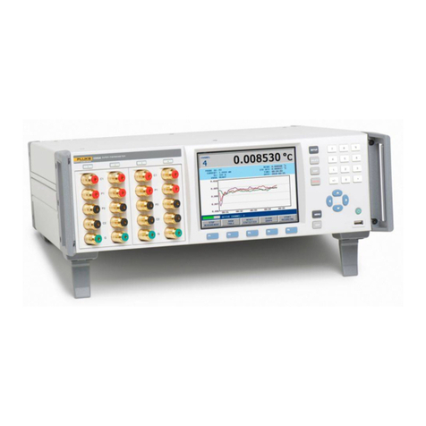
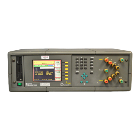
Fluke 1560 Black Stack User manual

1560 Black Stack
Thermometer Readout
User’s Guide
Rev. 932001
Hart Scientific

Limited Warranty & Limitation of Liability
Each product from Fluke Corporation, Hart Scientific Division ("Hart") is warranted to be free from de-
fects in material and workmanship under normal use and service. The warranty period is 2 years for the
Black Stack. The warranty period begins on the date of the shipment. Parts, product repairs, and services
are warranted for 90 days. The warranty extends only to the original buyer or end-user customer of a Hart
authorized reseller, and does not apply to fuses, disposable batteries or to any other product, which in
Hart's opinion, has been misused, altered, neglected, or damaged by accident or abnormal conditions of
operation or handling. Hart warrants that software will operate substantially in accordance with its func-
tional specifications for 90 days and that it has been properly recorded on non-defective media. Hart does
not warrant that software will be error free or operate without interruption. Hart does not warrant calibra-
tions on the Black Stack.
Hart authorized resellers shall extend this warranty on new and unused products to end-user customers
only but have no authority to extend a greater or different warranty on behalf of Hart. Warranty support is
available if product is purchased through a Hart authorized sales outlet or Buyer has paid the applicable
international price. Hart reserves the right to invoice Buyer for importation costs of repairs/replacement
parts when product purchased in one country is submitted for repair in another country.
Hart's warranty obligation is limited, at Hart's option, to refund of the purchase price, free of charge re-
pair, or replacement of a defective product which is returned to a Hart authorized service center within
the warranty period.
To obtain warranty service, contact your nearest Hart authorized service center or send the product, with
a description of the difficulty, postage, and insurance prepaid (FOB Destination), to the nearest Hart au-
thorized service center. Hart assumes no risk for damage in transit. Following warranty repair, the prod-
uct will be returned to Buyer, transportation prepaid (FOB Destination). If Hart determines that the
failure was caused by misuse, alteration, accident or abnormal condition or operation or handling, Hart
will provide an estimate or repair costs and obtain authorization before commencing the work. Following
repair, the product will be returned to the Buyer transportation prepaid and the Buyer will be billed for
the repair and return transportation charges (FOB Shipping Point).
THIS WARRANTY IS BUYER'S SOLE AND EXCLUSIVE REMEDY AND IS IN LIEU OF ALL
OTHER WARRANTIES, EXPRESS OR IMPLIED, INCLUDING BUT NOT LIMITED TO ANY IM-
PLIED WARRANTY OF MERCHANTABILITY OR FITNESS FOR A PARTICULAR PURPOSE.
HART SHALL NOT BE LIABLE FOR ANY SPECIAL, INDIRECT, INCIDENTAL. OR CONSE-
QUENTIAL DAMAGES OR LOSSES, INCLUDING LOSS OF DATA, WHETHER ARISING FROM
BREACH OF WARRANTY OR BASED ON CONTRACT, TORT, RELIANCE OR ANY OTHER
THEORY.
Since some countries or states do not allow limitation of the term of an implied warranty, or exclusion or
limitation of incidental or consequential damages, the limitations and exclusions of this warranty may not
apply to every buyer. If any provision of this Warranty is held invalid or unenforceable by a court of com-
petent jurisdiction, such holding will not affect the validity or enforceability of any other provision.
Rev. 932001
Fluke Corporation, Hart Scientific Division
799 E. Utah Valley Drive • American Fork, UT 84003-9775 • USA
Phone: +1.801.763.1600 • Telefax: +1.801.763.1010
E-mail: [email protected]
www.hartscientific.com
Subject to change without notice. • Copyright © 2005 • Printed in USA

Table of Contents
1 Before You Start . . . . . . . . . . . . . . . . . . . . . . . . . . 1
1.1 Symbols Used . . . . . . . . . . . . . . . . . . . . . . . . . . . . 1
1.2 Safety Information . . . . . . . . . . . . . . . . . . . . . . . . . . 2
1.2.1 Warnings . . . . . . . . . . . . . . . . . . . . . . . . . . . . . . . . . . . . . 2
1.2.2 Cautions . . . . . . . . . . . . . . . . . . . . . . . . . . . . . . . . . . . . . 3
1.3 Authorized Service Centers. . . . . . . . . . . . . . . . . . . . . . 3
2 Introduction . . . . . . . . . . . . . . . . . . . . . . . . . . . . 5
2.1 Features . . . . . . . . . . . . . . . . . . . . . . . . . . . . . . . . 5
2.2 Components . . . . . . . . . . . . . . . . . . . . . . . . . . . . . 7
2.2.1 Base Microprocessor . . . . . . . . . . . . . . . . . . . . . . . . . . . . . . . 7
2.2.1.1 Display . . . . . . . . . . . . . . . . . . . . . . . . . . . . . . . . . . . . . . . . . . 7
2.2.1.2 Buttons . . . . . . . . . . . . . . . . . . . . . . . . . . . . . . . . . . . . . . . . . 11
2.2.1.3 Serial RS-232 Interface . . . . . . . . . . . . . . . . . . . . . . . . . . . . . . . . . 12
2.2.1.4 Power Supply . . . . . . . . . . . . . . . . . . . . . . . . . . . . . . . . . . . . . . 12
2.2.1.5 Module Bus . . . . . . . . . . . . . . . . . . . . . . . . . . . . . . . . . . . . . . . 12
2.2.2 Add-On Modules . . . . . . . . . . . . . . . . . . . . . . . . . . . . . . . . 13
2.3 Data Processing . . . . . . . . . . . . . . . . . . . . . . . . . . . 14
2.3.1 Inputs . . . . . . . . . . . . . . . . . . . . . . . . . . . . . . . . . . . . . . 14
2.3.2 Sampling Control . . . . . . . . . . . . . . . . . . . . . . . . . . . . . . . . 14
2.3.3 Input Average . . . . . . . . . . . . . . . . . . . . . . . . . . . . . . . . . . 14
2.3.4 Temperature Conversion . . . . . . . . . . . . . . . . . . . . . . . . . . . . 14
2.3.5 Unit Conversion. . . . . . . . . . . . . . . . . . . . . . . . . . . . . . . . . 16
2.3.6 Primary Measurement Display . . . . . . . . . . . . . . . . . . . . . . . . . 16
2.3.7 Graph and Scroll Windows . . . . . . . . . . . . . . . . . . . . . . . . . . . 16
2.3.8 Memory . . . . . . . . . . . . . . . . . . . . . . . . . . . . . . . . . . . . . 16
2.3.9 Printer Outputs . . . . . . . . . . . . . . . . . . . . . . . . . . . . . . . . . 16
2.3.10 Statistics. . . . . . . . . . . . . . . . . . . . . . . . . . . . . . . . . . . . . 16
2.3.11 Output Routing . . . . . . . . . . . . . . . . . . . . . . . . . . . . . . . . . 16
2.3.12 Display Data Fields . . . . . . . . . . . . . . . . . . . . . . . . . . . . . . . 17
2.3.13 Data Output Channels. . . . . . . . . . . . . . . . . . . . . . . . . . . . . . 17
3 Specifications and Environmental Conditions . . . . . . . . . 19
3.1 Specifications . . . . . . . . . . . . . . . . . . . . . . . . . . . . 19
3.2 Environmental Conditions. . . . . . . . . . . . . . . . . . . . . . 19
4 General Operation . . . . . . . . . . . . . . . . . . . . . . . . 21
4.1 Installing New Modules . . . . . . . . . . . . . . . . . . . . . . . 21
4.2 AC Power Source . . . . . . . . . . . . . . . . . . . . . . . . . . 23
4.3 Power On Self-Test . . . . . . . . . . . . . . . . . . . . . . . . . 23
4.4 Adjusting the Screen Contrast. . . . . . . . . . . . . . . . . . . . 23
iii

4.5 Making Measurements . . . . . . . . . . . . . . . . . . . . . . . 23
4.5.1 Selecting Input Channels . . . . . . . . . . . . . . . . . . . . . . . . . . . . 23
4.5.2 Selecting the Probe Characterization . . . . . . . . . . . . . . . . . . . . . . 25
4.5.3 Measuring One Channel . . . . . . . . . . . . . . . . . . . . . . . . . . . . 26
4.5.4 Scanning Channels . . . . . . . . . . . . . . . . . . . . . . . . . . . . . . . 26
4.5.5 Displaying Measurement Data . . . . . . . . . . . . . . . . . . . . . . . . . 26
5 Soft-Key Functions . . . . . . . . . . . . . . . . . . . . . . . . 29
5.1 Input Menu . . . . . . . . . . . . . . . . . . . . . . . . . . . . . 29
5.1.1 Measure . . . . . . . . . . . . . . . . . . . . . . . . . . . . . . . . . . . . . 29
5.1.2 Primary Channel . . . . . . . . . . . . . . . . . . . . . . . . . . . . . . . . 31
5.1.3 Scan Channels. . . . . . . . . . . . . . . . . . . . . . . . . . . . . . . . . . 31
5.1.4 Scan Mode . . . . . . . . . . . . . . . . . . . . . . . . . . . . . . . . . . . 32
5.1.5 Average . . . . . . . . . . . . . . . . . . . . . . . . . . . . . . . . . . . . . 32
5.2 Probe Menu . . . . . . . . . . . . . . . . . . . . . . . . . . . . . 33
5.2.1 Edit Probe . . . . . . . . . . . . . . . . . . . . . . . . . . . . . . . . . . . . 33
5.2.1.1 R(Ω) Conversion . . . . . . . . . . . . . . . . . . . . . . . . . . . . . . . . . . . . 36
5.2.1.2 ITS-90 Conversion . . . . . . . . . . . . . . . . . . . . . . . . . . . . . . . . . . . 36
5.2.1.3 W(T90) Conversion . . . . . . . . . . . . . . . . . . . . . . . . . . . . . . . . . . . . 37
5.2.1.4 IPTS-68 Conversion . . . . . . . . . . . . . . . . . . . . . . . . . . . . . . . . . . 37
5.2.1.5 Callendar-Van Dusen Conversion . . . . . . . . . . . . . . . . . . . . . . . . . . . 38
5.2.1.6 RTD Polynomial Conversion . . . . . . . . . . . . . . . . . . . . . . . . . . . . . . 39
5.2.1.7 Thermistor T(R) Conversion . . . . . . . . . . . . . . . . . . . . . . . . . . . . . . 39
5.2.1.8 Thermistor R(T) Conversion . . . . . . . . . . . . . . . . . . . . . . . . . . . . . . 40
5.2.1.9 Thermocouple Volts Conversion . . . . . . . . . . . . . . . . . . . . . . . . . . . . 40
5.2.1.10 Standard Thermocouple Conversions. . . . . . . . . . . . . . . . . . . . . . . . . . 41
5.2.1.11 Thermocouple Table Conversion . . . . . . . . . . . . . . . . . . . . . . . . . . . . 42
5.2.1.12 Thermocouple Polynomial Conversion. . . . . . . . . . . . . . . . . . . . . . . . . 43
5.2.2 Copy Probe . . . . . . . . . . . . . . . . . . . . . . . . . . . . . . . . . . . 43
5.2.3 Test Conversion . . . . . . . . . . . . . . . . . . . . . . . . . . . . . . . . . 45
5.3 Output Menu . . . . . . . . . . . . . . . . . . . . . . . . . . . . 45
5.3.1 Display Window Menu . . . . . . . . . . . . . . . . . . . . . . . . . . . . . 46
5.3.1.1 Statistical Window . . . . . . . . . . . . . . . . . . . . . . . . . . . . . . . . . . .46
5.3.1.2 Set Fields . . . . . . . . . . . . . . . . . . . . . . . . . . . . . . . . . . . . . . . . 46
5.3.1.3 Graph Window . . . . . . . . . . . . . . . . . . . . . . . . . . . . . . . . . . . . .48
5.3.1.4 Clear Graph . . . . . . . . . . . . . . . . . . . . . . . . . . . . . . . . . . . . . . . 49
5.3.1.5 Scrolling Window. . . . . . . . . . . . . . . . . . . . . . . . . . . . . . . . . . . .49
5.3.2 Output Channel . . . . . . . . . . . . . . . . . . . . . . . . . . . . . . . . . 50
5.3.3 Print Output . . . . . . . . . . . . . . . . . . . . . . . . . . . . . . . . . . . 51
5.3.4 Print Memory . . . . . . . . . . . . . . . . . . . . . . . . . . . . . . . . . . 52
5.3.5 Clear Statistics . . . . . . . . . . . . . . . . . . . . . . . . . . . . . . . . . 53
5.4 Module Menu . . . . . . . . . . . . . . . . . . . . . . . . . . . . 53
5.4.1 Set Up Screen . . . . . . . . . . . . . . . . . . . . . . . . . . . . . . . . . . 53
5.4.2 Set Up Device . . . . . . . . . . . . . . . . . . . . . . . . . . . . . . . . . . 54
5.4.3 Calibrate Device . . . . . . . . . . . . . . . . . . . . . . . . . . . . . . . . 55
5.4.4 Module Information. . . . . . . . . . . . . . . . . . . . . . . . . . . . . . . 56
5.5 System Menu . . . . . . . . . . . . . . . . . . . . . . . . . . . . 57
5.5.1 Units. . . . . . . . . . . . . . . . . . . . . . . . . . . . . . . . . . . . . . . 57
5.5.2 Time . . . . . . . . . . . . . . . . . . . . . . . . . . . . . . . . . . . . . . . 58
5.5.3 Password . . . . . . . . . . . . . . . . . . . . . . . . . . . . . . . . . . . . 58
5.5.4 System Information . . . . . . . . . . . . . . . . . . . . . . . . . . . . . . . 59
iv

5.5.5 System Reset . . . . . . . . . . . . . . . . . . . . . . . . . . . . . . . . . . 60
6 Digital Communications Interface . . . . . . . . . . . . . . . 63
6.1 Overview . . . . . . . . . . . . . . . . . . . . . . . . . . . . . . 63
6.2 Serial Interface . . . . . . . . . . . . . . . . . . . . . . . . . . . 63
6.3 Command Syntax . . . . . . . . . . . . . . . . . . . . . . . . . . 64
6.4 Command Summary. . . . . . . . . . . . . . . . . . . . . . . . . 65
6.5 Commands . . . . . . . . . . . . . . . . . . . . . . . . . . . . . 65
6.5.1 Measurement Data Commands . . . . . . . . . . . . . . . . . . . . . . . . . 65
6.5.1.1 CALCulate[n]:AVERage[n]:CLEar . . . . . . . . . . . . . . . . . . . . . . . . . . 65
6.5.1.2 CALCulate[n]:AVERage[n]:CLEar:ALL . . . . . . . . . . . . . . . . . . . . . . . 70
6.5.1.3 CALCulate[n]:AVERage[n]:DATA? . . . . . . . . . . . . . . . . . . . . . . . . . . 70
6.5.1.4 CALCulate[n]:AVERage[n][:STATe]? . . . . . . . . . . . . . . . . . . . . . . . . . 71
6.5.1.5 CALCulate[n]:AVERage[n]:TYPE? . . . . . . . . . . . . . . . . . . . . . . . . . . 71
6.5.1.6 CONFigure[<channel>]. . . . . . . . . . . . . . . . . . . . . . . . . . . . . . . . . 71
6.5.1.7 CONFigure? . . . . . . . . . . . . . . . . . . . . . . . . . . . . . . . . . . . . . .72
6.5.1.8 DATA[:DATA]:VALue? [MEM,]<numeric_value> . . . . . . . . . . . . . . . . . . 72
6.5.1.9 DATA:POINts? [MEM] . . . . . . . . . . . . . . . . . . . . . . . . . . . . . . . . 72
6.5.1.10 FETCh[:TEMPerature]? [<channel>] . . . . . . . . . . . . . . . . . . . . . . . . . 73
6.5.1.11 MEASure[:TEMPerature]? [<channel>]. . . . . . . . . . . . . . . . . . . . . . . . 73
6.5.1.12 READ[:TEMPerature]?. . . . . . . . . . . . . . . . . . . . . . . . . . . . . . . . . 73
6.5.1.13 SENSe[n]:AVERage:DATA? . . . . . . . . . . . . . . . . . . . . . . . . . . . . . . 74
6.5.2 Measurement Control Commands . . . . . . . . . . . . . . . . . . . . . . . 74
6.5.2.1 ABORt . . . . . . . . . . . . . . . . . . . . . . . . . . . . . . . . . . . . . . . . . 74
6.5.2.2 INITiate[:IMMediate]. . . . . . . . . . . . . . . . . . . . . . . . . . . . . . . . . . 74
6.5.2.3 INITiate:CONTinuous <Boolean>. . . . . . . . . . . . . . . . . . . . . . . . . . . 75
6.5.2.4 INITiate:CONTinuous? . . . . . . . . . . . . . . . . . . . . . . . . . . . . . . . . . 75
6.5.2.5 SENSe:AVERage:COUNt <numeric_value> . . . . . . . . . . . . . . . . . . . . . 75
6.5.2.6 SENSe:AVERage:COUNt? . . . . . . . . . . . . . . . . . . . . . . . . . . . . . . . 76
6.5.2.7 SENSe:AVERage[:STATe] <Boolean> . . . . . . . . . . . . . . . . . . . . . . . . 76
6.5.2.8 SENSe: AVERage[:STATe]? . . . . . . . . . . . . . . . . . . . . . . . . . . . . . . 76
6.5.2.9 TRIGger[:SEQuence]:COUNt <numeric_value> . . . . . . . . . . . . . . . . . . . 76
6.5.2.10 TRIGger[:SEQuence]:COUNt?. . . . . . . . . . . . . . . . . . . . . . . . . . . . . 76
6.5.2.11 TRIGger[:SEQuence]:DELay <numeric_value> . . . . . . . . . . . . . . . . . . . 77
6.5.2.12 TRIGger[:SEQuence]:DELay? . . . . . . . . . . . . . . . . . . . . . . . . . . . . . 77
6.5.2.13 TRIGger[:SEQuence]:TIMer <numeric_value> . . . . . . . . . . . . . . . . . . . . 77
6.5.2.14 TRIGger[:SEQuence]:TIMer? . . . . . . . . . . . . . . . . . . . . . . . . . . . . . 77
6.5.3 Input Channel Commands . . . . . . . . . . . . . . . . . . . . . . . . . . . 77
6.5.3.1 ROUTe:CLOSe <channel>. . . . . . . . . . . . . . . . . . . . . . . . . . . . . . . 78
6.5.3.2 ROUTe:CLOSe:STATe? . . . . . . . . . . . . . . . . . . . . . . . . . . . . . . . . 78
6.5.3.3 ROUTe:PRIMary? . . . . . . . . . . . . . . . . . . . . . . . . . . . . . . . . . . . 78
6.5.3.4 ROUTe:SCAN:ALTernate <Boolean> . . . . . . . . . . . . . . . . . . . . . . . . . 79
6.5.3.5 ROUTe:SCAN:ALTernate? . . . . . . . . . . . . . . . . . . . . . . . . . . . . . . . 79
6.5.3.6 ROUTe:SCAN[:LIST] <channel_list>. . . . . . . . . . . . . . . . . . . . . . . . . 79
6.5.3.7 ROUTe:SCAN[:LIST]? . . . . . . . . . . . . . . . . . . . . . . . . . . . . . . . . . 79
6.5.3.8 ROUTe:SCAN:STATe <Boolean> . . . . . . . . . . . . . . . . . . . . . . . . . . . 80
6.5.3.9 ROUTe:SCAN:STATe? . . . . . . . . . . . . . . . . . . . . . . . . . . . . . . . . . 80
6.5.4 Probe Commands . . . . . . . . . . . . . . . . . . . . . . . . . . . . . . . . 81
6.5.4.1 CALCulate[n]:CONVert:CATalog?. . . . . . . . . . . . . . . . . . . . . . . . . . . 82
6.5.4.2 CALCulate[n]:CONVert:COPY <channel> . . . . . . . . . . . . . . . . . . . . . . 83
6.5.4.3 CALCulate[n]:CONVert:DATA? . . . . . . . . . . . . . . . . . . . . . . . . . . . . 83
6.5.4.4 CALCulate[n]:CONVert:NAME <conversion_name> . . . . . . . . . . . . . . . . 83
6.5.4.5 CALCulate[n]:CONVert:NAME? . . . . . . . . . . . . . . . . . . . . . . . . . . . 85
6.5.4.6 CALCulate[n]:CONVert:PARameter:CATalog? . . . . . . . . . . . . . . . . . . . . 85
6.5.4.7 CALCulate[n]:CONVert:PARameter:VALue <parameter_name>, <nu-
meric_value>[,<parameter_name>,<numeric_value> . . . ] . . . . . . . . . . . . . . . . . . . . 85
6.5.4.8 CALCulate[n]:CONVert:PARameter:VALue? <parameter_name> . . . . . . . . . . 85
6.5.4.9 CALCulate[n]:CONVert:PARameter:VALue? ALL. . . . . . . . . . . . . . . . . . 86
6.5.4.10 CALCulate[n]:CONVert:SNUMber <serial_number> . . . . . . . . . . . . . . . . 86
v

6.5.4.11 CALCulate[n]:CONVert:SNUMber? . . . . . . . . . . . . . . . . . . . . . . . . . . 86
6.5.4.12 CALCulate[n]:CONVert:SRLow <sub-range_number>. . . . . . . . . . . . . . . . 86
6.5.4.13 CALCulate[n]:CONVert:SRLow? . . . . . . . . . . . . . . . . . . . . . . . . . . . 86
6.5.4.14 CALCulate[n]:CONVert:SRHigh <sub-range_number> . . . . . . . . . . . . . . . 87
6.5.4.15 CALCulate[n]:CONVert:SRHigh? . . . . . . . . . . . . . . . . . . . . . . . . . . . 87
6.5.4.16 CALCulate[n]:CONVert:TEST? <numeric_value>[,<numeric_value>] . . . . . . . 87
6.5.5 Output Channel Commands. . . . . . . . . . . . . . . . . . . . . . . . . . . 87
6.5.5.1 OUTPut[n]:CALC <numeric_value> . . . . . . . . . . . . . . . . . . . . . . . . . 88
6.5.5.2 OUTPut[n]:CALC? . . . . . . . . . . . . . . . . . . . . . . . . . . . . . . . . . . . 88
6.5.5.3 OUTPut[n]:NCHannel <channel> . . . . . . . . . . . . . . . . . . . . . . . . . . . 89
6.5.5.4 OUTPut[n]:NCHannel?. . . . . . . . . . . . . . . . . . . . . . . . . . . . . . . . . 89
6.5.5.5 OUTPut[n]:PCHannel <channel> . . . . . . . . . . . . . . . . . . . . . . . . . . . 89
6.5.5.6 OUTPut[n]:PCHannel? . . . . . . . . . . . . . . . . . . . . . . . . . . . . . . . . . 90
6.5.5.7 OUTPut[n][:STATe] <Boolean> . . . . . . . . . . . . . . . . . . . . . . . . . . . . 90
6.5.5.8 OUTPut[n][:STATe]? . . . . . . . . . . . . . . . . . . . . . . . . . . . . . . . . . . 90
6.5.6 Printer Commands . . . . . . . . . . . . . . . . . . . . . . . . . . . . . . . 91
6.5.6.1 HCOPy:ABORt . . . . . . . . . . . . . . . . . . . . . . . . . . . . . . . . . . . . . 91
6.5.6.2 HCOPy[:IMMediate] <printer_number>,<numeric_value>. . . . . . . . . . . . . . 91
6.5.6.3 HCOPy:PRINter[n][:STATe] <Boolean> . . . . . . . . . . . . . . . . . . . . . . . 91
6.5.6.4 HCOPy:PRINter[n][:STATe]? . . . . . . . . . . . . . . . . . . . . . . . . . . . . . 92
6.5.7 Communication Interface Commands . . . . . . . . . . . . . . . . . . . . . 92
6.5.7.1 SYSTem:COMMunicate:SERial[:RECeive]:BAUD <numeric_value> . . . . . . . . 92
6.5.7.2 SYSTem:COMMunicate:SERial[:RECeive]:BAUD? . . . . . . . . . . . . . . . . . 92
6.5.7.3 SYSTem:COMMunicate:SERial[:RECeive]:FDUPlex <Boolean> . . . . . . . . . . 92
6.5.7.4 SYSTem:COMMunicate:SERial[:RECeive]:FDUP? . . . . . . . . . . . . . . . . . 93
6.5.7.5 SYSTem:COMMunicate:SERial[:RECeive]:LINefeed <Boolean>. . . . . . . . . . 93
6.5.7.6 SYSTem:COMMunicate:SERial[:RECeive]:LINefeed? . . . . . . . . . . . . . . . . 93
6.5.8 Module Commands . . . . . . . . . . . . . . . . . . . . . . . . . . . . . . . 94
6.5.8.1 SYSTem:CONFigure:CDEVice? . . . . . . . . . . . . . . . . . . . . . . . . . . . . 94
6.5.8.2 SYSTem:CONFigure:COMMunicate[n]:DADDress? . . . . . . . . . . . . . . . . . 94
6.5.8.3 SYSTem:CONFigure:COMMunicate[n]:MADDress?. . . . . . . . . . . . . . . . . 95
6.5.8.4 SYSTem:CONFigure:ICHannel? . . . . . . . . . . . . . . . . . . . . . . . . . . . . 95
6.5.8.5 SYSTem:CONFigure:IDEVice? . . . . . . . . . . . . . . . . . . . . . . . . . . . . 95
6.5.8.6 SYSTem:CONFigure:INPut[n]:DADDress? . . . . . . . . . . . . . . . . . . . . . . 95
6.5.8.7 SYSTem:CONFigure:INPut[n]:MADDress?. . . . . . . . . . . . . . . . . . . . . . 95
6.5.8.8 SYSTem:CONFigure:MNUMber? . . . . . . . . . . . . . . . . . . . . . . . . . . . 96
6.5.8.9 SYSTem:CONFigure:MODule[n]:DEVice[n]:INFormation? . . . . . . . . . . . . . 96
6.5.8.10 SYSTem:CONFigure:MODule[n]:DNUMber? . . . . . . . . . . . . . . . . . . . . 96
6.5.8.11 SYSTem:CONFigure:MODule[n]:INFormation? . . . . . . . . . . . . . . . . . . . 96
6.5.8.12 SYSTem:CONFigure:OCHannel? . . . . . . . . . . . . . . . . . . . . . . . . . . . 97
6.5.8.13 SYSTem:CONFigure:ODEVice? . . . . . . . . . . . . . . . . . . . . . . . . . . . . 97
6.5.8.14 SYSTem:CONFigure:OUTPut[n]:DADDress?. . . . . . . . . . . . . . . . . . . . . 97
6.5.8.15 SYSTem:CONFigure:OUTPut[n]:MADDress? . . . . . . . . . . . . . . . . . . . . 97
6.5.8.16 SYSTem:CONFigure:PDEVice? . . . . . . . . . . . . . . . . . . . . . . . . . . . . 97
6.5.8.17 SYSTem:CONFigure:PRINter[n]:DADDress?. . . . . . . . . . . . . . . . . . . . . 98
6.5.8.18 SYSTem:CONFigure: PRINter[n]:MADDress? . . . . . . . . . . . . . . . . . . . . 98
6.5.8.19 SYSTem:MODule[n]:DEVice[n]:READ? <device_command> . . . . . . . . . . . 98
6.5.8.20 SYSTem:MODule[n]:DEVice[n]:WRITe <device_command>,<value> . . . . . . . 98
6.5.9 System Commands . . . . . . . . . . . . . . . . . . . . . . . . . . . . . . . 99
6.5.9.1 *IDN? . . . . . . . . . . . . . . . . . . . . . . . . . . . . . . . . . . . . . . . . . . 99
6.5.9.2 *OPT? . . . . . . . . . . . . . . . . . . . . . . . . . . . . . . . . . . . . . . . . . 100
6.5.9.3 *RST. . . . . . . . . . . . . . . . . . . . . . . . . . . . . . . . . . . . . . . . . . 100
6.5.9.4 SYSTem:DATE <year>,<month>,<day>. . . . . . . . . . . . . . . . . . . . . . . 100
6.5.9.5 SYSTem:DATE?. . . . . . . . . . . . . . . . . . . . . . . . . . . . . . . . . . . . 101
6.5.9.6 SYSTem:SNUMber <serial_number> . . . . . . . . . . . . . . . . . . . . . . . . 101
6.5.9.7 SYSTem:SNUMber? . . . . . . . . . . . . . . . . . . . . . . . . . . . . . . . . . 101
6.5.9.8 SYSTem:TIME <hour>,<minute>,<second> . . . . . . . . . . . . . . . . . . . . 101
6.5.9.9 SYSTem:TIME? . . . . . . . . . . . . . . . . . . . . . . . . . . . . . . . . . . . . 101
6.5.9.10 SYSTem:VERSion? . . . . . . . . . . . . . . . . . . . . . . . . . . . . . . . . . . 101
6.5.9.11 UNIT:TEMPerature <unit> . . . . . . . . . . . . . . . . . . . . . . . . . . . . . . 102
6.5.9.12 UNIT:TEMPerature? . . . . . . . . . . . . . . . . . . . . . . . . . . . . . . . . . 102
6.5.10 Status Commands . . . . . . . . . . . . . . . . . . . . . . . . . . . . . . . 102
6.5.10.1 *CLS. . . . . . . . . . . . . . . . . . . . . . . . . . . . . . . . . . . . . . . . . . 102
vi
6.5.10.2 *ESE <numeric_value>. . . . . . . . . . . . . . . . . . . . . . . . . . . . . . . . 102
6.5.10.3 *ESE? . . . . . . . . . . . . . . . . . . . . . . . . . . . . . . . . . . . . . . . . . 103
6.5.10.4 *ESR? . . . . . . . . . . . . . . . . . . . . . . . . . . . . . . . . . . . . . . . . . 103
6.5.10.5 *OPC . . . . . . . . . . . . . . . . . . . . . . . . . . . . . . . . . . . . . . . . . 103
6.5.10.6 *OPC? . . . . . . . . . . . . . . . . . . . . . . . . . . . . . . . . . . . . . . . . . 104
6.5.10.7 *SRE <numeric_value>. . . . . . . . . . . . . . . . . . . . . . . . . . . . . . . . 104
6.5.10.8 *SRE? . . . . . . . . . . . . . . . . . . . . . . . . . . . . . . . . . . . . . . . . . 105
6.5.10.9 *STB? . . . . . . . . . . . . . . . . . . . . . . . . . . . . . . . . . . . . . . . . . 105
6.5.10.10 *TST? . . . . . . . . . . . . . . . . . . . . . . . . . . . . . . . . . . . . . . . . . 106
6.5.10.11 *WAI. . . . . . . . . . . . . . . . . . . . . . . . . . . . . . . . . . . . . . . . . . 106
6.5.10.12 STATus:OPERation:CONDition? . . . . . . . . . . . . . . . . . . . . . . . . . . . 106
6.5.10.13 STATus:OPERation:ENABle <numeric_value> . . . . . . . . . . . . . . . . . . . 106
6.5.10.14 STATus:OPERation:ENABle?. . . . . . . . . . . . . . . . . . . . . . . . . . . . . 107
6.5.10.15 STATus:OPERation[:EVENt]? . . . . . . . . . . . . . . . . . . . . . . . . . . . . 107
6.5.10.16 STATus:PRESet . . . . . . . . . . . . . . . . . . . . . . . . . . . . . . . . . . . . 107
6.5.10.17 STATus:QUEStionable:CONDition? . . . . . . . . . . . . . . . . . . . . . . . . . 107
6.5.10.18 STATus:QUEStionable:ENABle <numeric_value> . . . . . . . . . . . . . . . . . 108
6.5.10.19 STATus:QUEStionable:ENABle? . . . . . . . . . . . . . . . . . . . . . . . . . . . 108
6.5.10.20 STATus:QUEStionable[:EVENt]?. . . . . . . . . . . . . . . . . . . . . . . . . . . 108
6.5.10.21 STATus:QUEue[:NEXT]? . . . . . . . . . . . . . . . . . . . . . . . . . . . . . . . 108
6.5.10.22 SYSTem:ERRor? . . . . . . . . . . . . . . . . . . . . . . . . . . . . . . . . . . . 108
6.6 Programming Example. . . . . . . . . . . . . . . . . . . . . . . 110
7 2560/2567 SPRT Module . . . . . . . . . . . . . . . . . . . . 113
7.1 Description . . . . . . . . . . . . . . . . . . . . . . . . . . . . . 113
7.2 Specifications . . . . . . . . . . . . . . . . . . . . . . . . . . . 113
7.3 Operation. . . . . . . . . . . . . . . . . . . . . . . . . . . . . . 114
7.3.1 Connecting a Probe . . . . . . . . . . . . . . . . . . . . . . . . . . . . . . 114
7.3.2 Setting Coefficients . . . . . . . . . . . . . . . . . . . . . . . . . . . . . . 115
7.3.3 Current . . . . . . . . . . . . . . . . . . . . . . . . . . . . . . . . . . . . . 115
7.3.4 Device Setup Commands . . . . . . . . . . . . . . . . . . . . . . . . . . . 115
7.4 Calibration . . . . . . . . . . . . . . . . . . . . . . . . . . . . . 116
7.4.1 Calibration Parameters. . . . . . . . . . . . . . . . . . . . . . . . . . . . . 116
7.4.2 Front-panel Access . . . . . . . . . . . . . . . . . . . . . . . . . . . . . . 116
7.4.3 Calibration Procedure (2560) . . . . . . . . . . . . . . . . . . . . . . . . . 117
7.4.4 Calibration Procedure (2567) . . . . . . . . . . . . . . . . . . . . . . . . . 118
8 2561 HTPRT Module . . . . . . . . . . . . . . . . . . . . . . 119
8.1 Description . . . . . . . . . . . . . . . . . . . . . . . . . . . . . 119
8.2 Specifications . . . . . . . . . . . . . . . . . . . . . . . . . . . 119
8.3 Operation. . . . . . . . . . . . . . . . . . . . . . . . . . . . . . 120
8.3.1 Connecting a Probe . . . . . . . . . . . . . . . . . . . . . . . . . . . . . . 120
8.3.2 Setting Coefficients . . . . . . . . . . . . . . . . . . . . . . . . . . . . . . 121
8.3.3 Current . . . . . . . . . . . . . . . . . . . . . . . . . . . . . . . . . . . . . 121
8.3.4 Device Setup Commands . . . . . . . . . . . . . . . . . . . . . . . . . . . 121
8.4 Calibration . . . . . . . . . . . . . . . . . . . . . . . . . . . . . 122
8.4.1 Calibration Parameters. . . . . . . . . . . . . . . . . . . . . . . . . . . . . 122
8.4.2 Front-panel Access . . . . . . . . . . . . . . . . . . . . . . . . . . . . . . 122
8.4.3 Calibration Procedure . . . . . . . . . . . . . . . . . . . . . . . . . . . . . 123
9 2562/2568 PRT Scanner Module . . . . . . . . . . . . . . . . 125
vii

9.1 Description . . . . . . . . . . . . . . . . . . . . . . . . . . . . . 125
9.2 Specifications . . . . . . . . . . . . . . . . . . . . . . . . . . . 125
9.3 Operation. . . . . . . . . . . . . . . . . . . . . . . . . . . . . . 126
9.3.1 Wire Configuration . . . . . . . . . . . . . . . . . . . . . . . . . . . . . . 127
9.3.2 Connecting a Probe . . . . . . . . . . . . . . . . . . . . . . . . . . . . . . 127
9.3.3 Setting Coefficients . . . . . . . . . . . . . . . . . . . . . . . . . . . . . . 128
9.3.4 Current . . . . . . . . . . . . . . . . . . . . . . . . . . . . . . . . . . . . . 128
9.3.5 Device Setup Commands . . . . . . . . . . . . . . . . . . . . . . . . . . . 128
9.4 Calibration . . . . . . . . . . . . . . . . . . . . . . . . . . . . . 129
9.4.1 Calibration Parameters. . . . . . . . . . . . . . . . . . . . . . . . . . . . . 129
9.4.2 Front-Panel Access . . . . . . . . . . . . . . . . . . . . . . . . . . . . . . 130
9.4.3 Calibration Procedure (2562) . . . . . . . . . . . . . . . . . . . . . . . . . 130
9.4.4 Calibration Procedure (2568) . . . . . . . . . . . . . . . . . . . . . . . . . 131
10 2563 Thermistor Module . . . . . . . . . . . . . . . . . . . . 133
10.1 Description . . . . . . . . . . . . . . . . . . . . . . . . . . . . . 133
10.2 Specifications . . . . . . . . . . . . . . . . . . . . . . . . . . . 133
10.3 Operation. . . . . . . . . . . . . . . . . . . . . . . . . . . . . . 134
10.3.1 Connecting a Thermistor . . . . . . . . . . . . . . . . . . . . . . . . . . . 134
10.3.2 Setting Coefficients . . . . . . . . . . . . . . . . . . . . . . . . . . . . . . 135
10.3.3 Current . . . . . . . . . . . . . . . . . . . . . . . . . . . . . . . . . . . . . 135
10.3.4 Device Setup Commands . . . . . . . . . . . . . . . . . . . . . . . . . . . 135
10.4 Calibration . . . . . . . . . . . . . . . . . . . . . . . . . . . . . 136
10.4.1 Calibration Parameters. . . . . . . . . . . . . . . . . . . . . . . . . . . . . 136
10.4.2 Front-panel Access . . . . . . . . . . . . . . . . . . . . . . . . . . . . . . 136
10.4.3 Calibration Procedure . . . . . . . . . . . . . . . . . . . . . . . . . . . . . 137
11 2564 Thermistor Scanner Module . . . . . . . . . . . . . . . 139
11.1 Description . . . . . . . . . . . . . . . . . . . . . . . . . . . . . 139
11.2 Specifications . . . . . . . . . . . . . . . . . . . . . . . . . . . 139
11.3 Operation. . . . . . . . . . . . . . . . . . . . . . . . . . . . . . 140
11.3.1 Wire Configuration . . . . . . . . . . . . . . . . . . . . . . . . . . . . . . 140
11.3.2 Connecting a Probe . . . . . . . . . . . . . . . . . . . . . . . . . . . . . . 140
11.3.3 Setting Coefficients . . . . . . . . . . . . . . . . . . . . . . . . . . . . . . 141
11.3.4 Current . . . . . . . . . . . . . . . . . . . . . . . . . . . . . . . . . . . . . 142
11.3.5 Device Setup Commands . . . . . . . . . . . . . . . . . . . . . . . . . . . 142
11.4 Calibration . . . . . . . . . . . . . . . . . . . . . . . . . . . . . 143
11.4.1 Calibration Parameters. . . . . . . . . . . . . . . . . . . . . . . . . . . . . 143
11.4.2 Front-Panel Access . . . . . . . . . . . . . . . . . . . . . . . . . . . . . . 143
11.4.3 Calibration Procedure . . . . . . . . . . . . . . . . . . . . . . . . . . . . . 144
12 2565 Precision Thermocouple Module. . . . . . . . . . . . . 147
12.1 Description . . . . . . . . . . . . . . . . . . . . . . . . . . . . . 147
12.2 Specifications . . . . . . . . . . . . . . . . . . . . . . . . . . . 147
viii

12.2.1 Calculating Accuracy . . . . . . . . . . . . . . . . . . . . . . . . . . . . . 148
12.3 Operation. . . . . . . . . . . . . . . . . . . . . . . . . . . . . . 149
12.3.1 Connecting a Thermocouple. . . . . . . . . . . . . . . . . . . . . . . . . . 149
12.3.2 Selecting the Thermocouple Type . . . . . . . . . . . . . . . . . . . . . . . 149
12.3.3 Selecting the CJC Type . . . . . . . . . . . . . . . . . . . . . . . . . . . . 149
12.3.4 Using Calibrated Thermocouples . . . . . . . . . . . . . . . . . . . . . . . 151
12.3.5 Suggestions for Optimum Accuracy. . . . . . . . . . . . . . . . . . . . . . 151
12.3.5.1 Warm-up Time. . . . . . . . . . . . . . . . . . . . . . . . . . . . . . . . . . . . . 151
12.3.5.2 Ambient Environment . . . . . . . . . . . . . . . . . . . . . . . . . . . . . . . . . 151
12.3.5.3 Thermal Settling . . . . . . . . . . . . . . . . . . . . . . . . . . . . . . . . . . . . 151
12.3.5.4 Ground Currents . . . . . . . . . . . . . . . . . . . . . . . . . . . . . . . . . . . . 151
12.3.6 Setup Parameters. . . . . . . . . . . . . . . . . . . . . . . . . . . . . . . . 152
12.4 Calibration . . . . . . . . . . . . . . . . . . . . . . . . . . . . . 152
12.4.1 Calibration Parameters. . . . . . . . . . . . . . . . . . . . . . . . . . . . . 152
12.4.2 Front-Panel Access . . . . . . . . . . . . . . . . . . . . . . . . . . . . . . 152
12.4.3 Calibration Procedure . . . . . . . . . . . . . . . . . . . . . . . . . . . . . 153
13 2566 Thermocouple Scanner Module . . . . . . . . . . . . . 155
13.1 Description . . . . . . . . . . . . . . . . . . . . . . . . . . . . . 155
13.2 Specifications . . . . . . . . . . . . . . . . . . . . . . . . . . . 155
13.2.1 Calculating Accuracy . . . . . . . . . . . . . . . . . . . . . . . . . . . . . 156
13.3 Operation. . . . . . . . . . . . . . . . . . . . . . . . . . . . . . 156
13.3.1 Connecting a Thermocouple. . . . . . . . . . . . . . . . . . . . . . . . . . 156
13.3.2 Selecting the Thermocouple Type . . . . . . . . . . . . . . . . . . . . . . . 156
13.3.3 Selecting the CJC Type . . . . . . . . . . . . . . . . . . . . . . . . . . . . 157
13.3.4 Using Calibrated Thermocouples . . . . . . . . . . . . . . . . . . . . . . . 157
13.3.5 Suggestions for Optimum Accuracy. . . . . . . . . . . . . . . . . . . . . . 158
13.3.5.1 Warm-up Time. . . . . . . . . . . . . . . . . . . . . . . . . . . . . . . . . . . . . 158
13.3.5.2 Ambient Environment . . . . . . . . . . . . . . . . . . . . . . . . . . . . . . . . . 158
13.3.5.3 Thermal Settling . . . . . . . . . . . . . . . . . . . . . . . . . . . . . . . . . . . . 158
13.3.6 Setup Parameters. . . . . . . . . . . . . . . . . . . . . . . . . . . . . . . . 158
13.4 Calibration . . . . . . . . . . . . . . . . . . . . . . . . . . . . . 158
13.4.1 Calibration Parameters. . . . . . . . . . . . . . . . . . . . . . . . . . . . . 158
13.4.2 Front-Panel Access . . . . . . . . . . . . . . . . . . . . . . . . . . . . . . 159
13.4.3 Calibration Procedure . . . . . . . . . . . . . . . . . . . . . . . . . . . . . 160
14 3560 Extended Communication Module. . . . . . . . . . . . 163
14.1 Description . . . . . . . . . . . . . . . . . . . . . . . . . . . . . 163
14.2 Specifications . . . . . . . . . . . . . . . . . . . . . . . . . . . 163
14.3 Installation . . . . . . . . . . . . . . . . . . . . . . . . . . . . . 163
14.4 GPIB Communication Device . . . . . . . . . . . . . . . . . . . 163
14.4.1 Capability . . . . . . . . . . . . . . . . . . . . . . . . . . . . . . . . . . . 165
14.4.2 Connection. . . . . . . . . . . . . . . . . . . . . . . . . . . . . . . . . . . 165
14.4.3 Device Setup . . . . . . . . . . . . . . . . . . . . . . . . . . . . . . . . . . 165
14.4.4 Commands . . . . . . . . . . . . . . . . . . . . . . . . . . . . . . . . . . . 166
14.4.5 Serial Poll . . . . . . . . . . . . . . . . . . . . . . . . . . . . . . . . . . . 166
14.4.6 Device Clear . . . . . . . . . . . . . . . . . . . . . . . . . . . . . . . . . . 166
ix

14.4.7 Device Setup Commands . . . . . . . . . . . . . . . . . . . . . . . . . . . 166
14.5 Serial Communication Device . . . . . . . . . . . . . . . . . . . 167
14.5.1 Connection. . . . . . . . . . . . . . . . . . . . . . . . . . . . . . . . . . . 167
14.5.2 Device Setup . . . . . . . . . . . . . . . . . . . . . . . . . . . . . . . . . . 167
14.5.3 Commands . . . . . . . . . . . . . . . . . . . . . . . . . . . . . . . . . . . 168
14.5.4 Device Setup Commands . . . . . . . . . . . . . . . . . . . . . . . . . . . 168
14.6 Serial Printer Device . . . . . . . . . . . . . . . . . . . . . . . . 169
14.6.1 Device Setup . . . . . . . . . . . . . . . . . . . . . . . . . . . . . . . . . . 169
14.6.2 Printing Measurement Data . . . . . . . . . . . . . . . . . . . . . . . . . . 170
14.6.3 Device Setup Commands . . . . . . . . . . . . . . . . . . . . . . . . . . . 170
14.7 Parallel Printer Device . . . . . . . . . . . . . . . . . . . . . . . 171
14.7.1 Connection. . . . . . . . . . . . . . . . . . . . . . . . . . . . . . . . . . . 171
14.7.2 Device Setup . . . . . . . . . . . . . . . . . . . . . . . . . . . . . . . . . . 171
14.7.3 Printing Measurement Data . . . . . . . . . . . . . . . . . . . . . . . . . . 172
14.7.4 Device Setup Commands . . . . . . . . . . . . . . . . . . . . . . . . . . . 172
14.8 Analog Output Device . . . . . . . . . . . . . . . . . . . . . . . 173
14.8.1 Connection. . . . . . . . . . . . . . . . . . . . . . . . . . . . . . . . . . . 173
14.8.2 Device Setup . . . . . . . . . . . . . . . . . . . . . . . . . . . . . . . . . . 173
14.8.3 Selecting Data . . . . . . . . . . . . . . . . . . . . . . . . . . . . . . . . . 174
14.8.4 Calibration . . . . . . . . . . . . . . . . . . . . . . . . . . . . . . . . . . . 174
14.8.5 Device Setup Commands . . . . . . . . . . . . . . . . . . . . . . . . . . . 175
15 Maintenance . . . . . . . . . . . . . . . . . . . . . . . . . . . 177
16 Troubleshooting . . . . . . . . . . . . . . . . . . . . . . . . . 179
16.1 Incorrect Temperature Reading . . . . . . . . . . . . . . . . . . 179
16.2 Incorrect Resistance or Voltage Reading. . . . . . . . . . . . . . 179
16.3 Communication Difficulties . . . . . . . . . . . . . . . . . . . . 180
16.4 Blank Screen . . . . . . . . . . . . . . . . . . . . . . . . . . . . 181
16.5 Error Message at Power Up . . . . . . . . . . . . . . . . . . . . 181
16.6 CE Comments . . . . . . . . . . . . . . . . . . . . . . . . . . . 181
16.6.1 EMC Directive. . . . . . . . . . . . . . . . . . . . . . . . . . . . . . . . . 181
16.6.1.1 Immunity Testing . . . . . . . . . . . . . . . . . . . . . . . . . . . . . . . . . . . 182
16.6.1.2 Emission Testing . . . . . . . . . . . . . . . . . . . . . . . . . . . . . . . . . . . 182
16.6.2 Low Voltage Directive (Safety) . . . . . . . . . . . . . . . . . . . . . . . . 182
x

xi
Figures
Figure 1 1560 Black Stack Thermometer with Two Modules Attached . . . . . . 5
Figure 2 System Diagram . . . . . . . . . . . . . . . . . . . . . . . . . . . . . . 8
Figure 3 Typical Display . . . . . . . . . . . . . . . . . . . . . . . . . . . . . . 9
Figure 4 Typical graph mode display . . . . . . . . . . . . . . . . . . . . . . . 10
Figure 5 Data Flow . . . . . . . . . . . . . . . . . . . . . . . . . . . . . . . . 15
Figure 6 Attaching new modules . . . . . . . . . . . . . . . . . . . . . . . . . 21
Figure 7 Channel numbering . . . . . . . . . . . . . . . . . . . . . . . . . . . 24
Figure 8 Typical Statistical Display . . . . . . . . . . . . . . . . . . . . . . . . 46
Figure 9 Typical Graph Window Display . . . . . . . . . . . . . . . . . . . . . 49
Figure 10 Typical Scrolling Display . . . . . . . . . . . . . . . . . . . . . . . . 50
Figure 11 RS-232 Cable Wiring . . . . . . . . . . . . . . . . . . . . . . . . . . 63
Figure 12 Programming Example . . . . . . . . . . . . . . . . . . . . . . . . . 111
Figure 13 Sensor Wiring Diagram. . . . . . . . . . . . . . . . . . . . . . . . . 114
Figure 14 Sensor Wiring Diagram. . . . . . . . . . . . . . . . . . . . . . . . . 120
Figure 15 PRT Scanner Module Sensor Wiring Detail . . . . . . . . . . . . . . 126
Figure 16 Sensor Wiring Diagram. . . . . . . . . . . . . . . . . . . . . . . . . 134
Figure 17 Thermistor Scanner Module Sensor Wiring Detail . . . . . . . . . . . 141
Figure 18 2565 Module Thermocouple Receptacle Operation . . . . . . . . . . 150

xii
Tables
Table1 International Electrical Symbols . . . . . . . . . . . . . . . . . . . . . 1
Table 2 Soft-key Menu System . . . . . . . . . . . . . . . . . . . . . . . . . . 30
Table 3 Conversion Types . . . . . . . . . . . . . . . . . . . . . . . . . . . . 34
Table 4 CALCULATION option.. . . . . . . . . . . . . . . . . . . . . . . . . 48
Table 5 Command Summary . . . . . . . . . . . . . . . . . . . . . . . . . . . 66
Table 6 Command Summary continued . . . . . . . . . . . . . . . . . . . . . 67
Table 7 Command Summary continued . . . . . . . . . . . . . . . . . . . . . 68
Table 8 Command Summary continued . . . . . . . . . . . . . . . . . . . . . 69
Table 9 Measurement Data Commands. . . . . . . . . . . . . . . . . . . . . . 70
Table 10 Statistical Calculation Types . . . . . . . . . . . . . . . . . . . . . . . 71
Table 11 Measurement Control Commands . . . . . . . . . . . . . . . . . . . . 75
Table 12 Input Channel Commands . . . . . . . . . . . . . . . . . . . . . . . . 78
Table 13 Probe Command Summary . . . . . . . . . . . . . . . . . . . . . . . 81
Table 14 Conversion Type Mnemonics . . . . . . . . . . . . . . . . . . . . . . 82
Table 15 Conversion Parameters . . . . . . . . . . . . . . . . . . . . . . . . . . 84
Table 16 Output Channel Commands . . . . . . . . . . . . . . . . . . . . . . . 88
Table 17 Output Calculation Types . . . . . . . . . . . . . . . . . . . . . . . . 89
Table 18 Printer Commands . . . . . . . . . . . . . . . . . . . . . . . . . . . . 91
Table 19 Communication Interface Commands . . . . . . . . . . . . . . . . . . 93
Table 20 Module Commands . . . . . . . . . . . . . . . . . . . . . . . . . . . 94
Table 21 System Commands . . . . . . . . . . . . . . . . . . . . . . . . . . . . 99
Table 22 Status Commands . . . . . . . . . . . . . . . . . . . . . . . . . . . . 104
Table 23 SPRT Module Device Commands . . . . . . . . . . . . . . . . . . . 115
Table 24 HTPRT Module Device Commands . . . . . . . . . . . . . . . . . . 121
Table 25 PRT Scanner Commands . . . . . . . . . . . . . . . . . . . . . . . . 129
Table 26 Thermistor Module Device Commands . . . . . . . . . . . . . . . . 135
Table 27 Thermistor Scanner Module Commands . . . . . . . . . . . . . . . . 143
Table 28 Precision Thermocouple Module calibration parameters . . . . . . . . 152
Table 29 Themocouple Scanner Module calibration parameters . . . . . . . . . 159
Table 30 3560 Specifications . . . . . . . . . . . . . . . . . . . . . . . . . . . 164
Table 31 GPIB Communicatinos Device Commands . . . . . . . . . . . . . . 167
Table 32 Serial Communication Device Commands . . . . . . . . . . . . . . . 169
Table 33 Serial Printer Device Commands . . . . . . . . . . . . . . . . . . . . 171
Table 34 Parallel Printer Device Commands . . . . . . . . . . . . . . . . . . . 172
Table 35 Analog Output Device Commands . . . . . . . . . . . . . . . . . . . 175

1 Before You Start
1.1 Symbols Used
Table 1 lists the International Electrical Symbols. Some or all of these symbols
may be used on the instrument or in this manual.
Symbol Description
AC
AC-DC
Battery
CE
DC
Double Insulated
Electric Shock
Fuse
PE Ground
Hot Surface
Read the User’s Manual
Off
1
1 Before You Start
Symbols Used
Table1 International Electrical Symbols

On
Canadian Standards Association
OVERVOLTAGE (Installation) CATEGORY II, Pollution Degree 2 per IEC1010-1 re-
fers to the level of Impulse Withstand Voltage protection provided. Equipment of
OVERVOLTAGE CATEGORY II is energy-consuming equipment to be supplied from
the fixed installation. Examples include household, office, and laboratory appliances.
C-TIC Australian EMC
The European Waste Electrical and Electronic Equipment (WEEE) Directive
(2002/96/EC) mark.
1.2 Safety Information
Use this instrument only as specified in this manual. Otherwise, the protection
provided by the instrument may be impaired. Refer to the safety information in
Warnings and Cautions.
The following definitions apply to the terms “Warning” and “Caution”.
•“Warning” identifies conditions and actions that may pose hazards to the
user.
•“Caution” identifies conditions and actions that may damage the instru-
ment being used.
1.2.1 Warnings
DO NOT use this unit in environments other than those listed in the User’s
Guide.
Follow all safety guidelines listed in the User’s Guide.
Calibration equipment should only be used by trained personnel.
This instrument can measure extreme temperatures. Precautions must be taken
to prevent personal injury or damage to objects. Probes may be extremely hot
or cold. Cautiously handle probes to prevent personal injury. Carefully place
probes on a heat/cold resistant surface or rack until they reach room
temperature.
DO NOT use this instrument in combination with any probe ( PRT, thermistor,
or thermocouple) to measure the temperature or resistance of any device where
the probe might come in contact with a conductor that is electrically energized.
Severe electric shock, personal injury, or death may occur.
1560 Thermometer Readout
User’s Guide
2

1.2.2 Cautions
The instrument and thermometer probes are sensitive and can be easily dam-
aged. Always handle these devices with care. DO NOT allow them to be
dropped, struck, stressed, or overheated.
Probes are fragile devices which can be damaged by mechanical shock, over-
heating, and absorption of moisture or fluids in the wires or hub. Damage may
not be visibly apparent but nevertheless can cause drift, instability, and loss of
accuracy. Observe the following precautions:
DO NOT allow probes to be dropped, struck, bent, or stressed.
DO NOT overheat probes beyond their recommended temperature range.
DO NOT allow any part of the probe other than the sheath to be immersed in
fluid.
DO NOT allow the probe hub or wires to be exposed to excessive
temperatures.
Keep the probe wires clean and away from fluids.
1.3 Authorized Service Centers
Please contact one of the following authorized Service Centers to coordinate
service on your Hart product:
Fluke Corporation, Hart Scientific Division
799 E. Utah Valley Drive
American Fork, UT 84003-9775
USA
Phone: +1.801.763.1600
Telefax: +1.801.763.1010
E-mail: [email protected]
Fluke Nederland B.V.
Customer Support Services
Science Park Eindhoven 5108
5692 EC Son
NETHERLANDS
Phone: +31-402-675300
Telefax: +31-402-675321
E-mail: [email protected]
3
1 Before You Start
Authorized Service Centers

Fluke Int'l Corporation
Service Center - Instrimpex
Room 2301 Sciteck Tower
22 Jianguomenwai Dajie
Chao Yang District
Beijing 100004, PRC
CHINA
Phone: +86-10-6-512-3436
Telefax: +86-10-6-512-3437
E-mail: [email protected]
Fluke South East Asia Pte Ltd.
Fluke ASEAN Regional Office
Service Center
60 Alexandra Terrace #03-16
The Comtech (Lobby D)
118502
SINGAPORE
Phone: +65 6799-5588
Telefax: +65 6799-5588
E-mail: [email protected]
When contacting these Service Centers for support, please have the following
information available:
•Model Number
•Serial Number
•Voltage
•Complete description of the problem
1560 Thermometer Readout
User’s Guide
4

2Introduction
This first section describes the 1560 Black Stack in general. Unique features of
the 1560 are explained in the first sub-section. Following sub-sections describe
the components of the 1560 and the measurement process in greater detail.
2.1 Features
The 1560 Black Stack has a unique modular design that consists of a base con-
troller and add-on modules. The base controller is the “brain” of the system. It
directs all operations and provides control signals and power for the modules.
The modules are the appendages that give the system the ability to measure
temperature and communicate with other instruments. Different modules can
5
2 Introduction
Features
Figure 1 1560 Black Stack Thermometer with Two Modules Attached

have different functions. One module may measure platinum resistance ther-
mometers (PRTs) while another may measure thermocouples. Still another
module may provide an interface to a printer. Modules may have more than one
independent function or device. For example, a single module may include a
GPIB communications device and a Centronics printer interface device. A sin-
gle device, such as a thermocouple scanner, may also contain multiple chan-
nels. By adding certain modules together, an instrument can be assembled with
extraordinary capabilities.
Every add-on module conforms to specific physical and electrical requirements.
This allows any module to be easily connected to the system. Up to eight mod-
ules can be stacked onto the base. Modules can be purchased at any time and
installed quickly and easily in the field allowing the system to grow as needs
arise. The base controller automatically recognizes attached modules. New
channels and functions immediately become available.
Each add-on module is an independent intelligent instrument. Modules contain
their own microcontroller, memory, and analog-to-digital converter, if neces-
sary. Communication between modules and the base uses a proprietary
high-speed digital bus. Modules are calibrated individually with calibration pa-
rameters stored in non-volatile memory within the module.
The physical layout of the 1560 Black Stack is optimized for user convenience.
The front panel is tilted for clear viewing of the display and easy access to the
buttons. Measurements are displayed with large easy-to-read numbers. Bright-
ness and contrast of the screen are adjustable. The graphics LCD display is able
to show a large amount of information and can be configured for different uses.
In its statistical window mode, the display can simultaneously show measure-
ments from different channels. It can also show the results of statistical analysis
of these measurements. In graph mode, the display shows a plot of measure-
ments over time. Operation of the 1560 is made simple and intuitive with the
use of soft-keys. The functions of the five soft-keys are indicated on the graph-
ics display and change depending on the selected menu.
The primary purpose of the 1560 Black Stack is to measure temperature.
Typically, it will be fitted with modules that allow it to measure with certain
types of sensors such as PRTs or thermocouples. Since many modules can be
attached, each having many channels, the system may have a large number and
variety of input channels. The base controller is capable of recognizing up to 96
input channels. The base can be programmed to measure one channel continu-
ously or scan many channels automatically. It can also be programmed to ac-
quire a certain number of measurements then stop. Measurements can be stored
in memory and printed later.
The 1560 Black Stack is designed to measure a variety of sensors: platinum re-
sistance thermometers (PRTs) or resistance temperature detectors (RTDs), stan-
dard platinum resistance thermometers (SPRTs), thermistors, thermocouples,
and others. The base controller is able to mathematically convert measurements
of resistance or volts to temperature using any of the standard algorithms. With
PRTs, RTDs, and SPRTs, temperature can be calculated according to ITS-90,
IPTS-68, Callendar-Van Dusen, or a polynomial. Probe-specific characteriza-
1560 Thermometer Readout
User’s Guide
6

tion coefficients are accepted for calibrated sensors. With thermistors, tempera-
ture can be calculated according to the Steinhart-Hart equation or a polynomial
with user-specified coefficients. With thermocouples, temperature is calculated
according to the standard tables for type B, E, J, K, N, R, S, T, and gold-plati-
num thermocouples as well as a polynomial or user-specified table. Adjust-
ments to the standard curve can be made for improved accuracy.
Thermocouples can be used with internal or external cold-junction compensa-
tion. Characterizations are independently chosen for each sensor channel. Tem-
perature can be displayed in units of degrees Celsius, degrees Fahrenheit, or
Kelvin.
The temperature conversion algorithms and characterization coefficients can be
easily tested. You can enter arbitrary resistances or voltages and the corre-
sponding temperature is immediately displayed.
In addition to simple temperature measurements, the 1560 will calculate and
display statistical results that include: average, standard deviation, maximum,
minimum, and spread. It will also display differences between measurements of
any two channels. The 1560 can send measurement results to printer ports,
communication ports, and output channels provided by modules.
The 1560 has a built-in clock. This not only allows the display to show the cur-
rent time-of-day but allows each measurement to be stamped with the time.
Measurements are printed with the time and date.
The 1560 is designed for operation not only with the front panel buttons but
also using any of a variety of digital communication interfaces. The base con-
troller includes one built-in serial RS-232 port. IEEE-488 (GPIB) is available
with an add-on module. Communication interfaces allow the 1560 to accept
commands to perform a variety of useful functions. Using the serial or GPIB
interface, a remote instrument or computer can control the acquisition of mea-
surements and read back measurement data.
2.2 Components
Figure 2 shows the system layout of the 1560 Black Stack. The components are
described in the following sections.
2.2.1 Base Microprocessor
The base microprocessor is the main controller of the system. It controls the
display, buttons, serial interface, and flow of data through the module bus. It
also performs temperature and statistical calculations. The microprocessor op-
erates from firmware contained in read-only memory (ROM). It uses ran-
dom-access memory (RAM) to store measurements and other data temporarily.
Data that must be preserved, even when the power is off, are stored in non-vol-
atile RAM.
2.2.1.1 Display
The front-panel LCD graphics display allows the user to view measured data as
7
2 Introduction
Components

1560 Thermometer Readout
User’s Guide
8
Figure 2 System Diagram
Table of contents
Other Fluke Thermometer manuals

Fluke
Fluke 572 User manual

Fluke
Fluke 1504 User manual

Fluke
Fluke 1552A Ex Use and care manual

Fluke
Fluke 572-2 User manual

Fluke
Fluke 2180A User manual

Fluke
Fluke 51-54 Series II Operating and safety instructions

Fluke
Fluke 2166A User manual

Fluke
Fluke 54 Series II User manual

Fluke
Fluke 62 MAX User manual

Fluke
Fluke Nuclear Associates 07-402 User manual

Fluke
Fluke 62 MAX User manual

Fluke
Fluke 61 User manual

Fluke
Fluke 64 max User manual

Fluke
Fluke COMARK P125W User manual

Fluke
Fluke 1551A Ex User manual

Fluke
Fluke 67 MAX Use and care manual

Fluke
Fluke Hart Scientific 1523 Quick start guide

Fluke
Fluke Hart Scientific 1575 Super-Thermometer User manual

Fluke
Fluke VT06 User manual

Fluke
Fluke 568 User manual