BIOS WEATHER 261BC User manual
Project Type
Instructions
Date: September 23 2020
Customer: Thermor Ltd
Job Number: TH0951
Item Number: 261BC
Designer: Alex Vranjesevic
PO: 24735-00
Revision: A
Artwork is not to be amended or scaled. If any changes
are required please send through Thermor oce with
instructions, and we will amend here and resend artwork
through. PLEASE RETURN WITH SIGNATURE
Contact: Graphic’s Department
Colour Breakdown
Reason For Project:
New Item: X
New Branding:
Design Update:
N/A:
UPC (For Reference Only)
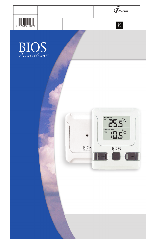
Indoor/Outdoor
Wireless Thermometer
Thermomètre sans l
intérieur/extérieur

2
Project Type
Instructions
Date: September 23 2020
Customer: Thermor Ltd
Job Number: TH0951
Item Number: 261BC
Designer: Alex Vranjesevic
PO: 24735-00
Revision: A
Artwork is not to be amended or scaled. If any changes
are required please send through Thermor oce with
instructions, and we will amend here and resend artwork
through. PLEASE RETURN WITH SIGNATURE
Contact: Graphic’s Department
Colour Breakdown
Reason For Project:
New Item: X
New Branding:
Design Update:
N/A:
UPC (For Reference Only)
Indoor Monitor
Indoor Monitor
Indoor Monitor
Indoor Monitor
A.
B.
C.
D.
2.
1.
3.
4.
7.
5
6.
E.

3
Project Type
Instructions
Date: September 23 2020
Customer: Thermor Ltd
Job Number: TH0951
Item Number: 261BC
Designer: Alex Vranjesevic
PO: 24735-00
Revision: A
Artwork is not to be amended or scaled. If any changes
are required please send through Thermor oce with
instructions, and we will amend here and resend artwork
through. PLEASE RETURN WITH SIGNATURE
Contact: Graphic’s Department
Colour Breakdown
Reason For Project:
New Item: X
New Branding:
Design Update:
N/A:
UPC (For Reference Only)
Indoor/Outdoor
Indoor/Outdoor
Wireless Thermometer
Wireless Thermometer
Instruction Manual
Instruction Manual
Monitor: Remote Sensor:
Monitor: Remote Sensor:
A. Battery Icon E. Transmission Indication LED
A. Battery Icon E. Transmission Indication LED
B. Indoor Temperature
B. Indoor Temperature
C. Signal Detection Icon
C. Signal Detection Icon
D. Outdoor Temperature
D. Outdoor Temperature
1. MAX/MIN Button
1. MAX/MIN Button
2. Clear Button
2. Clear Button
3. ºC/ºF Button
3. ºC/ºF Button
4. Reset Button
4. Reset Button
5. Re-sync Button
5. Re-sync Button
Before You Begin
Before You Begin
1.0 Setup procedure:
1.0 Setup procedure:
1. Insert batteries into the monitor rst.
2. Place the monitor as close as possible next to the remote sensor and insert the
batteries into the remote sensor.
3. Position the monitor and remote sensor within eective transmission range, which
in usual circumstances is 20 to 30 meters (65 to 100 feet). The range is aected
by the building materials and where the monitor and remote sensor are positioned;
try various locations for the best results.
Note:
Note: The remote sensor should be placed in a shaded area for accurate readings.
1.1 Getting Started
1.1 Getting Started
Once the remote sensor has been powered up (or the
RESET
RESET button has been
pressed), the transmission signal is immediately sent to the monitor. The monitor will
attempt to search for the signal for 3 minutes.
Once the signal is received, the dashes (--.-°F) on the monitor will change to the
current outdoor temperature. If after 3 minutes the screen does not change to show
the outdoor temperature, press the
RE-SYNC
RE-SYNC button on the monitor. The monitor will
now attempt to search for the signal for another 3 minutes.
2.0 Troubleshooting
2.0 Troubleshooting
Press the
RESET
RESET button at any time your display shows dashes (--.-°F) and/or ensure
that the remote sensor is in direct line to the monitor.
If the outdoor temperature cannot be received, check:
1. The distance between the monitor or remote sensor should be at least 0.9 to 1.2
meters (3 to 4 feet) away from any interfering sources such as computer
monitors or TV sets.
2. Avoid placing the monitor onto or in the immediate proximity of metal window
frames.
3. Using other electrical products such as headphones or speakers operating on
the same signal frequency (433MHz) may prevent correct signal transmission and
reception.
4. Neighbors using electrical devices operating on the 433MHz signal frequency can
also cause interference.
6. Reset Button
6. Reset Button
7. Test Button
7. Test Button
(not functional)
(not functional)

4
Project Type
Instructions
Date: September 23 2020
Customer: Thermor Ltd
Job Number: TH0951
Item Number: 261BC
Designer: Alex Vranjesevic
PO: 24735-00
Revision: A
Artwork is not to be amended or scaled. If any changes
are required please send through Thermor oce with
instructions, and we will amend here and resend artwork
through. PLEASE RETURN WITH SIGNATURE
Contact: Graphic’s Department
Colour Breakdown
Reason For Project:
New Item: X
New Branding:
Design Update:
N/A:
UPC (For Reference Only)
5. Signals from other household devices, such as doorbells and home security
systems, may temporarily interfere with the units and cause reception failure.
The transmission and reception of temperature reading will resume once the
interference has stopped.
The maximum transmission range is 30 meters (100 feet) from the remote sensor to
the monitor (in open space). However, this depends on the surrounding environment
and interference levels. The temperature signal travels in a straight line from the
remote sensor to the monitor. The signal will not curve around an object. If no
reception is possible, despite the observation of these factors, all units will have to
be reset.
Note:
Note: To reset unit please see 1.0 Setup Procedure.
3.0 Maximum and Minimum Temperature
3.0 Maximum and Minimum Temperature
1. Press the
MAX/MIN
MAX/MIN button once to display the indoor and press again for the
outdoor max/min temperature recorded.
2. To clear the memory, press the
CLEAR
CLEAR button when the max/min temperature is
displayed. It will clear the record of the shown temperature eld.
4.0 ºC/ºF Switchable
4.0 ºC/ºF Switchable
The default measurement for temperature is °F, press the
ºC/ºF
ºC/ºF button to toggle
between °C and °F.
5.0 Signal Detection
5.0 Signal Detection
The signal indicator on the monitor will display the following in the outdoor
temperature window:
6.0 Care of Your Thermometer
6.0 Care of Your Thermometer
• Avoid exposing the thermometer to extreme temperatures, water or severe shock.
• Avoid contact with any corrosive materials such as alcohol, cleaning agents or
perfume.
•
Do not
Do not subject the thermometer to excessive force, shock, dust, temperature or
humidity. Any of these conditions may shorten the life of the thermometer.
•
Do not
Do not tamper with any of the internal components of this thermometer.
This will void the warranty and may cause damage.
No Signal Detected
Signal Detected
Successful Reception

5
Project Type
Instructions
Date: September 23 2020
Customer: Thermor Ltd
Job Number: TH0951
Item Number: 261BC
Designer: Alex Vranjesevic
PO: 24735-00
Revision: A
Artwork is not to be amended or scaled. If any changes
are required please send through Thermor oce with
instructions, and we will amend here and resend artwork
through. PLEASE RETURN WITH SIGNATURE
Contact: Graphic’s Department
Colour Breakdown
Reason For Project:
New Item: X
New Branding:
Design Update:
N/A:
UPC (For Reference Only)
7.0 Specications
7.0 Specications
Temperature Measuring Range
Monitor -50ºC to 70ºC with 0.1ºC resolution
-58ºF to 158ºF with 0.1ºF resolution
Remote Sensor -50ºC to 70ºC with 0.1ºC resolution
-58ºF to 158ºF with 0.1ºF resolution
Temperature Checking Interval
Monitor Every 30 seconds
Remote Sensor Every 30 seconds
Power Source
Monitor 2 x AA batteries, 1.5V batteries
Remote Sensor 2 x AA batteries, 1.5V batteries
(Lithium batteries are recommended
for the winter months)
Battery Life About 12 months
8.0 Remote Sensor
8.0 Remote Sensor
To prevent temperature interference, place the remote sensor away from direct
sunlight, air conditioning, and heater vents. The remote sensor is splash proof
designed, never immerse into water or expose to heavy rain. The remote sensor can
be mounted on a wall or placed on any at surface.
9.0 Monitor
9.0 Monitor
The monitor can be mounted on a wall or placed on any at surface.

6
Project Type
Instructions
Date: September 23 2020
Customer: Thermor Ltd
Job Number: TH0951
Item Number: 261BC
Designer: Alex Vranjesevic
PO: 24735-00
Revision: A
Artwork is not to be amended or scaled. If any changes
are required please send through Thermor oce with
instructions, and we will amend here and resend artwork
through. PLEASE RETURN WITH SIGNATURE
Contact: Graphic’s Department
Colour Breakdown
Reason For Project:
New Item: X
New Branding:
Design Update:
N/A:
UPC (For Reference Only)
10.0 One Year Warranty
10.0 One Year Warranty
The BIOS Weather Indoor/Outdoor Wireless Thermometer has a one year warranty to be
free of manufacturing defects in materials and workmanship under normal applications
for one year of the original owner. If this product becomes inoperable due to defect
and requires repair, return the product with all component pieces and proof of purchase
to the address listed below. This warranty does not cover any shipping/transport
costs. This warranty does not apply if the product is subject to misuse, neglect, rough
handling or damage.
Ship the unit prepaid and insured (at owner’s option) to:
Thermor Ltd.
Attn: Repair Department
16975 Leslie Street
Newmarket, ON L3Y 9A1
www.biosmedical.com
Email: [email protected]
11.0 Industry Canada/FCC Statement
11.0 Industry Canada/FCC Statement
Operation is subject to the following two conditions: (1) this device may not cause
interference, and (2) this device must accept any interference, including interference
that may cause undesired operation of the device.
WARNING:
WARNING: Changes or modications to this unit not expressly approved by the party
responsible for compliance could void the user’s authority to operate the equipment.
NOTE:
NOTE: This equipment has been tested and found to comply with the limits for a Class
B digital device, pursuant to Part 15 of the FCC Rules. These limits are designed to
provide reasonable protection against harmful interference in a residential installation.
This equipment generates, uses and can radiate radio frequency energy and, if not
installed and used in accordance with the instructions, may cause harmful interference
to radio communications.
However, there is no guarantee that interference will not occur in a particular installation.
If this equipment does cause harmful interference to radio or television reception, which
can be determined by turning the equipment o and on, the user is encouraged to try
to correct the interference by one or more of the following measures:
• Reorient or relocate the receiving antenna.
• Increase the separation between the equipment and receiver.
• Connect the equipment into an outlet on a circuit dierent from that to which the
receiver is connected.
• Consult the dealer or an experienced radio/TV technician for help.
Table of contents
Other BIOS WEATHER Thermometer manuals


