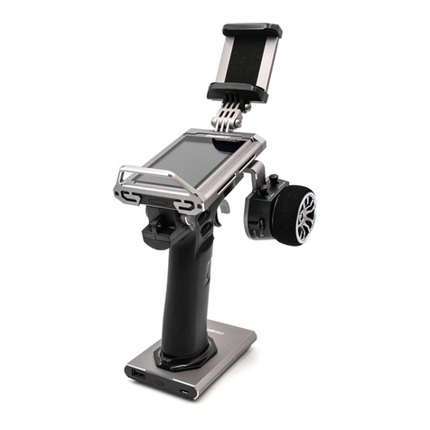
Fly Sky Elysium EL18 User manual

U s e r M a n u a lU s e r M a n u a l
Copyright ©2022 Flysky Technology co., Ltd
Elysium EL18
Website
.
Touching Innity

Thank you for purchasing our products.
Read the manual carefully to ensure your personal safety as well as the safety of your
equipment. If you encounter any problems during using, please refer to this manual rst.
If the problem is still not resolved, please contact the local dealer directly or contact the
customer service sta via the website below:
http://www.ysky-cn.com
The following documents can be downloaded at the ocial Flysky website:
1. EL18 user manual
2. EL18 Quick Start Guide
3. Disclaimer & Warning
Users are advised to read the Disclaimer & Warning rst, then the EL18 Quick Start Guide
and the EL18 user manual.

1.Safety .........................................................................................................5
1.1 Safety Symbols .........................................................................................................................5
1.2 Safety Guide ..............................................................................................................................5
2.Battery Safety Instructions .........................................................................6
3. Product Description ...................................................................................7
3.1 System Features ........................................................................................................................7
3.2 Transmitter Overview ...............................................................................................................8
3.3 Receiver Overview ..................................................................................................................11
3.4 Antenna ..................................................................................................................................11
4.Before Use ................................................................................................12
4.1Transmitter Battery Installation...............................................................................................12
4.2Receiver Installation ................................................................................................................12
4.3 RF Module Adapter Installation ...............................................................................................13
4.4 Left and Right Gimbal Swap ....................................................................................................13
5. Operation Guide ......................................................................................15
5.1 Basic Setting Guidelines..........................................................................................................15
5.2 Language Selection .................................................................................................................15
5.3 Power On ................................................................................................................................16
5.4Binding ....................................................................................................................................16
5.5 Power O ................................................................................................................................17
5.6 Neck Strap Hook and SD Card Slot ..........................................................................................17
5.7 Warning After Turning On ........................................................................................................17
5.8 Upgrading RF Firmware ..........................................................................................................18
5.9 Upgrading Transmitter Firmware ............................................................................................19
6. Radio Interface .........................................................................................20
7. Function Settings .....................................................................................21
7.1 Select Model ...........................................................................................................................21
7.1.1 Create A Model .................................................................................................................................. 21
7.1.2 Create New Label .............................................................................................................................. 21
7.2 Channel Monitor .....................................................................................................................21
7.3 Model Settings ........................................................................................................................22
7.3.1 Model Name ...................................................................................................................................... 22
7.3.2 Model Image ...................................................................................................................................... 22
7.3.3 Use Global Function ......................................................................................................................... 22
7.3.4 ADC Filter .......................................................................................................................................... 22
7.3.5 Internal RF ........................................................................................................................................ 22
7.3.7 Trainer ............................................................................................................................................... 24
7.3.8 Timer1 ............................................................................................................................................... 24
7.3.6 External RF ........................................................................................................................................ 24
7.3.9 Timer2 ............................................................................................................................................... 26
7.3.10 Timer3 ............................................................................................................................................. 26
7.3.11 Preight Checks .............................................................................................................................. 26
7.3.12 Trims ............................................................................................................................................... 27
Table of Contents

7.3.13 Throttle ...........................................................................................................................................27
7.3.14 HELI Setup ....................................................................................................................................... 28
7.3.15 Flight Modes .................................................................................................................................... 28
7.3.16 Inputs .............................................................................................................................................. 28
7.3.17 Mixes ............................................................................................................................................... 30
7.3.18 Outputs ........................................................................................................................................... 32
7.3.19 Curves .............................................................................................................................................33
7.3.20 Global Variables .............................................................................................................................. 34
7.3.21 Logical Switches .............................................................................................................................. 34
7.3.22 Special Functions ............................................................................................................................35
7.3.23 Telemetry ........................................................................................................................................ 36
7.4 Radio Settings .........................................................................................................................37
7.4.1 Tools .................................................................................................................................................. 37
7.4.2 SD-HC Card ........................................................................................................................................ 37
7.4.3 Radio Setup ....................................................................................................................................... 38
7.4.4 Themes ............................................................................................................................................. 40
7.4.5 Global Functions ...............................................................................................................................40
7.4.6 Trainer ............................................................................................................................................... 40
7.4.7 Hardware .......................................................................................................................................... 41
7.4.8 Version .............................................................................................................................................. 42
7.5 Screen Settings .......................................................................................................................43
7.6 Reset .......................................................................................................................................43
7.7 Statistics .................................................................................................................................44
7.8 About EdgeTX ..........................................................................................................................44
8.Product Specications .............................................................................45
8.1 Transmitter Specications ......................................................................................................45
9. Package Contents ....................................................................................46
10.Certications ..........................................................................................47
10.1 DoC .......................................................................................................................................47
10.2 CE Warning ............................................................................................................................47
10.3 FCC Statement ......................................................................................................................47
10.4 Environmentally friendly disposal ........................................................................................48
10.5 UKCA Compliance Statement ................................................................................................48

1.Safety
Warning • Not following these instructions may lead to major injuries.
Danger • Not following these instructions may lead to serious injuries or death.
Attention • Not following these instructions may lead to minor injuries.
• Misuse of this product may lead to serious injury or death. To ensure the safety of you
and your equipment, read this manual and follow the instructions.
• Make sure the product is properly installed in your model. Failure to do so may result in
serious injury.
• Make sure to disconnect the receiver battery before turning o the transmitter. Failure to
do so may lead to unintended operation and cause an accident.
• Ensure that all motors operate in the correct direction. If not, adjust the direction rst.
• Make sure the model ies within a certain distance. Otherwise, it would cause loss of
control.
• Do not use the product at night or in bad weather like rain or thunderstorm. It can cause
erratic operation or loss of control.
• Do not use the product when visibility is limited.
• Do not use the product on rain or snow days. Any exposure to moisture (water or snow)
may cause erratic operation or loss of control.
• Interference may cause loss of control. To ensure the safety of you and others, do not
operate in the following places:
Near any site where other radio control activity may occur
Near power lines or communication broadcasting antennas
Near people or roads
On any body of water when passenger boats are present
• Do not use this product when you are tired, uncomfortable, or under the inuence of
alcohol or drugs. Doing so may cause serious injury to yourself or others.
• The 2.4GHz radio band is limited to line of sight. Always keep your model in sight as a
large object can block the RF signal and lead to loss of control.
• Never grip the transmitter antenna during operation. It signicantly degrades signal
quality and strength and may cause loss of control.
• Do not touch any part of the model that may generate heat during operation, or
immediately after use. The engine, motor or speed control, may be very hot and can
cause serious burns.
• The EL18 system uses EdgeTX open source rmware. Ocial updates will be posted on
our ocial website from time to time. If you modify or use unocial software, the system
may encounter out-of-control or error. Our company will not accept legal responsibility
caused by unocial software!
Pay close attention to the following symbols and their meanings. Failure to follow these warnings could cause damage,
injury or death.
1.1 Safety Symbols
1.2 Safety Guide

2.Battery Safety Instructions
The battery should be stored in a location that is not accessible to infants and toddlers.
Be sure to charge the battery before ying.
• If a battery leak accidentally comes in contact with skin, clothing, etc., wash it immediately with
water. If it comes in contact with eyes wash immedietly. Seek medical attention if necessary.
When not in use for a long time, remove the battery from the transmitter and store it in a dry
environment.
Do not throw used batteries into the garbage can, etc., and dispose of them according to the
treatment methods specied in each area.
Use only the battery specied by the manufacturer.
Take care to prevent the battery from falling, bumping or vibrating.
If the battery is damaged, stop using it immediately.
Do not use batteries that are damaged, aged or have abnormalities such as leaks.
Do not short circuit the battery.
Do not repair, modify, dissaemble, crush or punture the battery.
Do not allow contact with water.
Do not charge or store the battery in high temperatures or in direct sun light.
Store the battery in a cool, dry environment.
Do not charge under the following conditions:
• Covered or without ventalation.
• In extremely cold or hot conditions.
Do not use around ammable gases or liquids.
Do not bend, stretch or pull on the power cord.
• The power cord may be damaged by re, heat, electric shock etc.

Website
7
3. Product Description
The Elysium, referred to as EL18, is a transmitter using EdgeTX system with a 3.5in IPS color touch-screen. The EL18 has 2
RF options, internal RF and external RF. the internal RF, namely AFHDS 3 supports up to 18 channels of output, the external
RF supports up to 32 channels of output. The system comes with the Tmr receiver, making it a perfect system for FPV.
3.1 System Features
AFHDS 3
EdgeTX
AFHDS 3 (third-generation automatic frequency hopping digital system) is a newly developed digital wireless system with
independent intellectual property rights by FLYSKY. It is compatible with one-way and two-way real-time data packet
transmission and transparent data stream transmission.In other words, this system has advantages of both AFHDS 2A and
WS2A wireless system. It equips with a brand-new 2.4G chip, stable and reliable connection, good real-time performance,
and supports various congurations. Bring you the optimal conguration for multi-scenario application performance.
EdgeTX is an open source operating system for transmitter. EdgeTX is very powerful. Users can congure the transmitter
according to their own needs, making transmitter more comprehensive and higher performance.
Compatible with
One-way/two-way
Real-time Data
Transmission
The system supports one-way and two-way connections. When the transmitter is working in one-
way transmission way, the receiver can receive data from the transmitter. When the transmitter
is working in two-way transmission way. The receiver can receive data from the transmitter and
the transmitter can also receive data from the receiver, as well as the information cross from the
temperature and speed sensor modules.
Data Transparent
Transmission
The independent data transparent transmission module is built into RF system, which can
realize data transmission via transmitter and transparent transmission. It can be used for data
transmission of ight control.
Intelligent RF
Conguration
To set the parameters which aect RF transmission distance, speed and anti-interference, such
as numbers of channels, resolution, bandwidth and receiver sensitivity. The system can be set
according to dierent application requirements to obtain the most suitable performance.
Multi-channel
Frequency
Hopping
This systems bandwidth ranges from 2.402GHz to 2.480GHz. Set intelligent RF congurations
accordding to your required, it can avoid or reduce the interference from other transmitters with
the same frequency via dierent congurations, dierent time of powering on the transmitter,
various patterns to the hopping frequency and various using frequency spots.
Unique ID
Recognition
System
Each transmitter and receiver has it's own unique ID. Once the transmitter and receiver have been
bound, they will save the each other's ID and only connect with each other. When the syetem is
working,if the IDs are matched with each other, then the connection will be connected, otherwise,
there is no connection between transmitter and receiver. This unique ID recognition syetem resists
the interference so as to make the system stabler and more reliable.
Low Power
Consumption
It is built using highly sensitive, low power consumption components. And it works in the way of
interval data transmission to improve transmitting ecient eectively and extend the working time
of the battery distinctly, while it consumes as little as one tenth the power of a standard FM system.

Website
8
Elysium EL18
3.2 Transmitter Overview
Front View
[1] Type-C USB Port [10] Battery Compartment Covers
[2] VRA [11] Trainer Port
[3] Switch B [12] VRB
[4] Switch A [13] Switch C
[5] TRIM [14] Switch D
[6] Left Stick [15] TRIM
[7] Grip [16] Right Stick
[8] Power Switches [17] Touch-screen
[9] Neck Strap Hook [18] SD Card Slot
<>

Website
9
Back View
[19] Speaker [25] DFU Button
[20] Switch G [26] Screw Holes for Fixing Neck Strap Hook
[21] Switch H [27] Switch F
[22] RF Firmware Forced-update Button [28] Switch E
[23] Type-C Connection Toggling Button [29] Stealth I/O RF Module Interface
[24] Screw Holes for Fixing RF Module Adapter [30] Rotatable Antenna
<>
<>
Type-C USB Port: For charging, simulator or update.
VRA: Knob
VRB: Knob
Switch A: Short 2 position switch
Switch B: Short 3 position switch
Switch C: Short 2 position automatic return switch
Switch D: Short 2 position switch
Switch E: Long 2 position automatic return switch
Switch F: Short 3 position switch
Switch G: Short 3 position switch
Switch H: Long 2 position automatic return switch
TRIM(Left)/TRIM(Right): Trim for aileron , elevator, throttle and rudder
Left Stick:Non self-centering
Right Stick:Self-centering
Trainer Port:For trainer function
RF Firmware Forced-update Button: For forced updating the RF module rmware
Type-C Connection Switch Button: For switching the Type-C to connect the transmitter MCU or RF module MCU
DFU button: To update the transmitter rmware
Stealth I/O: To connect to the external RF module
Antenna:Omnidirectional antenna, foldable
Switches/Buttons/Ports

Website
10
Elysium EL18
DFU Button
The DFU button is located in in the screw hole marked in the green circle in the picture below. The DFU button is used to
update the EL18 rmware.
Note: Do not operate the DFU button with sharp or metal objects to prevent damage to its internal structure.
For the steps on use (To be updated...)
Type-C Connection Toggling Button
To toggle the Type-C connection to RF MCU or the transmitter MCU. When the RF rmware needs to be focred upgraded,
press this button to toggle the Type-C connection to RF MCU rst.
Note: By default, the Type-C connects to the transmitter MCU.
DFU Button
Type-C Connection Toggling Button
SD Card Slot

Website
11
3.3 Receiver Overview
N.Port
VCC
GND
Bind Button
Antennas
LED
3.4 Antenna
Attention To ensure signal quality, the antenna should be perpendicular to the model body.
Warning Do not hold the antenna during use in order to prevent signal quality loss.
Attention Do not pull or bend the antenna.
夹角
Strong Signal Strong Signal
Weak Signal

Website
12
Elysium EL18
4.1Transmitter Battery Installation
4.2Receiver Installation
4.Before Use
Before operation, please follow the instructions in this chapter to install the battery and connect the device.
Danger • Use only the battery specied by the manufacturer.
Danger • Do not open, disassemble, or repair the battery yourself.
Danger • Do not squeeze, puncture, or touch the metal terminals of the battery.
Danger • Do not expose the battery to high temperatures or liquids.
Danger • Take care to prevent the battery from dropping, bumping or vibrating.
Danger • Store the battery in a dry, cool environment.
Danger • If the battery is damaged, stop using it immediately.
1. Unscrew both battery compartment covers from the transmitter handles.
2. Insert 2 18650 batteries into the battery compartments respectively.
• Please pay attention to the anode and cathode of the battery, refer to
the digram for correct installation.
• Use two batteries to ensure the power supply capacity of the battery.
3. Screw the battery compartment covers back into place.
Make sure that the receiver is mounted in an appropriate location within the model, to ensure a stable signal, maximum
range and to mitigate external interference, follow these guidelines:
Pay attention to the following when installing the receiver:
1. Make sure the receiver is not installed near ESCs or other sources of electrical noise.
2. Keep the receiver's antennas away from conductive materials such as carbon or metal. To ensure normal function
make sure there is a gap of at least 1cm between the antenna and the conductive material.
3. Make sure that the two antennas of the receiver are xed at 90 degrees to each other (as shown below).
Attention • Do not connect the receiver to the power supply during these steps to avoid damage.

Website
13
4.3 RF Module Adapter Installation
Two RF module adapters are included with the transmitter to match dierent RF module. To install the suitable RF
module adapter according to the actual RF module.
The EL18 is able to switch stick functions as needed. When the EL18 is shipped from the factory the left stick is set up for
throttle with non self-centering. Follow the steps below to set right stick to non self-centering if the right stick is going to
set up for throttle.
Follow the steps below to install
the RF adapter.
1. There are 4 screw holes and
one port at the back of the
transmitter, shown as below.
The screw holes are used to
x the RF module adapter to
the transmitter and the port is
used to connect the interface
of the RF module adapter.
2. Align the holes of the RF
module adapter up to the
holes on the transmitter, and
make sure the interface of the
RF module adapter insert the
port entirely, then tighten the
screws.
FGPZ04 adapter FGPZ05 adapter
4.4 Left and Right Gimbal Swap
1. Remove the 2 hand grips and switch pads, then
remove all 10 screws on the bottom of the transmitter
apart from the screws in the nger grips. Lift gently to
pull the cover apart.
2. Left and right gimbals shown below for clarity.
Left
Right
Pad
Square hole
Attention
Don't pull the front cover and
back cover too far apart to avoid
damaging cables.
Do not
remove this
screw Pull
the
back
cover
gently
Pry
open
RX
GND
VCC
S.port
PPM/TX

Website
14
Elysium EL18
3. Take out the assembly and loosen the screws
marked in the gure.
4. As shown, attach the assembly, removed from the
left assembly to the right assembly, and tighten the
screws marked in the gure.
5. Replace the back of the transmitter and tighten the
screws, then replace the grips.
Left
Loosen
Right
Assembly
Tighten
Left
Right
Assembly

Website
15
5.2 Language Selection
5.1 Basic Setting Guidelines
5. Operation Guide
After the preparation is complete, you can follow the instructions in this chapter to get started.
If you use the open-source system for the rst time, you can set up the transmitter according to the following basic setting
guidelines:
Language Selection → Mode Selection → Stick Mode → Assign Channel → Stick Calibration → Bind → Protocol Setting →
Failsafe.
• Language Selection: Refer to "5.2 Language Selection".
• Model Selection: Refer to "7.1 Select Model".
• Stick Mode: Select the appropriate stick mode according to your habit. Refer to "7.4.3 Radio Setup → Default Channel
Order and Mode".
• Assign Channel: Set the channel-related functions. Refer to "7.3.16 Inputs and 7.3.17 Mixes".
• Stick Calibration: Refer to "7.4.7 Hardware → Inputs → Calibration".
• Bind: Bind the transmitter with the receiver. Refer to "7.3.5 Internal RF → Bind"
• Protocol Setting: Set the output signal type of the receiver interface. Refer to "7.3.5 Internal RF → Type → Modules
Option".
• Failsafe: Set the failsafe. Refer to "7.3.5 Internal RF → Failsafe Mode".
By default, the transmitter is installed with one language. If you need to change the language, you need to update
the firmware. To change Chinese to English, update the Chinese firmware to English firmware. Refer to "5.9 Updating
Transmitter Firmware"

Website
16
Elysium EL18
5.3 Power On
5.4Binding
Follow the steps below to turn on the transmitter:
1. Make sure all the switches are at their highest positions and the
throttle is at its lowest position.
2. Press and hold both of the Power Switches until the screen turns on.
Warning • The system is now active, please use extreme caution during use.
Warning • For your safety, make sure the throttle is at its lowest position and switches at their
highest.
1. Enter the "Model Setttings" menu, then select "Internal RF" to enter the submenu. After setting the corresponding mode,
ie FLYSKY AFHDS 3, suitable type(Classic 18ch, Classic 10ch, Routine 18ch, Fast 8ch or Lora 12ch) and Moudule options(
output signal type of receiver), tap the "Bind" to put the transmitter into bind state.
2. Press and hold the receiver Bind button while powering on the receiver, release the BIND button after receiver is
powered on or powering on the receiver rst, then press and hold the Bind button for 3 seconds, the LED of the receiver
will ash rapidly, indicating the receiver is in bind mode;
3. The binding process is nished when the LED of the receiver is solid on.
4. Check to make sure the transmitter and the receiver functions are working correctly, repeat steps 1 to 3 (binding process)
if any problems arise.
Note: For one-way mode,after the receiver LED becomes slow ashing, then put the transmitter to exit the binding
state. At this time, the receiver LED is solid on, indicating that the binding is successful.
TMr receiver supports binding in two-way, follow the steps below to nish.
These steps only apply to the Elysium and it's included receivers. For other receivers please refer to their user
manual.
As the product is constantly updated, please visit the FLYSKY website for the latest transmitter and receiver
compatibility documents.
Danger • When in use make sure not to y beyond the maximum range.
Attention • External signal sources may aect signal quality.
Danger • Check each channel is working correctly before use to avoid any unexpected accidents.

Website
17
Danger • For safety always power o the receiver before the transmitter.
5.6 Neck Strap Hook and SD Card Slot
To access the card slot, need to remove the Neck Strap Hook rst.
The steps are as below:
1. loosen the two hex screws on the back Neck strap hook.
2. Remove the Neck strap hook to expose the SD card slot.
3. Press the SD card inwards and release to remove. SD card slot
Note: The EL18 transmitter needs to have an SD card installed for
the rmware to work correctly.
5.5 Power O
5.7 Warning After Turning On
Follow the steps below to turn o the transmitter:
1. Turn o the receiver.
2. Press and hold both Power Switches until the screen turns o.
Press and hold the Power Switches to turn on the transmitter. Before entering the radio interface, the system will check
the position of the throttle stick and controls, as well as other starting conditions. There will be a corresponding error
warning which needs to be cleared by user operation or skipped by pressing any key, when the conditions do not match.
If the throttle stick is not in the lowest position when
turning on, this warning will appear. Then put the throttle
stick to the lowest position or press any key to skip.
This is a warning that the controls are not in their default
position. ↑ is the default position.
Throttle Warning Control Warning

Website
18
Elysium EL18
5.8 Upgrading RF Firmware
Type-C Connection Toggling Button
RF Firmware Forced-update Button
The RF module rmeware of EL18 can be
updated. Follow the steps below to upgrade.
1. Download the latest version rmware at PC
side, then open it.
2. Use USB cable to connect the transmitter and
the receiver, then select "USB Storage(SD)".
3. Press Type-C Connection Toggling Button to
toggle the Type-C connection to RF module
MCU, meanwhile the RF LED will light up.
4. At PC side, click Upadte to start the updating.
It can upgrade the RF module rmware in forced
update mode. Follow the steps belllow to update.
1. Download the latest rmware at PC side, then
open it.
2. Use USB cable to connect the transmitter and
the receiver, then select "USB Storage(SD)".
3. Press Type-C Connection Toggling Button to
toggle the Type-C connection to RF module
MCU, meanwhile the RF LED will light up.
4. Press RF Firmware Forced-update Button to
enter force-update mode.
5. At PC side, click Upadte to start the updating.

Website
19
Follow the steps below to update the
rmware of the transmitter:
1. Download the latest version rmware at
PC side.
2. Use USB cable to connect the
transmitter and the receiver, then select
"USB Storage(SD)".
3. Copy the rmware downloaded to
FIRMWARE folder of "SD-HC Card".
4. Upplug the USB cable, then turn o the
transmitter.
5. According to the directions as shown,
push both TRIM buttons at the same
time while pressing the both Power
Switches for 2S, then release them, at
the time, the transmitter screen lights
up. The transmitter enters rmware
updating state, as shown in Pic 1.
6. Press R TRIM button to access the
"FIRMWARE" folder, then push upwards
or downwards to select the rmware
you desired,as shown in Pic 2.
7. Press and hold the R TRIM button for a
while to start the update. The progress
bar will appear on the sreen, as shown
in Pic 3.
8. Press L TRIM button to return after the
progress has been nished, as shown in
Pic4. Push R TRIM button downwards to
select "Exit", then exit the update state
by pressing R TRIM button
5.9 Upgrading Transmitter Firmware
Pic 1
Pic 3
Pic 2
Pic 4

Website
20
Elysium EL18
The main interface includes the function icons, such as Select Model,Channel Monitor, Model Settings, Screens Settings,
Reset Telemetry, Statistics and About EdgeTX.
6. Radio Interface
This is an introduction about the transmitter's main interface.
Signal Strength
Date
Time
Volume Level
Transmitter Battery
Right Trim
VRB Knob
Left Trim
Click here to display
function icons.
VRA Knob
Table of contents
Other Fly Sky Controllers manuals
