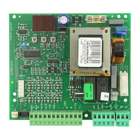
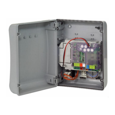
FAAC E124 User manual

E124
Translation of the original instructions

FAAC S.p.A. Soc. Unipersonale
Via Calari, 10 - 40069 Zola Predosa BOLOGNA - ITALY
Tel. +39 051 61724 - Fax +39 051 09 57 820
www.faac.it - www.faacgroup.com
© Copyright FAAC S.p.A. from 2020. All rights reserved.
No part of this manual may be reproduced, archived, distributed to third
parties nor copied in any other way, in any format and with any means,
be it electronic, mechanical or by photocopying, without prior written
authorisation by FAAC S.p.A.
All names and trademarks mentioned are the property of their respective
manufacturers.
Customers may make copies exclusively for their own use.
This manual was published in 2020.
© Copyright FAAC S.p.A. del 2020. Todos los derechos están reservados.
No puede reproducirse, archivarse, distribuirse a terceros ni copiarse de
ningún modo, ninguna parte de este manual, con medios mecánicos o
mediante fotocopia, sin el permiso previo por escrito de FAAC S.p.A.
Todos los nombre y las marcas citadas son de propiedad de los respectivos
fabricantes.
Los clientes pueden realizar copias para su uso exclusivo.
Este manual se ha publicado en 2020.
© Copyright FAAC S.p.A. van 2020. Alle rechten voorbehouden.
Niets uit deze handleiding mag gereproduceerd, gearchiveerd, aan derden
openbaar gemaakt of op andere wijze gekopieerd worden, in om het even
welke vorm en met geen enkel middel, noch elektronisch, mechanisch of
via fotokopiëren, zonder schrfitelijke toestemming vooraf van FAAC S.p.A.
Alle vermelde namen en merken zijn eigendom van de respectievelijke
fabrikanten.
Deklantenmogenkopieënmakendieenkelvooreigengebruikbestemdzijn.
Dez handleiding werd in 2020 gepubliceerd.
© Copyright FAAC S.p.A. ab dem 2020. Alle Rechte vorbehalten.
KeinTeildieses Handbuchsdarfreproduziert,gespeichert,an Dritteweiter-
gegeben oder sonst auf eine beliebige Art in einem beliebigen Format und
mitbeliebigenMittelnkopiertwerden,wedermitelektronischen,nochme-
chanischenoderdurchFotokopieren,ohnedieGenehmigungvonFAACS.p.A.
AlleerwähntenNamenundMarkensindEigentumderjeweiligenHersteller.
Die Kunden dürfen nur für den Eigengebrauch Kopien anfertigen.
Dieses Handbuch wurde 2020 veröffentlicht.
© Copyright FAAC S.p.A. depuis 2020. Tous droits réservés.
Aucunepartie dece manuel ne peutêtre reproduite, archivéeoudistribuée
à des tiers ni copiée, sous tout format et avec tout moyen, qu’il soit électro-
nique, mécanique ou par photocopie, sans le consentement écrit préalable
de FAAC S.p.A.
Tous les noms et les marques cités sont la propriété de leurs fabricants
respectifs.
Les clients peuvent faire des copies pour leur usage exclusif.
Ce manuel a été publié en 2020.
© Copyright FAAC S.p.A. dal 2020. Tutti i diritti riservati.
Nessunapartediquestomanualepuòessereriprodotta,archiviata,distribuita
a terzi né altrimenti copiata, in qualsiasi formato e con qualsiasi mezzo, sia
essoelettronico,meccanicootramitefotocopia,senzailpreventivoconsenso
scritto di FAAC S.p.A.
Tutti i nomi e i marchi citati sono di proprietà dei rispettivi fabbricanti.
I clienti possono effettuare copie per esclusivo utilizzo proprio.
Questo manuale è stato pubblicato nel 2020.

E124 1 532365 - Rev.A
Translation of the original instructions ENGLISH
CONTENTS
EU Declaration of conformity ........................... 2
1. INTRODUCTION TO THE INSTRUCTION MANUAL ...... 2
Meaning of the symbols used ........................... 3
2. SAFETY RECOMMENDATIONS ......................... 4
Installer safety......................................... 4
Transport and storage.................................. 4
Disposalof the product................................. 4
3. E124................................................... 5
3.1 Intended use......................................... 5
3.2 Limitations of use .................................... 5
3.3 Unauthorised use .................................... 5
3.4 Product identification................................. 5
3.5 Technical characteristics .............................. 6
4. INSTALLATION REQUIREMENTS....................... 7
Electrical system ....................................... 7
Overall dimensions of the enclosure..................... 7
5. INSTALLATION ........................................ 8
Tools required ......................................... 8
5.1 Install the enclosure .................................. 8
Remove the cover ...................................... 8
Preparethe cable routing holes......................... 8
Fasten the enclosure ................................... 9
Install the cover........................................ 9
5.2 Components ........................................ 10
Switching power supply ............................... 10
Board E124 ........................................... 11
5.3 Connections ........................................ 12
BUS 2easy (2EASY) devices............................. 12
Control devices (IN) ................................... 12
Limitswitch (FC)...................................... 12
Gatecoder (ENC)....................................... 13
Configurable outputs (OUT1, OUT2) .................... 13
Flashing light 24 V
"
(LAMP).......................... 13
Electric lock (LOCK/ OUT1, OUT2) ....................... 13
Motor 1 (MOT1) ....................................... 13
Motor 2 (MOT2) ....................................... 13
XF MODULE ........................................... 14
Radio receiver/decoder board.......................... 14
Emergency batteries (BATTERY)........................ 14
Mains power supply (CON)............................. 14
6. START-UP ............................................15
Set-upprocedure ..................................... 15
6.1 Turn power on to the board .......................... 15
6.2 Programming the board ............................. 15
6.3 SETUP .............................................. 21
6.4 Configuring movements and timing .................. 22
6.5 Adjusting the anti-crushing system................... 22
6.6 Final checks......................................... 23
6.7 Close the enclosure.................................. 23
7. ACCESSORIES.........................................24
7.1 BUS 2easy devices................................... 24
BUS 2easy control devices ............................. 24
BUS 2easy Photocells, Sensitive edges .................. 25
BUS 2easy encoder .................................... 26
7.2 Registering/Removing BUS 2easy devices ............. 26
7.3 Relay photocells..................................... 27
Functional test (Fail-Safe) ............................. 27
7.4 Radio controls - SLH/SLHLR .......................... 28
Memorising the master on the board................... 28
Adding radio controls ................................. 28
7.5 Radio controls - RC/LC ............................... 29
Memorising the radio controls on the board ............ 29
Adding radio controls ................................. 29
7.6 Radio controls - DS .................................. 30
Memorising radio controls on the board ................ 30
7.7 Deleting all radio controls............................ 30
7.8 Simply Connect ..................................... 31
7.9 Emergency batteries................................. 32
7.10 External power supply.............................. 32
8. DIAGNOSTICS ........................................33
Signalling LEDS on the board .......................... 33
Firmware version (FW) ................................ 34
Status of the automation .............................. 34
Checking the movement............................... 34
BUS 2easy status ...................................... 34
Warnings from a programmable output ................ 34
Error codes, Alarms/Info............................... 35
RESET ................................................ 36
9. MAINTENANCE.......................................37
9.1 Routine maintenance................................ 37
Cycle counter ......................................... 38
Maintenance requested ............................... 38
9.2 Restoring factory settings............................ 38
10. OPERATION .........................................39
Commands ........................................... 39
Battery operation (if present).......................... 39
Detection devices ..................................... 39
Accessories ........................................... 39
Operating logics ...................................... 39
TABLES
1 Technical data ................................................................ 6
2 Basic programming menu.............................................16
3 Advanced programming menu......................................18
4 SETUP phases ...............................................................21
5 BUS 2easy command DIP switches................................24
6 BUS 2easy photocells and sensitive edges DIP switches 25
7 Automated system status..............................................34
8 Errors, Alarms, Info........................................................35
9 Scheduled maintenance................................................37

E124 2 532365 - Rev.A
Translation of the original instructions ENGLISH
1. INTRODUCTION TO THE INSTRUCTION MANUAL
This manual provides the correct procedures and
requirements for installing E124 and maintaining it
in a safe condition.
When drafting the manual, the results of the risk
assessment conducted by FAAC S.p.A. on the entire
product life cycle have been taken into account in
orderto implementeffectiverisk reduction measures.
The following stages of the life cycle of the product
have been considered:
-Delivery/handling
-Assembly and installation
-Set-up and commissioning
-Operation
-Maintenance/troubleshooting
-Disposal at the end of the product’s life cycle
Risks arising from installation and using the product
have been taken into consideration; these include:
-Risks for the installation/maintenance technician
(technical personnel)
-Risks for the user of the automation system
-Risks to product integrity (damage)
InEurope, the automationof agate fallsunderthe Ma-
chinery Directive 2006/42/EC and the corresponding
harmonised standards. Anyone automating a gate
(neworexisting)isclassified asthe Manufacturerof the
Machine. They are therefore required by law, among
otherthings, tocarry outa risk analysis of themachine
(automatic gate in its entirety) and take protective
measures to fulfil the essential safety requirements
specified in Annex I of the Machinery Directive.
FAAC S.p.A. recommends that you always comply
with the EN 12453 standard and in particular that you
adoptthe safetycriteria anddevices indicated,without
exception, including the dead-man function.
This manual also contains general information and
guidelines,whichare purelyillustrativeand notexhau-
stive, in order to facilitate the activities carried out by
the Manufacturer of the Machine in all respects with
regardtocarryingout therisk analysis anddraftingthe
instructions foruseand maintenanceofthe machine.It
shouldbeclearlyunderstood that FAAC S.p.A.accepts
no liability for the reliability and/ or completeness of
the above instructions. As such, the manufacturer of
the machine must carry out all the activities required
by the Machinery Directive and the corresponding
harmonised standards on the basis of the actual
condition of the locations and structures where the
productE124 will be installed,prior to commissioning
themachine.These activities include the analysis ofall
therisks associated withthe machine and subsequent
implementation of all safety measures intended to
fulfil the essential safety requirements.
This manual contains references to European stan-
dards. The automation of a gate must fully comply
withany laws,standardsand regulationsapplicablein
the country where installation will take place.
LUnlessotherwisespecified,themeasurementsprovided
in the instructions are in mm.
EU DECLARATION OF CONFORMITY
The Manufacturer
Company name: FAAC S.p.A. Soc. Unipersonale
Address: Via Calari, 10 - 40069 Zola Predosa BOLOGNA - ITALY
hereby declares under its own exclusive liability that the following product:
Description: Electronic equipment
Model: E124
complies with the following applicable EU legislations:
2014/30/EU, 2014/35/EU, 2011/65/EU
Furthermore, the following harmonised standards have been applied:
EN 61000-6-2:2005, EN 61000-6-3:2007+A1:2011
EN 60335-1:2012+A11:2014+A13:2017, EN 60335-2-103:2015
Other standards applied: EN 13849-1:2015 CAT.2 PL“C”, EN 13849-2:2012
Bologna, 01-08-2020 CEO
A. Marcellan

E124 3 532365 - Rev.A
Translation of the original instructions ENGLISH
PERSONAL PROTECTIVE EQUIPMENT
Obligation to wear work gloves.
Obligation to wear safety footwear.
MARKINGS ON PACKAGING
Handle with care. Presence of fragile parts.
This way up: DO NOT turn over.
Store away from water and humidity.
CE marking.
RECYCLE and DISPOSE of at authorised waste collection
centres.
TOOLS (type and size)
6-8...
FLAT-HEAD SCREWDRIVER of the specified size (6, 8...)
6-8...
CROSS-HEAD SCREWDRIVER of the specified size (6, 8...)
ELECTRICIAN'S SCISSORS
WIRE STRIPPERS
MEANING OF THE SYMBOLS USED
NOTES ANDWARNINGS INTHE INSTRUCTIONS
FWARNING ELECTRIC SHOCK HAZARD - The operation or
stepdescribedmustbecarriedoutfollowingtheinstruc-
tions provided and according to the safety regulations.
!WARNING, personal injury hazard or risk of damage to
components - The operation or stage described must
be performed following the supplied instructions and
applicable safety regulations
LWARNING - Details and specifications which must be
respected in order to ensure that the system operates
correctly.
RECYCLINGANDDISPOSAL-Thematerialsusedinmanu-
facturing, the batteries and any electronic components
must not be sent to landfill. They must be taken to
authorised recycling and disposal centres.
FIGURE E.g.: 1-3 see Figure 1 - item 3.
TABLE E.g.: 1 seeTable 1.
§ CHAPTER/SECTION E.g. §1.1 see Section 1.1.
LED off
LED on
LED flashing
LED flashing quickly
SAFETY SIGNS AND SYMBOLS (EN ISO 7010)
GENERAL HAZARD Risk of personal injury or damage
to the parts.
RISK OF ELECTRIC SHOCK Risk of electric shock from
live parts.
SPENT BATTERY HAZARD Risk to the environment and
health posed by batteries at the end of their lives due to
fluid escaping.
EXPLOSION HAZARD Risk of explosion due to gas pro-
duced by lead batteries building up inside the container
(OPTIONAL).

E124 4 532365 - Rev.A
Translation of the original instructions ENGLISH
2. SAFETY RECOMMENDATIONS
INSTALLER SAFETY
TRANSPORT AND STORAGE
DISPOSAL OF THE PRODUCT
!Thepackagingmaterials(plastic, polystyreneetc.)must
notbeleftwithin reach of childrenas they are potential
sources of danger.
Discard the packaging after use in the appropriate con-
tainers in compliance with waste disposal regulations.
Installation activities require special work conditions
to reduce to the minimum the risks of accidents and
serious damage. Furthermore, the suitable precau-
tionsmust betaken topreventrisksof injurytopersons
or damage.
!Theinstallermust beingoodphysicaland mentalcondi-
tion, aware of and responsible for the hazards that may
be generated when using the product.
The work area must be kept tidy and must not be left
unattended.
Do not wear clothes or accessories (scarves, bracelets,
etc.) that may get caught in moving parts.
Always wear the personal protective equipment recom-
mended for the type of activity to be carried out.
The required level of workplace lighting must be equal
to at least 200 lux.
OperateCE markedmachineryand equipmentincompli-
Store the product in its original packaging, in closed
and dry premises, protected from the sun and free
from dust and aggressive substances. Protect from
mechanicalstress. If storedfor morethan 3 months,
regularly check the condition of the components and
the packaging.
-Storage temperature: 5°C to 30°C.
-Percentage of humidity: 30% to 70%.
This product has been placed on the market as a
controlsystemfor actuatorsforswinging gates,there-
fore must not be commissioned until the machine in
which it has been incorporated has been identified
and declared to conform to the Machinery Directive
2006/42/EC by the actual Manufacturer.
!Incorrect installation and/or incorrect use of the prod-
uct might cause serious harm to people. Read and
comply with all the instructions before starting any
activity on the product. Keep these instructions for
future reference.
Performinstallationand otheractivitiesadheringtothe
sequences provided in the instructions manual.
Always comply with all the requirements contained in
the instructions and warning tables at the beginning
of the paragraphs. Always comply with the safety
recommendations.
Only the installer and/or maintenance technician is au-
thorised to work on the automation components. Do
not modify the original components in any way.
Close off the work site (even temporarily) and prevent
access/transit. EC countries must comply with the
legislation that transposes the European Construction
Site Directive 92/57/EC.
The installer is responsible for the installation/testing
of the automation and for completing the Register of
the system.
Theinstallermustproveordeclaretopossess technical
and professional proficiency to perform installation,
testing and maintenance activities according to the
requirements in these instructions.
ance with the manufacturer's instructions. Use work
instruments in good conditions.
Use the transport and lifting equipment recommended
in the instructions manual.
Use safety-compliant portable ladders of adequate
size,fittedwith anti-slip devices at the topand bottom,
equipped with retainer hooks.
After having dismantled the product, dispose of it
in compliance with the current waste disposal regu-
lations.
Components and structural materials, batteries and
electroniccomponentsmust notbedisposed oftogether
withhouseholdwaste.Theymustbe takentoauthorised
disposal and recycling centres.

1
E124 5 532365 - Rev.A
3 E124
1Y 11 03 19
Made in Ireland
Translation of the original instructions ENGLISH
3. E124
3.1 INTENDED USE
The E124 electronic board has been designed to
control one or two 24 V
"
actuators with brushed
motors having a maximum power of 70 W, for motor-
ized horizontal movement swing gates intended for
installationin areasthat areaccessible topeople.Their
main purpose is to provide safe access for goods or
vehiclesaccompaniedordrivenby peoplein industrial,
commercial or residential settings.
!Risksarising frominstallationanduse oftheproduct and
accessorydeviceshavenotbeenevaluatedformotorsnot
manufactured by FAAC.
Any other use that is not expressly specified in these
instructions is prohibited and could affect the integrity
of the product and/or represent a source of danger.
3.2 LIMITATIONS OF USE
-Do not use with motors where the technical data
shown on the rating plate are outside the limits
indicated in board instruction manual.
-Using the product in any configuration other than
that intended by FAAC S.p.A.is prohibited. It is
prohibited to modify any of the product’s compo-
nents Do not install the board unless it is housed
in the enclosure supplied by FAAC.
3.3 UNAUTHORISED USE
-Do not use on motors or devices that are intended
for purposes other than operating gates.
-Uses other than the intended use are prohibited.
-It is prohibited to install the E124 on smoke and/
or fire doors.
-It is prohibited to install the E124 in environments
in which there is a risk of explosion and/or fire: the
presence of flammable gases or fumes is a serious
safety hazard (the product is not ATEX certified).
-It is prohibited to power the system with energy
sources other than those specified.
-It is prohibited to integrate commercial systems
and/or equipment other than those specified, or
use them for purposes not envisaged and author-
ised by the corresponding manufacturers.
-It is prohibited to use and/or install accessories
which have not been specifically authorised by
FAAC S.p.A.
-It is prohibited to use the E124 in the presence of
faults which could compromise safety.
-Do not allow water jets of any type or size to come
into direct contact with the E124.
date of construction
(day/month/year)
update index
identification code
-Do not expose the E124 to corrosive chemical or
environmental agents.
3.4 PRODUCT IDENTIFICATION
The board is identified by the label (see figure).

E124 6 532365 - Rev.A
Translation of the original instructions ENGLISH
B command on channel 2 (partial motion). Alterna-
tively, channel 2 OMNIDEC can be enabled to activate
a programmable output. The XF (3 pin) plug-in type
accessory module allows various types of FAAC radio
codes to be memorised: SLH/SLH LR, LC/RC, DS. The
various types of radio codes can coexist as long as the
radio controls have the same frequency.
Inaddition, a quickinsertion(5 pin)connectorforFAAC
radio/decoder boards is available.
Diagnostics using LEDs, display and Simply Connect
notifications (optional).
Programming There are two menus for programming
from the board, via display and dedicated but-
tons: BASIC and ADVANCED.
Inaddition,remoteprogrammingfromSimplyConnect
providesalargernumberof options,including upload-
ing / downloading the programming and updating
the board FW.
Simply Connect This CLOUD platform allows remote
communicationwiththe automation,with modesspe-
cificfortheinstaller oruser. SimplyConnectrequires
an accessory connectivity module to be plugged in,
which is chosen according to technology used:
-XMB (GSM for mobile, Bluetooth Low Energy
technology)
-XWBL (WiFi, LAN, Bluetooth Low Energy technol-
ogy).
LSimply Connect requires E124 firmware version FW
4.0 or later.
3.5 TECHNICAL CHARACTERISTICS
1 Technical data
Power supply voltage 198...264/104...126 V~
50/60 Hz
Max power 200W (4W in stand-by)
Max. power of each motor 70W
Max. accessories load 24V
"
500 mA
Max. BUS 2easy accessories load 500 mA
Max. flashing light load 24V
"
15W
IP IP54
Ambient operating temperature -20 … +55°C
The E124 can control one or two 24 V
"
brushed mo-
tors, each having a maximum power of 70 W.
Enclosure the enclosure houses the E124 and the
switching power supply and is designed to house the
emergency battery (optional).
Board cover The cover protects against electric shock
by contact with live parts of the circuit.
Switching power supply with 230/115 V ~ voltage selector
(factory set to 230 V ~) The switching power supply
reduces power consumption in stand-by, keeps the
outputvoltage stableevenin theeventoffluctuations
in the mains supply and works over a wide range of
input voltages.
Secondarypowersupply24V
"
If thereis nomains power,
rechargeable emergency batteries can be used (the
charger is integrated in the board) or solar panels.
BUS2easy E124 allows you to connect control and de-
tection devicesfromthe FAACBUS 2easy range(pulse
generators, encoders, photocells…). In addition,
traditional devices (photocells, sensitive edges) with
an NC contact can be used.
LBUS2easy controldevicesrequireE124firmwareversion
FW 3.2 or later.
Adjustable sensitivity obstacle detection An obstacle that
prevents the leaf from moving can be detected by
monitoringthecurrentabsorbed bythe motororusing
an encoder (if present).
Encoder An accessory encoder can be used (e.g.
SAFEcoderBUS 2easy or Gatecoder)or one integrated
in the actuator (S800H ENC). The electronic board
detects the angular position and the speed of move-
ment of the leaf via the encoder and is able to detect
the presence of an obstacle.
Adjustable slowdown speed.
2 programmable outputs.
RadioSystem The E124 is fitted with an integrated two
channel decoding system OmniDEC, for the OPEN A
command on channel 1 (total motion) and the OPEN

2
E124 7 532365 - Rev.A
306
225
130
64
Translation of the original instructions ENGLISH
4. INSTALLATION REQUIREMENTS
OVERALL DIMENSIONS OF THE ENCLOSURE
FAlways shut off the power supply before performing
any work. If the disconnect switch is not in view,
apply a warning sign stating“WARNING - Maintenance
in Progress”.
!The electrical system must comply with applicable
legislation in the country of installation.
Use components and materials with CE marking which
arecompliantwiththeLowVoltageDirective2014/35/EU
and EMC Directive 2014/30/EU.
The power supply line for the automation must be
fitted with a multi-pole circuit breaker, with a suitable
tripping threshold, a contact opening distance of at
least 3 mm and a breaking capacity that complies with
current regulations.
Thepowersupplyfor theautomationmustbefittedwith
a 30 mA differential switch.
The metal parts of the structure must be earthed.
Checkthatthe protectiveearthingsystem complieswith
applicable regulations in the country of installation.
The electrical cables of the automation system must
be of a size and insulation class that is compliant with
currentlegislationandlaid inappropriaterigidor flexible
conduits, either above or below ground.
Useseparateconduitsforthepowersupplyandthe12-24
V control devices / accessories cables.
Checkburiedcableplanstoensurethattherearenoother
electrical cables in proximity to the planned digging/
drilling locations to prevent the risk of electrocution.
Check that there are no pipes in the vicinity as well.
The external electronic board must be housed in an
enclosure that has a minimum IP 44 protection rating
andfittedwithalockoranothertypeofdevicetoprevent
accessbyunauthorisedpersons. Theenclosuremustbe
located in an accessible and non-hazardous area and at
least 30 cm from the ground. The cable outlets must
face downwards.
The conduit fittings and the cable glands must prevent
the entry of moisture, insects and small animals.
Protectextensionconnectionsusingjunctionboxeswith
an IP 67 protection rating or higher.
The overall length of the BUS cables must not exceed
100 m.
It is recommended to install a flashing light in a visible
position to indicate when it is moving.
The control accessories must be positioned in areas that
arealwaysaccessibleandnot dangerousforthe user. It
is recommended to position the control accessories
withinthe fieldof viewof the automation. This isman-
datory in the case of hold-to-run controls.
The hold-to-run controls in the dead-man mode of
operation, must comply with standard EN 60947-5-1.
ELECTRICAL SYSTEM If an emergency stop button has been installed, it must
be EN13850 compliant.
Comply with the following heights from the ground:
- control accessories = minimum 150 cm
- emergency buttons = maximum 120 cm
If the manual controls are intended to be used by di-
sabled or infirm persons, highlight them with suitable
pictograms and make sure that these users are able to
access them.

3
4
E124 8 532365 - Rev.A
Ø16/20/25
Translation of the original instructions ENGLISH
5. INSTALLATION
RISKS
PERSONAL PROTECTIVE EQUIPMENT
FCARRY OUT THE WORK WITH THE ELECTRICAL POWER
SUPPLY DISCONNECTED.
If the power disconnect switch is not in view, place a
“WARNING - Maintenance in Progress”sign on it.
Turn the power on only after having made all the
electrical connections and carried out the preliminary
start-up checks.
Never remove the board cover unless the instructions
specifically indicate that you should do so.
!Handle the enclosure carefully so as not to damage the
board and the components.
TOOLS REQUIRED
8 4
5.1 INSTALL THE ENCLOSURE
REMOVE THE COVER
(3) To releasethe hinges,presson thecatchofeach
hinge and then remove them.
PREPARETHE CABLE ROUTING HOLES
(4) Open the cable routing holes to a diameter
suitable for the diameter if the conduits. Install suit-
able cable glands.
Remove the cover
Prepare the cable routing holes
(open to a suitable diameter)

56
E124 9 532365 - Rev.A
2
3
x 4
x 4
1
∅
5 mm
Translation of the original instructions ENGLISH
OPENINGTOTHE
RIGHT
cover
cover enclosure
enclosure
Fasten the enclosure
Reinstall the cover
OPENINGTOTHE
LEFT
FASTEN THE ENCLOSURE
1. (5) Remove the 4 screw caps (
∅
5 mm holes).
2. Markthe fixingpoints onthe support,drillthe holes
andsecure usingsuitablescrews anddowels,lastly
inert the screw caps.
3. Insertthe cableconduits. Tightenthecable glands
and make sure they are tight.
INSTALL THE COVER
(6) Insert the hinges for opening towards the left
or right.

7
8
E124 10 532365 - Rev.A
1
2
3
4
POWER
C
I
F
Q
120V
SW1
230V
PE N L F1
CON
SW1
CON
F1
115V ~
120V
230V ~
230V
Translation of the original instructions ENGLISH
CON Removable terminal board - Mains power supply
F1 Mains power supply fuse
T 2.5 A 250V 5x20
SW1 Voltage selector 230 V / 120V
Removing the cover from the board
Remove the E124 board
Remove the cover from the power supply
5.2 COMPONENTS
SWITCHING POWER SUPPLY
Theswitching powersupply isfactoryset toanominal
mains voltage of 230V~.
SETTING THE MAINSVOLTAGETO 115 V∼
If the mains voltage is 115 V~, the position of the
selector has to be changed.
FCARRY OUT THE WORK WITH THE POWER SUPPLY DIS-
CONNECTED.
1. (7) DisconnectthePOWERconnectorandremove
the cover of the board.
2. Remove the E124 board.
3. Remove the cover from the power supply.
4. (8) Place the selector switch to 120V.
5. Putbackthe partsand insert the POWERconnector.
Important there must be spacers in the posi-
tions marked C, I, Q, F.
Mains voltage selector
Power supply

9
E124 11 532365 - Rev.A
-
+
-
RADIO
CLOCKBATTERY BATTERY
RESET
SETUP
R2
R1
PRGRM
LCD1
POWER
SUPPLY
USB
F
XFMODULE
+
8.8.
1 2 1 2 1 23 4 5 6 7 8 11 12 13 14 15 16 17 18 19 20
2EASY OUT2 OUT1
LAMP
LOCK MOT1 MOT2
+
-
+
-
IN1
IN2
IN4
IN5
GND
IN3
GND
+24
FCA1
FCC1
FCC2
FCA2
GND
GND
GND
ENC1
+24
ENC2
2EASY LAMPIN LOCK MOT2MOT1FC ENC
+
——
F
OUT1
RESET
USB
XF DISPLAY
RADIOSimplyConnect POWERBATTERY
OUT2
CLOCK
BATTERY
R1
R2
SETUP
Translation of the original instructions ENGLISH
POWER Connector for switching power supply
BATTERY Connector for secondary power supply
2EASY Removable terminal board for BUS 2easy
accessories
IN Removable terminal board for control device
inputs (IN1 ... IN5) and accessories power
supply
OUT2 Removable terminal board for programmable
output
FC Removable terminal board for limit switch
inputs
ENC RemovableterminalboardforGatecoderFAAC
inputs on Leaf 1/2
OUT1 Removable terminal board for programmable
output
LAMP Removable terminal board for flashing light
output
LOCK Removable terminal board for FAAC electric
lock
MOT1 Removable terminal board for Leaf1 motor
MOT2 Removable terminal board for Leaf2 motor
BOARD E124
XF Connector (3 pin) for XF FAAC radio module
RADIO Connector (5 pin) for RP/DECODER
FAAC/MiniDec boards
USB USB connector
SimplyConnect Connectorsforconnectivitymodule(accessory)
CLOCK BATTERY Clock battery holder
++
––
FFProgramming buttons
R1, R2 Radio control memorisation buttons
SETUP SETUP button
RESET Recessed RESET button
LFor a description of the LEDs, see § Diagnostics

E124 12 532365 - Rev.A
Translation of the original instructions ENGLISH
5.3 CONNECTIONS
FCARRYOUTTHEWORKWITHTHE POWERSUPPLYDISCON-
NECTED. Only turn on the power once installation has
been completed (see § Start-up).
BUS 2EASY 2EASY DEVICES
Connect the devices to the 2EASY terminal board
(chapter § Accessories).
!Do not exceed the maximum load of 500 mA.
LIf no BUS 2easy devices are used, leave the terminals
free.
CONTROL DEVICES IN
1 2 3 4 5 6 7 8
IN1 IN2 IN4 IN5
+
24GND IN3 GND
Connect the control devices (buttons or other pulse
generators) to the dedicated inputs.
LThe maximum accessories load is 500 mA. To calculate
themaximum powerconsumption, refertothe instruc-
tions of the individual accessories.
Control devices terminal board
1IN1 NO OPEN A (total motion command)
2GND Common contacts
3IN2 NO Command determined by the active operating
logic: OPEN B (partial motion command) if the
automationis using operatinglogic b, bC,or C, it
causes it to CLOSE.
4IN3 NC STOP command
5IN4 NC Safety in opening command (photocells, sensitive
edges..)
6 GND Common contacts
7IN5 NC Safety in closing command (photocells, sensitive
edges..)
8+24 Accessories power supply
NO type inputs (normally open) Devices with a NO
contact must be connected to NO inputs: the com-
mandis activatedwhenthe contact closes. Multiple
NO contacts on same input must be connected in
parallel.
NC type inputs (normally closed) Devices with a NC
type contact must be connected to NC inputs: the
command is activated when the contact opens. If
a NC input is not used, it has to be bridged with
GND. Multiple NC contacts on same input must be
connected in series.
LForthe installationand operationofthe devices,please
see the instructions provided.
Simply Connect allows the inputs to be programmed
in greater detail.
LIMIT SWITCH FC
FCA1
FCC1
FCC2
FCA2
GND
GND
11 12 13 14 15 16
Connect the opening and closing limit switches (if
present) to the specific inputs on terminal board FC.
Limit switch terminal board
11 FCA1 NC Opening limit switch Motor1
12 GND Common contacts
13 FCC1 NC Closing limit switch Motor1
14 FCA2 NC Opening limit switch Motor2
15 GND Common contacts
16 FCC2 NC Closing limit switch Motor2
If nolimit switches areused, thereis no need tobridge
the contacts. If at least one limit switch is used, any
unused contacts must be bridged.
-Functionsavailablein Basicprogramming: FA,FC
(opening, closing limit switch).

E124 13 532365 - Rev.A
Translation of the original instructions ENGLISH
GATECODER ENC
17 18 19 20
ENC1
ENC2
GND
+24
Gatecoder 2
Gatecoder 1
Connectthe FAACGatecoderencoder (optional)to the
ENC terminal board. The figure shows the connec-
tion of one Gatecoder on Leaf1 and one on Leaf2. If
only one Gatecoder is used, there is no need to bridge
unused inputs to ground.
Gatecoder terminal board
17 ENC1 Gatecoder on Leaf1
18 ENC2 Gatecoder on Leaf2
19 +24 Accessories power supply
20 GND Common contacts
-FunctionsavailableinAdvancedprogramming: En
(enable/disable the encoders).
CONFIGURABLE OUTPUTS OUT1, OUT2
+
OUT2
-
OUT1
+
-
!Do not exceed the maximum load for each output: 24
V
"
with 100 mA.
Each NO type Open Collector output is activated ac-
cording to the programmed function.
OUT active OUT not active
24 V
"
open circuit
- Functions available in Advanced programming:
o1(OUT1 - default: ALWAYS ACTIVE)
o2(OUT2 - default: LED)
t1, t2 (timing OUT1, OUT2: duration of output, if a timed
function is programmed).
FLASHING LIGHT 24 V
"
LAMP
!Do not exceed the maximum load 24V
"
with 15 W.
Theflashing lightindicates thatthe automationis mov-
ingandmust beinstalledin aposition thatisvisiblefrom
inside and outside the property.
Connect the flashing light to the intermittent output
on the LAMP terminal board.
- Functions available in Advanced programming: PF (pre-
flashing - of3 sbeforemovement, ASscheduled maintenance
request - further 8 s of pre-flashing).
ELECTRIC LOCK LOCK/ OUT1, OUT2
E124 controls an electric lock to block the leaf in the
closed position.
Connect the FAAC electric lock to the LOCK terminal
board.
If you use an electric lock NOT manufactured by
FAAC, connect a suitable 24
"
interface relay to one
of the programmable outputs OUT1 / OUT2. Use an
external power supply to power the electric lock.
Then program the output for an electric lock NOT
manufactured by FAAC (Advanced program-
ming: o1/o2 = 11).
- Functions available in Advanced programming: cS (closing
thrust), rS (reverse stroke in opening), EL (electric lock on
Leaf2).
MOTOR 1 MOT1
M1
MOT2MOT1
1 2 1 2
In single leaf automations, the motor must be con-
nected to MOT1.
In 2-leaf automations, the motor of the first leaf that
opens (LEAF1) has to be connected to MOT1. This
would be the overlapping leaf, if present.
- FunctionsavailableinBasicprogramming: Mn(numberofmo-
tors), Cd(closing delay - option for 2-leaf automation).
MOTOR 2 MOT2
MOT2MOT1
1 2 1 2
M2
In2-leaf automations,themotorof thesecondleafthat

E124 14 532365 - Rev.A
Translation of the original instructions ENGLISH
opens (LEAF2) has to be connected to MOT2.
LDO NOT connect the motor of a single leaf automation
to MOT2.
- Functions available in Advanced programming: Od (opening
delay - option for 2-leaf automation).
XF MODULE
XF MODULE (3 pin)
Insert the XF Module into the 3-pin quick insertion
connector. Insert it as shown in the figure.
RADIO RECEIVER/DECODER BOARD
RADIO (5 pin)
Insert the radio receiver board or the decoder board
into the 5-pin quick insertion connector. Insert it as
shown in the figure.
LIfaFAACRP receiver isused,it isrecommendedtoinstall
the appropriate external antenna in order to obtain a
sufficient range (see the device instructions).
EMERGENCY BATTERIES BATTERY
Connect the back-up batteries (dedicated section in
the§ Accessorieschapter)or a stabilizedpower supply
top the BATTERY connector.
LConnect before switching on mains power.
MAINS POWER SUPPLY CON
N
L
PE N L
CON
Connect the mains power supply to the CON terminal
board on the switching power supply.
Use at least 3G 1.5 mm wires.
!It is mandatory to connect to the system earthing
conductor.
LThe switching power supply is factory set to a mains
voltage of 230V~ and is connected to the POWER con-
nector on the board. If the mains voltage is 115V~,
the position of the selector (Switching power supply)
has to be changed.

E124 15 532365 - Rev.A
Translation of the original instructions ENGLISH
6. STARTUP
6.2 PROGRAMMING THE BOARD
When the display shows the automation status, you
can enter basic or advanced programming mode.
■BASIC PROGRAMMING
1. Press and hold down the FFbutton.
-The first function (
C
C) appears on the display,
which is displayed as long as button F remains
pressed.
2. Release the button: the display shows the value
of the function.
3. Press the ++or
--
button to modify, then press the
FFbutton to confirm to go to the next function.
Proceed in the same way for all the functions
(see Basic programming menu).
■ADVANCED PROGRAMMING
1. Press and hold down the FFbutton, then the ++
button as well:
-The first function (bo) appears on the display,
which is displayed as long as button F remains
pressed.
2. Release the buttons: the display shows the value
of the function.
3. Press the ++or
--
button to modify, then press the
FFbutton to confirm to go to the next function.
Proceed in the same way for all the functions
(see Advanced programming menu).
■EXITING PROGRAMMING MODE
LEvery modified value becomes effective immediately,
but when exiting from programming mode you have to
decide whether to save the modifications or not.
Modificationsarelostdue toTIMEOUTif nobuttonshave
been pressed for 10 minutes or if power to the board is
disconnected before they have been saved.
1. Press and hold down the FFbutton, then the
++
button as well.
-Alternatively, scroll through the programming
menu until you reach the last function (St).
2. Select:
Y= save the changes
no= DO NOT save the changes
3. Press the button FFto confirm.
-the display reverts to the automation status view.
RISKS
PERSONAL PROTECTIVE EQUIPMENT
SETUP PROCEDURE
Carry out following (§ specific sections).
1. Checkthe STOP(IN3) and photocellterminals (IN4,
IN5): they have to be connected or bridged.
If terminal IN3 is open, it prevents the automation and the
SETUP from working.
IfterminalsIN4and/orIN5areopen,theypreventtheautoma-
tion but not the SETUP from working.
2. Connect the emergency batteries, if present and
then turn power on to the board.
3. Configure the type of automation (Basic pro-
gramming, cF) and the number of motors (Basic
programming, Mn).
4. Enable the encoders, if present (Basic program-
ming, En) and the limit switches (Basic program-
ming, FA, FC).
5. Ifan electriclockhas been installedon leaf2,enable
EL=Yin advanced programming.
6. Check the leaf movement (Basic programming,
M2, M1).
7. Carry out the SETUP procedure that includes the
registrationof BUS 2easy that areconnected (Basic
programming, tL).
8. Memorise the radio controls, if used.
9. Complete the required programming.
10.Carry out the final checks to make sure that the
automation system is working correctly with all
the devices installed.
11.Close the board enclosure.
6.1 TURN POWER ON TOTHE BOARD
Switch on the mains power supply after having con-
nected the emergency batteries, if present.
The MAIN LED lights up and the following appears
on the display:
-bo, then the FW version (e.g. 4.0), then S0
(SETUP required). If the SETUP has already been
carried out bo, appears on the display and then
the automation status (e.g. 00).
For LED and display signals see § Diagnostics.

E124 16 532365 - Rev.A
Translation of the original instructions ENGLISH
2 Basic programming menu
Basic function DEFAULT: 0 1 2 3 4 5 6 7
C
CSimply Connect To enable Simply Connect, select a communication
channel (CH 1…4).
0disabled, 1(CH 1), 2(CH 2), 3(CH 3), 4(CH 4)
0
cF TYPE OF AUTOMATION Select the type of actuator installed (board loads
the relative default configuration). 0
The DEFAULT settings for the type of automation
are indicated in the corresponding column (e.g.
column 4for S418).
The letters EP indicate a "mixed" automa-
tion: 2 leaves with 2 different actuators (from
Simply Connect).
0no FAAC actuator
1412, 413, 415, 770, 390, 770N
2391
3S700H/S800H
4 S418
5 S450H
6S800H ENC
7S2500 I
dF DEFAULT CONFIGURATION Yindicates if the programming corresponds
to the default settings. Select Yif you wish to reload the default values for
the type of automation.
Ythe programming corresponds to the DEFAULT settings
no the programming does not correspond to the DEFAULT settings
Y
LO OPERATING LOGICS E
ESemi-automatic
EP Semi-automatic step by step
SAutomatic Safety
SA Automatic Safety 2
SP Automatic step by step
A1 Automatic 1
AAutomatic
AP Automatic step by step
At Automatic with timer function
bSemi-automatic b
bC Mixed(Impulseopening/Hold-
to-run closing)
CHold-to-run
CU Displayed if there is a CUSTOM
logic from Simply Connect.
PA PAUSE TIME A Displayed only in logics with automatic closing. This
function specifies the pause time if the automation has been opened by the
OPEN A command.
00… 59 s Adjustment step: 1 s
Thedisplaysubsequentlychanges tominutesand tensofseconds (separated
by a point) and the time is adjusted in 10 s steps, up to the maximum value
of 9.5minutes.
E.g. 1.2= 1 min and 20 s
30
Pb PAUSETIME B Displayedonly in logics with automaticclosing. Thisfunc-
tionspecifiesthepausetimeiftheautomationhasbeenopenedbytheOPENB
command (adjustment similar to PA)
30
Mn NUMBER of MOTORS enabled.
11 motor, 22 motors 2
F1 MOTOR 1 POWER
01…50(levels) 25 25 25 40 25 35 40 15
F2 MOTOR 2 POWER NOT displayed if Mn= 1.
01…50(levels)
25 25 25 40 25 35 40 15
SP SPEED Speed of movement.
01… 10(levels) 08

E124 17 532365 - Rev.A
Translation of the original instructions ENGLISH
En ENCODER Enables/disables the encoder on both motors. no disa-
bled, Yenabled (* = non modifiable) no no no Y
*no Y
*Y
*Y
*
FA OPENING LIMIT SWITCH Enables/disables the opening limit switches, to
stop the automation or start the slowdown. Modifying the value requires
a new SETUP.
no disabled, 01 to stop, 02 to start slowdown
no
FC CLOSING LIMIT SWITCH Enables/disables the closing limit switches, to
stop the automation or start the slowdown. Modifying the value requires
a new SETUP.
no disabled, 01 to stop, 02 to start slowdown
no
Cd CLOSING DELAY NOTdisplayedif Mn= 1. Thedelay isapplied toLeaf1.
00… 59s Adjustment step: 1 s
Thedisplaysubsequentlychanges tominutesand tensofseconds (separated
by a point), up to a maximum of 1.3minutes.
1.0…1.3 Adjustment step: 10 s
E.g. 1.2= 1 min and 20 s.
05
bu BUS 2easyREGISTRATION See the §specific section. no
M2 MOTOR2OPERATION NOTdisplayedif Mn=1. Inthisfunction,buttons
+ and - operate Motor 2 in hold-to-run mode.
++OPEN (displaying oP),
--
CLOSE (displaying cL)
--
M1 MOTOR 1 OPERATION In this function, buttons + and - operate Motor 1
in hold-to-run mode.
++OPEN (displaying oP),
--
CLOSE (displaying cL)
--
tL SETUP See the §specific section. --
St LEAVING THE PROGRAMMING MODE
YExit saving the settings
no Exit without saving the programming
After having confirmed using button FF, the display indicates the STATUS of
the automation:
Y
00 CLOSED
01 OPEN
02 STATIONARY THEN
OPENS
03 STATIONARY THEN
CLOSES
04 in PAUSE
05 OPENING
06 CLOSING
07 FAIL- SAFE in progress
08 VERIFYING BUS 2easy
09 PRE-FLASHING and then
OPENS
10 PRE-FLASHING and then
CLOSES
11 EMERGENCY OPEN
12 EMERGENCY CLOSE
HP Hold Position
. (point flashing) SLEEP

E124 18 532365 - Rev.A
Translation of the original instructions ENGLISH
3 Advanced programming menu
The DEFAULT settings for the type of automation are indicated in the corresponding column (e.g. column 4for S418).
Advanced function DEFAULT: 0 1 2 3 4 5 6 7
bo MAXIMUM FORCE AT INITIAL THRUST TIME When it starts, the motor
operates at maximum power for the time set in this option.
01…10s Adjustment step: 1 s.
02 02 02 02 02 02 02 03
cS CLOSING THRUST This function assists the closing of the electric lock: it
pushesagainsttheclosingstopwithmaximumforcefor2s. DONOTenable
the function if there is not a mechanical closing stop fitted.
Yenabled, no disabled (* = not modifiable if FC= 1)
no*
rS REVERSE STROKE FOR OPENING NOT displayed if FC= 1.
This function assists the release of the electric lock: it pushes against the
closing stop for 2 s before opening. DO NOT enable the function if there is
not a mechanical closing stop fitted.
ThereversestrokeisNOTcompatiblewiththeclosingstoplimitswitch,forthis
reason it is not carried out if, after enabling it, you set FC= 1.
Yenabled, no disabled
no
EL ELECTRIC LOCK ON LEAF 2 NOT displayed if Mn= 1. This function has
to be enabled if the electric lock is installed on Leaf 2 (it is usually on Leaf 1).
Yenabled, no disabled
no
Od LEAF OPENING DELAY NOT displayed if Mn = 1. This delay is applied
to Leaf 2.
00…59s Adjustmentstep:1 s Thedisplaysubsequentlychangesto
minutes and tens of seconds (separated by a point), up to a maximum of 1.3
minutes. E.g.
1.2= 1 min and 20 s.
1.0…1.3 Adjustment step: 10 s
02
IP REVERSE ON OBSTACLE This function specifies the amount the leaf is
reversed after an obstacle has been detected.
Y= partial reverse (for 2 s), no= complete reverse
no
r1 LEAF 1 DECELERATION NOT displayed if FA and FC = 2. Specifies
the deceleration space for Leaf 1 (% of the total stroke).
00… 99% Adjustment step: 1 %
30 30 30 20 30 20 30 30
r2 LEAF 2 DECELERATION NOT displayed if Mn = 1, or
if FAand FC= 2. Specifies the deceleration space of Leaf 2 (% of the
total stroke).
00… 99% Adjustment step: 1 %
30 30 30 20 30 20 30 30
PF PRE-FLASHING Enables/disables pre-flashing and specifies when it is
activated. The pre-flashing time is fixed: 3 s. no
no disabled
OC for any movement
CL when closing
OP when opening
PA when the pause time elapses
Ph CLOSING PHOTOCELLS Specifies the operation of the closing photocells.
Yreopen when the photocells disengage
no reopen immediately
no
Other manuals for E124
5
Table of contents
Other FAAC Controllers manuals