Senztek SolaSmart Plus User manual


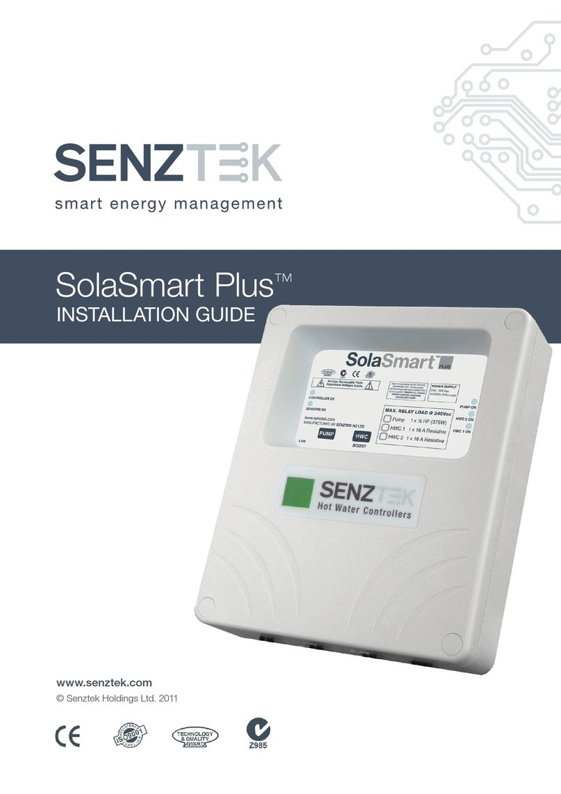
SolaSmart Plus™ User Guide
Version 2.0 – September 2013 Table of Contents
Table of Contents
The Display Panel...................................................................................................... 1
Solar Control.............................................................................................................. 2
BioSafe and Boost Functions..................................................................................... 3
Tariff Tables............................................................................................................... 4
Display and Diagnostics............................................................................................. 5
Trouble Shooting Guide ............................................................................................. 7
For technical help contact your installer or maintenance technician.
Installer Details:
www.senztek.com
Senztek Holdings Ltd. 2009

SolaSmart Plus™ User Guide
Version 2.0 – September 2013 Page 1
THE DISPLAY PANEL
CAUTION:
The SolaSmart-PlusTM
Dangerous Voltages present inside enclosure during operation.
has no user serviceable parts.
Protective enclosure must only be opened by qualified personnel.
Remove ALL power sources before removing protective cover.
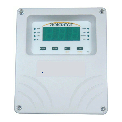
Pressing the NEXT button will cycle through an extended range of screens including the
time, what heating profile the controller is using, what speed the pump is running at (%) and
diagnostics. These are explained later in the manual.
The 3 sensor temperatures will cycle through Roof – Tank – Inlet. Indicated by the single
dot next to label on the display.
The 3 sensor temperatures will cycle through Roof – Tank – Inlet. Indicated by the single
dot next to label on the display.
The CONTROLLER OK
light is on when the
controller is operating
correctly.
The PUMP light comes on when the
pump is on (in normal or FROST
operation or when the PUMP button is
pressed).
For Dual Element model:
The HWC2 light comes on when
upper element is on.
The HWC1 light comes on when
element is on.
- (HWC) Button
Press to decrease guaranteed
stored hot water reserve (Comfort
level).
Press ENTER button and this button
together to initiate a one off Boost of
the hot water tank. Press same
buttons again to cancel.
The SENSORS OK light is
on when the sensors are
operating correctly.
Light off; check Roof
sensor.
Light flashing; check Tank
sensors.
+ (PUMP) Button
Press to increase guaranteed stored hot water
reserve (Comfort level).
.

SolaSmart Plus™ User Guide
Version 2.0 – September 2013 Page 2
SOLAR CONTROL
Differential The SolaSmart™ solar harvesting works by turning the pump on when the
difference
The pump turns off when the difference is less ‘Pump Off’ (Collector has cooled
and/or tank has heated up). This process repeats as the tank heats up.
between the temperature at the solar hot water collector (ROOF) and
the lower part of the tank (INLET) is at a set level ‘Pump On’
FROST The FROST function is designed to protect your collector and hot water system
from freezing and bursting. When this temperature is reached, the pump will
come on just enough to raise the temperature of the water by 2-3°C. Only a
small amount of warm water is needed to protect the collector and plumbing.
When the unit is in Frost Mode, the PUMP light will come on.
Topout The Topout temperature is the maximum temperature that the system will allow
the tank to heat to.
Topout Simple: The standard Topout method (Topout Simple) stops the solar
pump from working when the tank reaches Topout temperature. Topout also
works with the collector (roof) temperature so that BOTH the Tank and the
Collector must be below their respect maximum temperatures. The solar
harvesting cannot re-start until the collector cools down also (often after sun
down).
Advanced Topout: Advanced Topout function is an alternative to Topout
Simple that will allow the system to re-start solar harvesting if the tank
temperature falls below Topout but the Collector is still at Stagnation
temperatures.
This function can only work safely if the solar return pipe is below the upper tank
sensor (Tank).
Recovery is achieved by a three stage system which includes pulsing water
through the collector, the delay between pulses allows the dissipation of heat in
the pipes such that any steam should condense and not be present when the
water re-enters the tank and thus avoiding steam implosions (loud banging
noises in tank).
Also the Advanced Topout delays the onset of Stagnation with a 3 stage system
of actions.

SolaSmart Plus™ User Guide
Version 2.0 – September 2013 Page 3
BIOSAFE AND BOOST FUNCTIONS
Collector
BioSafe During BioSafe the pump is run for two minutes once the tank is above the
target temperature to sterilise the collector pipes.
BioSafe BioSafe runs periodically according to the settings. When heating for BioSafe
sterilisation the controller will start heating with the upper element (in a dual
element tank) first before completing the cycle by then heating with the lower
element. The BioSafe examination will continually reset while the tank
temperature is above BioSafe levels, so the sterilisation will only occur if the
tank has not attained BioSafe conditions over a 1 week period.
For installations where the Inlet (lower tank) sensor is below
BioSafe uses the Real Time Clock to determine when it should run and is
therefore immune to power outages of less than 14 days.
the electric
element, this is known as a ‘Mid Element’ configuration and the BioSafe will run
every 24 hours
Boost This is a ‘one –off’ operation that will reset when the Boost target temperature is
attained.
Boost can be initiated when the hot water is below the maximum boost
temperature (with a Solar installation this temperature might already be
surpassed). It can be cancelled by selecting Boost again, a toggle action.

SolaSmart Plus™ User Guide
Version 2.0 – September 2013 Page 4
TARIFF TABLES
Introduction
The Tariff Tables allow the controller to be setup in such a way as to minimise the
home owners electricity cost by matching the houses hot water use and
expectations to 4 different time bands for each day. Thus not heating too much hot
water. There are 3 to choose from to best suit the user.
Because the user can ‘turn down’ the profile with the comfort control feature (the
tables here = 100% user comfort setting) the table must represent the likely
maximum expected stored reserved hot water.
The options are;
1. MAX - non over rideable by user comfort control
2. High
3. Med
4. Low
5. Off – will not heat during this time period
Table 1 shows all the variables in Tariff Table. Only entire tables can be selected
on stand-alone SolaSmart-PlusTM controllers. These individual Tariff table settings
are fully adjustable with the optional accessory DisplaySmart-PlusTM
H1
(Standard)
H2
(Night On)
H3
(Night Off)
Band 1 Band 2 Band 3 Band 4
Band Start Time 7:00 9:00 15:00 23:00
Hot Water Level High High High High
Band 1 Band 2 Band 3 Band 4
Band Start Time 7:00 9:00 20:00 23:00
Hot Water Level High High High Max
Band 1 Band 2 Band 3 Band 4
Band Start Time 7:00 9:00 20:00 23:00
Hot Water Level High High High Low

SolaSmart Plus™ User Guide
Version 2.0 – September 2013 Page 5
Comfort
Control
The Comfort Level is an easily adjustable user control that allows the
efficiency vs guaranteed hot water storage balance of the system to be
managed. The control is easy to adjust and can be altered at anytime to suit
changing circumstances, weather, guests in house and such.
The + and –buttons on the front panel will by default adjust the
‘comfort level’ and the 7 segment display will indicate what the comfort %
setting is after each update. There are also optional external devices which
can adjust this value in addition to the front panel of the controller.
The Comfort Control manages the electric boost heating only.
Set higher for more guaranteed hot water
Set lower for more savings
This control was included as a solution to the problem that different users
have different hot water usage vs savings expectations.
The Comfort Level percentage is not a direct temperature control; rather it
uses sophisticated computer logic to determine the best temperatures and
which sensors or elements in conjunction with the selected HWC profile to
realise an optimised system for the user’s expectations of stored hot water.
At first it might be best to start with a maximum or high setting and gradually
reduce over some time (maybe days) until the best balance is found.
Comfort set to 0% = Holiday mode and the tank will not heat with the electric
elements except if BioSafe sterilisation is required.
Note: The last Comfort setting is written to permanent memory 5 minutes
after the last adjustment. If power is removed before the 5 minutes has
elapsed the setting will revert to the previous stored value.
DISPLAY AND DIAGNOSTICS
Introduction The Display is normally a scrolling display of 3 screens. Every 5 seconds the
display scrolls to the next screen.
Screen 1:
Roof °C The dot next to the “ROOF” will be lit up when the Roof Temperature is on
the display. If the sensor is faulty, “Opn” or “Shrt” will be displayed depending
on the fault condition.
Screen 2:
Tank °C The dot next to the “TANK” will be lit up when the Upper Tank Temperature
is on the display.
Screen 3:
Inlet °C The dot next to the “INLET” will be lit up when the Inlet (Lower Tank)
Temperature is on the display.
Note: To view screens 4-6, press This will activate advanced
diagnostics mode for 10 minutes, after which time it will revert to the
temperatures only

SolaSmart Plus™ User Guide
Version 2.0 – September 2013 Page 6
Screen 4:
PWM Duty
Cycle %
Screen 5:
Time
Screen 6:
Diagnostics
Shows the speed of your variable speed pump (0 to 100%). Only applies
when using a PWM pump.
Time is shown in HH:MM format.
Segment 1:
Solar Rule that is currently active
- = IDLE
Φ= Frost
δ = Differential
τ = TopOut (D1 Stage 1, D2 Stage 2 , D1 & D2 Stage 3)
β= Collector BioSafe
Ε= Error
Segment 2:
HWC Rule that is currently active
-= IDLE
ρ = Reheat
β= BioSafe
0= Boost
Ε= Error
Segment 3:
Active Element: Λ= Lower, Υ= Upper
Segment 4:
Active Tariff Band: 1to 4
E.G. δρυ2 = The solar pump is running (differential), the tank is using an
element to heat the tank (reheat) and that element is the upper
It is time period 2.
Procedure for Setting the Time and Hot Water Profile:
1. Press and hold for 10 seconds
2. The ‘Hours’ digits flash
3. Adjust with and
4. Press
5. The ‘Minutes’ digits flash
6. Adjust with and
7. The present Hot Water Profile number will flash e.g. Η3
8. Adjust with and
9. Press
10. Press to save and exit

SolaSmart Plus™ User Guide
Version 2.0 – September 2013 Page 7
TROUBLE SHOOTING GUIDE
Before you call for repair or servicing check the following table
Also note down any observations at the time of the fault, especially the 3 sensor temperature
readings (on the display) and if possible what the Status screen was displaying.
Symptom Possible Cause Solution
No operation, no
lights ON No power/fault
Check mains outlet is switched on
Sensor O.K. light OFF Roof sensor not detected
Possible broken sensor cable
Check sensor is plugged in at
controller
Call for repair
Sensor O.K. light
flashing Inlet or Tank sensor not detected Call for repair
Pump not running,
while sunny outside.
Pump light ON
Pump damaged or disconnected.
Pump timer has turned pump off
Controller fault
See if pump has become unplugged
Wait one minute for the pump to
restart.
Call for repair
Pump not running,
while sunny outside.
Pump light OFF
System in Topout
Check diagnostics display if controller
is in Topout, the first digit will be τif in
Topout. If so then this is normal.
Pump is running
continuously Pump is cavitating
Special Installation
Airlock in pipe
If pump sounds like stones are
passing through it, the pump may be
cavitating and so not moving water.
Call for repair
Long pump times may be normal for a
variable speed pump or a special
installation.
Pump only comes ON
when Roof sensor is
above 100ºC
Advanced Topout method
Normal operation for Advanced
Topout.
Pump only comes ON
for few seconds every
few minutes
T2 Advanced Topout and recovery
method in action
Normal operation for Advanced
Topout and Recovery. This prevents
banging in tank (steam implosions)
HWC light stays on
too long (more than 6
hours)
HWC power not getting to element
Element open circuit (blown)
Excess water draw off or leak
Read tank temperature
If < 50ºC issue will be interrupted
power or a faulty element. Call for
repair
If > 50ºC issue will be tank thermostat
will not allow controller to reach target
temperature (usually in BioSafe
heating). Arrange for tank thermostat
to be adjusted to maximum by
qualified personnel only


Senztek NZ Ltd ºSenztek Australia Ltd Senztek UK Ltd
Other manuals for SolaSmart Plus
1
Table of contents
Other Senztek Controllers manuals
