www.flycolor.net 251400-1110 V1.0
*Picture for reference only.
04 Operation instruction
05 Programming parameter
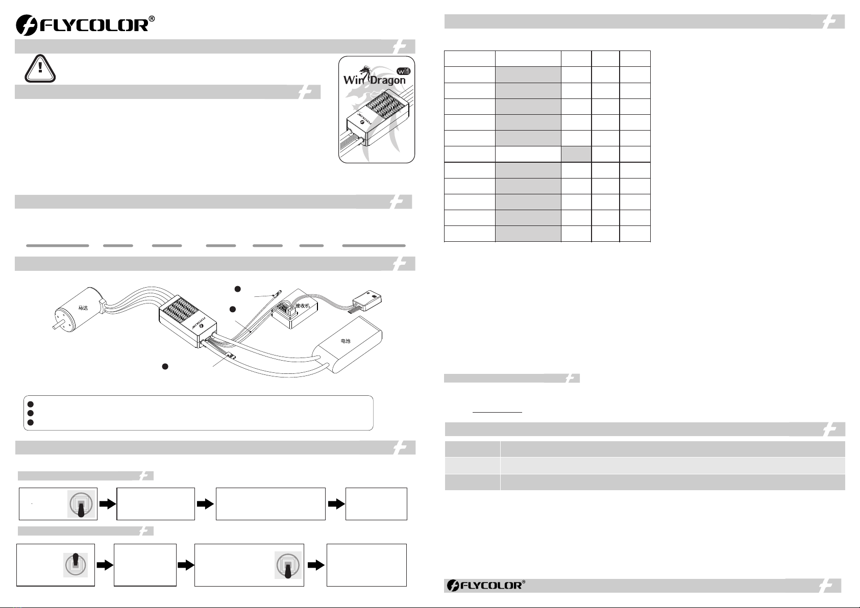
*Please ensure all solder joints are insulated with heat shrink where necessary.
2
Throttle signal wire
Reverse signal wire
1
BEC
WiFi Trans wire
3
ESC
Motor
Battery
Receiver
ATTENTION
User Manual
Brushless ESC For Airplane
01 Main features
03 Wiring Diagram
Thank you for using our product. Any improper operation may cause personal injury or damage the
product and relevant equipments. This high power system for RC model can be dangerous ,we strongly
recommend reading the user manual carefully and completely. We will not assume any responsibility for any
losses caused by unauthorized modifications to our product. We have the right to change the design,
appearance, performance and usage requirements of the product without notice.
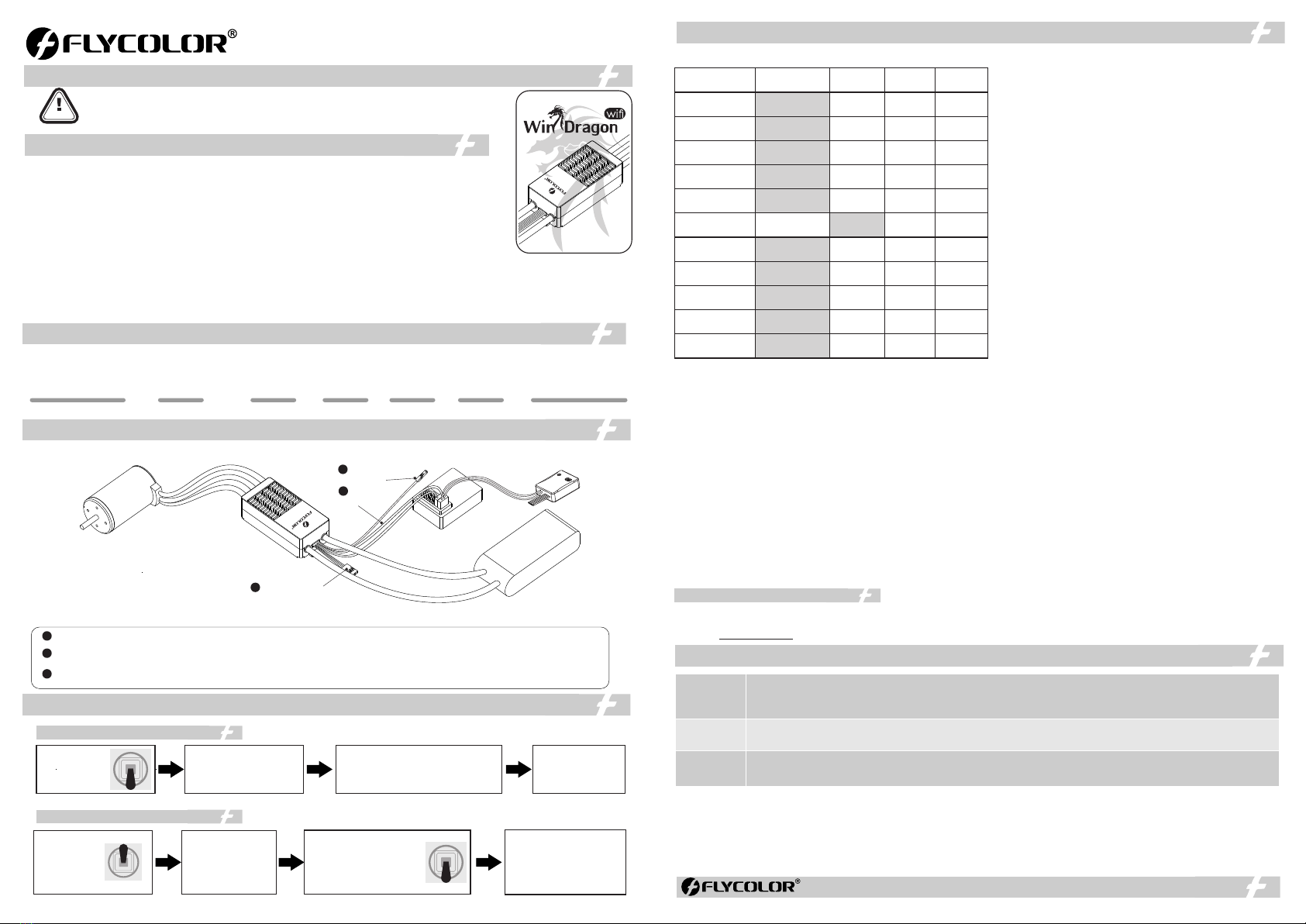
02 Specifications
Burst Current
(Good heat dissipation)B EC Size
(For reference)
Model
LiPo
Weight
(For reference)
Con. Current
(Good heat dissipation)
200A 250A 285g 108.5x46.5x32.6mm
5-14S
WinDragon wifi 200A
NO
● Use powerful & high performance microprocessor, compatible with various brushless motors. Unique
circuit design, strong anti-interference.
● Supporting maximum 210K erpm.
● Start mode can be set, throttle response fast, speed regulation linear stability. Compatible with fixed wing
aircraft and helicopters.
● Multiple protections ensure the equipments safety.
● High power safety performance, when power up the motor will not start immediately wherever the throttle
stick is.
● Beeping alarm can indicate working condition.
● ASC F (Active Switch Continued Flow)technology, higher efficiency, reduce heat generation massively.
● Wifi Trans for programming, programming via mobile phone AP P (extra Flycolor Wi-Fi Trans needed).
● Supporting close-range monitoring and recording of real-time flight data via mobile phone APP (extra Flycolor Wi-Fi Trans needed);
● Reverse function, supports to reverse the motor rotation during the flight to achieve deceleration.
● Aluminum covers, effective heat dissipation, slow down temperature rise.
1
2
3
Reverse signal wire: plug it into an two-stage switch channel on the receiver ,to reverse the motor rotation during the flight.
Throttle signal wire: plug it into the throttle channel on the receiver, the white wire is for transmitting throttle signal, the black wire is
ground wire.
Wi-Fi Trans wire: connect with Flycolor Wi-Fi Trans, supports programming and detection of real-time data at close range via mobile
phone APP.
1.Normal start-up
2.Throttle Range calibration
Turn on the
transmitter,
move the
throttle stick to
the top position.
Connect E SC with
battery. Wait for 2
seconds, after motor
emits 2 short "BEEP-
BEEP",the full throttle
position is memorized.
Move the throttle stick to
the bottom position in 3
seconds. Then waits for 1
second, the“zero throttle“
position is memorized.
Motor emits short " BEE P-"
few times, sound times is
Lipo battery cells.
Wait fo r 1 seco nd, It m eans
“No Brake” when motor emit
continuously 1 long an d 1
short tone . It mea n s “Brake
is availab le” when motor
emits a long tone. ES C is
ready for working now.
Turn on the
transmitter,
move the throttle
stick to the
bottom position.
Connect ESC with battery,
wait for 2 seconds,motor
emits short "BEEP-" few times,
sound times is Lipo battery
cells.
ESC is ready for
working now
Wait fo r 1 seco nd, It m eans “No Brake”
when motor emit contin u ously 1 long and
1 short tone.
It means “Brake is a vailable” when motor
emits a long tone.
Parameter programming via AP P
Start-up
Protection
Over heat
protection
ESC will cut off output if it fails to start the motor within 3 seconds by accelerating throttle. you need to move the throttle
stick back to the bottom position and restart the motor.( The possible causes : Bad connection or disconnection between
ESC & motor , propellers are blocked, etc)
When ESC temperature is higher than 100 ℃,it will reduce output power (throttle will be limited below 40%) for protection,
leave some power for motor to land , when the temperature Reduced to 80℃ , ESC recover to normal running mode.
When ESC detects the loss of throttle signal for over 1 seconds, it will cut off power or output immediately to avoid an
even greater loss caused by the continuous high speed rotation of propellers. E S C will resume the corresponding output
after the normal signal is restored.
Throttle Signal
Loss Protection
06 Protections
Alarm tone: (To judge the abnormal cases via alarm tone )
1.Alarm tone of signal loss : when E S C detects no signal , motor will emit the alarm tone “Beep-、Beep、-Beep-”(alarm tone
emits every 2 seconds).
2.Alarm tone of throttle not in the zero throttle position: throttle not in the zero throttle position, motor will emit
“Beep-Beep-Beep-Beep-Beep-” ( urgent single short tone).
3. Alert tone of narrower throttle range: when throttle range is set too narrow, motor emits “Beep-Beep-Beep”(harried alarm tone
emits last for 2 seconds). You must throttle range again.calibrate
[1]NO(Default) [2]Soft [3]Heavy [4]Very heavy. 1. Brake:
2. Cutoff voltage: 2.8V - 3.8V (Default 3.0V).
3. Timing:0° - 30° (Default 15°).
4. Startup Mode: Start up with linear accelerator.
[1] Normal: No delay in throttle response. (Default).
[2] Soft: It will take 6 seconds from 0% to 100% throttle.
[3] Very soft: It will take 12 seconds from 0% to 100% throttle.
5.Governor mode :
If the Governor mode is activated, E SC will try to keep the
motor in a fixed speed ( usually the throttle curve is a horizontal
line, you can change the preset motor speed by changing the
height of the line).
[1] OFF (Default)
[2] Low , "Low constant speed" mode , 10000-20000RPM for
two poles brushless motor .
[3] High, "High constant speed" mode , above 20000RPM for
two poles brushless motor .
Note: Governor mode function is automatically disabled if the
throttle value less than 60%.
6. PWM frequency: [1]8KHz [2]16KHz(Default) [3]24KHz
For some motors with many poles and high speed, the higher
PW M frequency can make motor run smoother, but at the same
time, the switch loss is increased and the temperature rise is
higher .
*Shadow parts are factory default value
234
NO Soft
16KHz8KHz
5S-14S
24KHz
2.8V-3.8V
( 3.0V)Default
0°- 30°
( 15°)Default
1. Brake
1
Heavy Very Heavy
Normal Soft Very Soft
OFF Low High
Reduce
cutoff Cut off
Auto
Iterm
9 Motor rotation.Normal
Reversed
10.AS CF OF F ON
2.Cutoff voltage
3.Timing
4.Startup mode
5.Governor mode
6.PWM frequency
7.Voltage cutoff
option
8.Battery cells
11.Reverse
function
OFF ON
7. Voltage cutoff option:
[1] Reduce cutoff(Default ): the voltage drops to the set low-voltage protection threshold , ESC will reduce the power then cut off the
motor output.
[2] Cut off: the voltage drops to the set low-voltage protection threshold , ESC will cut off the motor output immediately.
Battery cells [1] Automatic calculate(Default) [2]5S -14S .8. :
You select automatic calculate, and also can select the options according to your battery cells.
9.Motor rotation:
[1]Normal(Default):Default direction of motor rotation;
[2]Reversed:Change the motor rotation.
10.Active Switch Continued Flow [1]Off (Default) [2]On :
ASC F (Active Switch Continued Flow) technology, higher efficiency, reduce heat generation massively.
11.Reverse function [1]Off (default) [2]On :
Plug reverse signal wire into an two-stage switch channel on the receiver ,to reverse the motor rotation during the flight to decelerate.
The lowest point of the pulse width range of the 2-stage switch channel must be less than the lowest point of throttle. (e.g. the lowest point of
throttle is 1000, then the lowest point of pulse width of 2-stage switch channel should be less than 1000).
Effective conditions : 1. Reverse function - on; 2. Governor mode - off; 3. Brake - on.
Flycolor Wifi Trans is used for programming via Flycolor App; Flycolor App V1.2 version or higher is required for this product.
Please see Flycolor Wifi Trans and Flycolor App instructions for details.
Or visit www.flycolor.net for more information.