Flygas F.050 Manual

Installation and maintenance manual for mechanical fuel pump FLYGAS –Version 1.2 Experimenter
1
INSTALLATION AND
MAINTENANCE MANUAL FOR
MECHANICAL FUEL PUMP
Cod. F.050 and F.051
Version 1.2 “Experimental”
All the information, the technical data and the specific drawings reported in this manual are owned by FLYGAS
and they cannot be reproduced neither entirely nor partially without previous agreement and written authorisation
by FLYGAS ITALIA.
Approval of translation to best knowledge and judgement –in any case the original text in Italian language is
authoritative. COPYRIGHT - FLYGAS
.

Installation and maintenance manual for mechanical fuel pump FLYGAS –Version 1.2 Experimenter
2
Index
1. FOREWORD.........................................................................................................................4
2. KIT FUEL PUMP FOR ROTAX DESCRIPTION OF THE PARTS ..................................8
3. TECHNICAL DATA ............................................................................................................8
4. INSTALLATION..................................................................................................................9
5. INSTALLATION ON ROTAX 914:..................................................................................10
6. OPERATION ......................................................................................................................16
7. FUEL SYSTEM ..................................................................................................................17
8. FIRST STARTING .............................................................................................................20
9. BEFORE EACH START....................................................................................................21
10. POSSIBLE FAILURES ......................................................................................................22
11. MAINTENANCE SYSTEM...............................................................................................23

Installation and maintenance manual for mechanical fuel pump FLYGAS –Version 1.2 Experimenter
3
WARNING !
This Manual is an integral part of your kit and shall be kept with it for
future reference.
Retain this Manual in a suitable place and when consulting it, take care
of not spoiling it.
Should your kit be resold, entrust it to the new owner who will obviously
need the information contained.
This Manual consists in 24 pages including cover.
RIGHT OF WITHDRAWAL
The buyer has the right to withdraw from the purchase of this kit if within 10
days of purchase, after received this kit, considers the unsuitability of their
vehicle to receive the installation of this system.
In this case Flygas reserves to repay the full amount paid (equal to the
invoice) and collect all the material, as long as it is intact in all its parts, not
altered or defaced and stored under appropriate conditions, without charge
or duty by the purchaser.
The material should be delivered free at the headquarters Flygas.
Insurance
No insurance is included in the purchase of our kit.
Please, note that the installation of our Mechanical Fuel Pump kit could be
change the basic characteristics of the engine and of the vehicle. It’s so
necessary to review the insurance contract verifying insurance coverage and,
in case, examine the possibility of creating a new insurance policy that
permits such changes.
In case of accident or in case of damages caused to property or third persons,
Flygas will not be liable in any way.

Installation and maintenance manual for mechanical fuel pump FLYGAS –Version 1.2 Experimenter
4
Congratulation for your choice to use this FLYGAS product.
Designed and built entirely by Flygas, it is the result of the long path that the company carried out
within motoring field. With the use of our system, designed and manufactured in Italy, you will be able
to increase the reliability of your engine.
Before starting with this kit read this manual carefully so as to understand the contents clearly: consult
it whenever any doubt arise.
The sections are proposed in order to know step by step all the functionalities of our product.
The texts are easy to be understood and accompanied by pictures.
This manual contains information which are useful for you safety. Please observe carefully the
indication contained and perform the recommended procedures which, if not properly observed, could
result in damage of the equipment or could cause personal injury.
Warrantee
The warranty is limited to the replacement of items that, send ex-works to Flygas, are considered
defective for reasons attributable to us; we exclude any responsibility for possible damages to
persons or properties. This product is guaranteed for one year from date of delivery or 50 hours of
flight.
Purchase date: __ / __ / ____
Flight hours at the moment of sale: ______________
Engine type: ________________
Serial Number : ________________
Within 30 days from the date of purchase the buyer must send to Flygas the sheet in which is
clearly indicated the date and the effective hours till the date of the installation.
Otherwise the warranty is void.
.1. FOREWORD
Installation and maintenance manual for mechanical fuel pump FLYGAS –Version 1.2 Experimenter
5
In order to make the reading and the comprehension of the manual easier, the important
information are marked by the following symbols:
The safety Alert Symbol means ATTENTION! Be careful! Carry out all
the precautionary measures to avoid damages for your personal
safety.
The in-observance of the instructions marked by the following symbol of
WARNING may result in serious damages of the vehicle, and could
cause injures to the operator or to the people involved in inspection or
repair of the vehicle.
A NOTE provides key information to make procedures easier and
clearer.
This manual is developed to provide you basic instructions for installing on your engine the
Mechanical Fuel Pump and its maintenance in order to prevent accidents and damages caused by
human error.
Our system is compatible to be installed on different models of engines; so this handbook should
necessarily be integrated with the manual of the engine on which it is installed.
This manual contains important safety information: follow the indications described and perform the
recommended procedures which, if not properly observed, could result in damages of the
equipment or could cause personal injury.
Regular inspections and careful maintenance will ensure you a safe and proper usage of this kit.
Read this manual carefully and completely before operating this kit. Do not
attempt to operate until you have attained a complete knowledge of its controls
and operating features; please carry out the first trial in complete safety
conditions to get acquainted with the several controls.
Regular inspection and maintenance will make your engine safe over time
without compromising reliability.
The information and the description contained in this Installation Manual are correct at the time of
publication. FLYGAS, however, maintains a policy of continuous improvement both in terms of the
performance and of reliability of its products, without imposing any obligation to install them to
update the products built previously.
FLYGAS reserves the right at any time to discontinue or change specifications, drawings, features,
models or equipment without incurring in any obligation.
For any questions concerning this manual, please contact Flygas Italia.
The kit can be installed exclusively by certified technicians, authorized by local aviation authorities
with the basic knowledge of this product.
Mechanical Fuel Pump fuel system, must be installed only on engines, where the
sudden shutdown does not cause any danger. If the kit is installed on aircraft,
never fly in unsafe conditions (altitude, speed, location...) or other unsafe

Installation and maintenance manual for mechanical fuel pump FLYGAS –Version 1.2 Experimenter
6
circumstances. In case of sudden power loss or switching off the engine pilots
must be able to make an emergency landing. Flying exclusively on flat areas and
open countryside without going over the airfield. The aircraft fitted with this kit has
to fly only in daytime light conditions and visibility (VFR - Visual flight rules -). It is
prohibited the installation on vehicles supported by rotary wing (as helicopter,
autogyro and other aircraft like these). It is strictly prohibited to install it on
acrobatics aircrafts (inverted flight, etc. ..). This kit is designed for a possible
application on aircraft used only under VFR conditions, which have the ability of
controlled landing even with the engine off or damaged.
Failure to observe these instructions excludes the system manufacturer from any liability.
For the variety of models, equipments, and types of aircrafts on which you can install the
Mechanical Fuel Pump FLYGAS gives no warranties or documentation about the adaptability of
this kit on a particular type of engine or vehicle.
Moreover, FLYGAS gives no warranties regarding the compatibility of this kit with any other parts,
element or system that can be chosen by the manufacturer / user for the application on the plane.
FLYGAS recommends you to select and install a proper aircraft instrumentation.
These tools are not included in the kit.
Before each flight be sure that all instruments of motor control are operational and reliable.
Make sure that they can be reached in case of emergency.
Before starting the engine with propeller installed, the pilot must ensure that the surrounding area
is clear of obstacles, people and other vehicles.
Start the engine with brakes and hand on the throttle control and follow the necessary heating
time.
Turn on the engine with propeller installed only in special open places away from people especially
if they are not employees!
Prevent use by unauthorized persons, inexperienced people or people who haven’t read and
understood this manual.
Certain geographical areas, altitudes and weather conditions presents a higher
risk than others. The Mechanical Fuel Pump may require more protection from
the weather as humidity, dust and sand, or an extra maintenance.
Improper installation, use of inappropriate electrical connectors and pipe fittings of non-standard
aircraft, discharge the manufacturer of the kit from any liability. Unauthorized modification plant fuel
automatically exclude the manufacturer of the kit from any liability.
Replacement parts must be the same authorized by FLYGAS and described in
this manual; the usage of non original spare or used parts discharges the
manufacturer from any responsibility.
This kit has not been tested for safety and durability standards for the aircraft. All
the risks involved will be borne by the user. The added weight of the kit varies
inevitably the centre of gravity and moment of inertia on the three axes aircraft.
Before you make a good flight it’s necessary to check what that change involves
and be sure to carry out all the consequent changes.
While refuelling, protect the engine and supply system from contamination and
exposure.

Installation and maintenance manual for mechanical fuel pump FLYGAS –Version 1.2 Experimenter
7
The kit Mechanical Fuel Pump can cancel the guarantees issued by the engines manufacturer.
In addition to compliance of the instructions contained in our manual and that of the engine
manufacturer, all the general measures of safety and accident prevention must be observed, as
well as legal laws and the rules of any aviation authorities.

Installation and maintenance manual for mechanical fuel pump FLYGAS –Version 1.2 Experimenter
8
2. KIT FUEL PUMP FOR ROTAX
DESCRIPTION OF THE PARTS
Mechanical Fuel Pump Kit by Flygas consists of the following elements :
N 1 Maintenance and installation manual
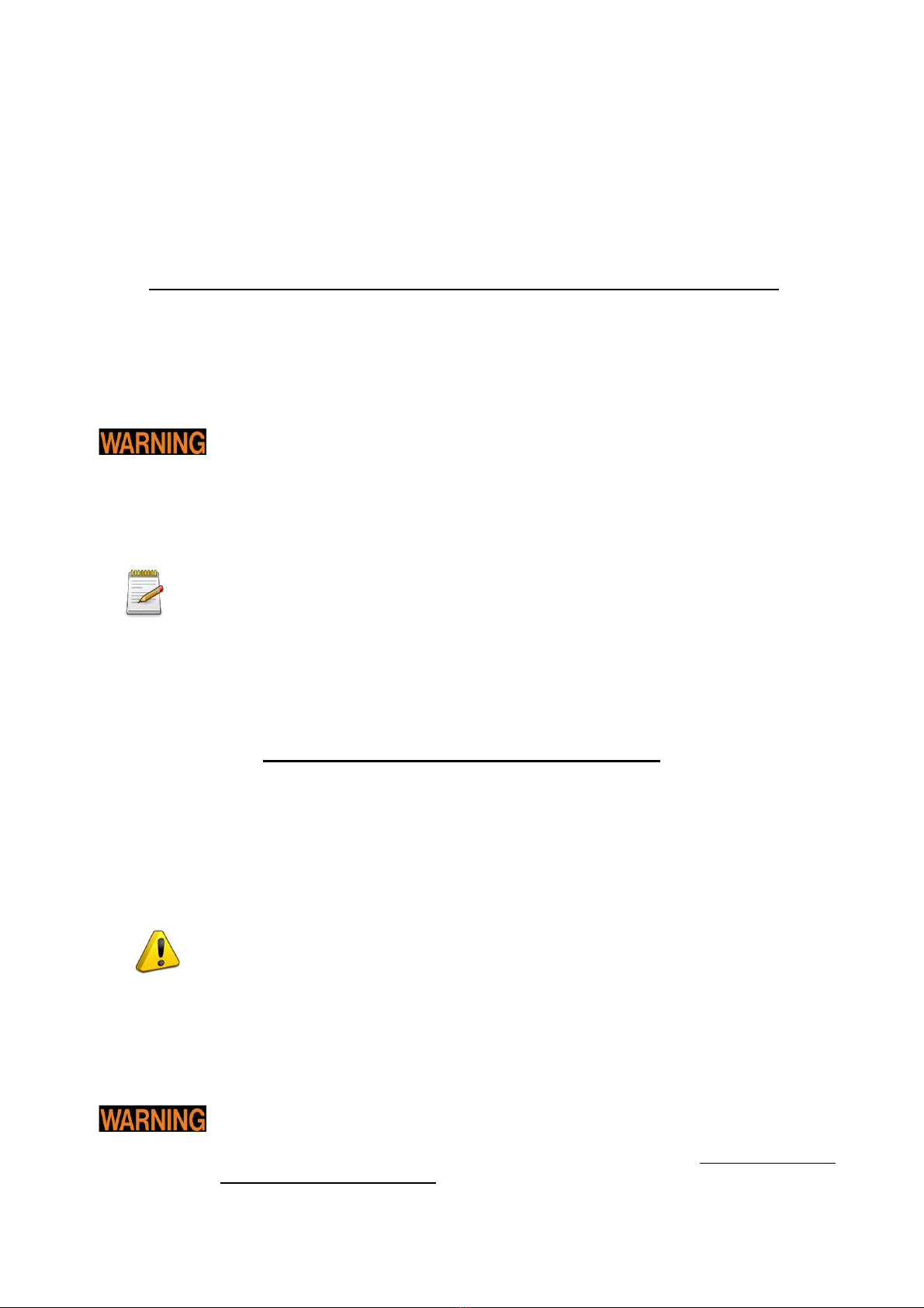
N 1 Assembled and tested Fuel Pump By Flygas
N 1 Joint type Oldham
N 1 Aluminium screwed M46x1,5 driving joint
N 1 Aluminium “bell support”
N 1 Aluminium support plate
N 3 Allen screw M5 length 12mm
N 3 Allen screw M5 length 16mm
N 3 Allen screw M6 length 16mm
N 1 Diameter 6mm pin L14mm
N 2 Diameter 4mm pin L16mm
3. TECHNICAL DATA
Total weight installed 680 grams (about one mechanical fuel pump)
Maximum pressure reached 14Bar
Maximum continuative pressure 3Bar
Maximum Speed 7000 RPM
Maximum draft depth is 900mm
Pressure regulator of fuel, is required on the plan
Flow of gasoline in function of RPM and Pressure
None of these elements has been designed and built for flight. Their use on
aircraft is at the sole judgment of the user of the vehicle
.
9
4. INSTALLATION
Before installing read this book carefully. The manual provides basic information
for the correct installation of the entire system on the engine and its proper
maintenance. A lack of attention may cause serious damage to both structural
(weakening of the engine or mechanical parts directly linked to it) and physical.
Since the reading of the instructions will not eliminate the risks, the understanding and application
of the information listed below will allow proper installation, operation and maintenance.
At least ONE ELECTRICAL FUEL PUMP MUST BE INSTALLED for emergency
and safety reasons! This electrical fuel pump must be run in all condition where
eventually shut-off of mechanical fuel pump, could created an dangerous
situation.
The installation of the kit and its maintenance must be performed only by certified
technicians, qualified and authorized by local aviation authorities.
The illustrations in this manual show the basic construction. They cannot
represent all the details and the exact form or shape of all the components with
the same or similar function.

10
5. INSTALLATION ON ROTAX 914:
1) Dismount the battery from the vehicle.
First disconnect the negative terminal to prevent a sudden starting of the engine
or sudden sparks may cause fires. Reinstall the battery only after complete
installation.
2) Empty the tanks completely and close with taps
Pay particular attention to the escape of fuel during the disconnection of pipes
and fittings. In the section of pipe that goes from the fuel pump may be high
pressure. Do not work near heat, flame or sparks (the only rotation engine, if the
"magnets" are not grounded, causing sparks to high voltage, in the order of
15,000 Volts!).
3) Disassemble the propeller in order to prevent that the first test ignition or an
undesired ignition may hurt people.
6) Ensure all threaded parts through a special lock steel wire or thread lock product
by adopting all necessary measures to perfect fit against loosening caused by
vibration, expansion, etc. ...
The presence of particles of dirt may damage the various and important
mechanical seals causing the premature wear by abrasion. Therefore, avoid that
parts of products used as chemical sealing agents or Teflon enter the pipes
during installation and maintenance. Please notice that this material may damage
the mechanical seals and moreover could block the flowing of gasoline, air and
oil. Whenever you install a pipe, especially if new, it is essential to wash it; let
flow inside a substantial amount of fuel to remove dirt and waste.
The manufacturer guarantees the perfect performance and durability of
the components supplied only with gasoline which is unpolluted by water and dirt, and above all
the producer ensures the physical and chemical compatibility of its components only for gasoline
called "green" normally sold in Italy without any additives.
Any forcible action, intervention or replacement of parts without written permission from
Flygas, discharge the manufacturer from any liability in case of damage or malfunction of
the system

11
1. Install the Driving Joint with Loctite 243
2. Tight the Driving Joint with torque aprox 30Nm
3. Insert N°2 pin 4mm diameter in Rotax case
12
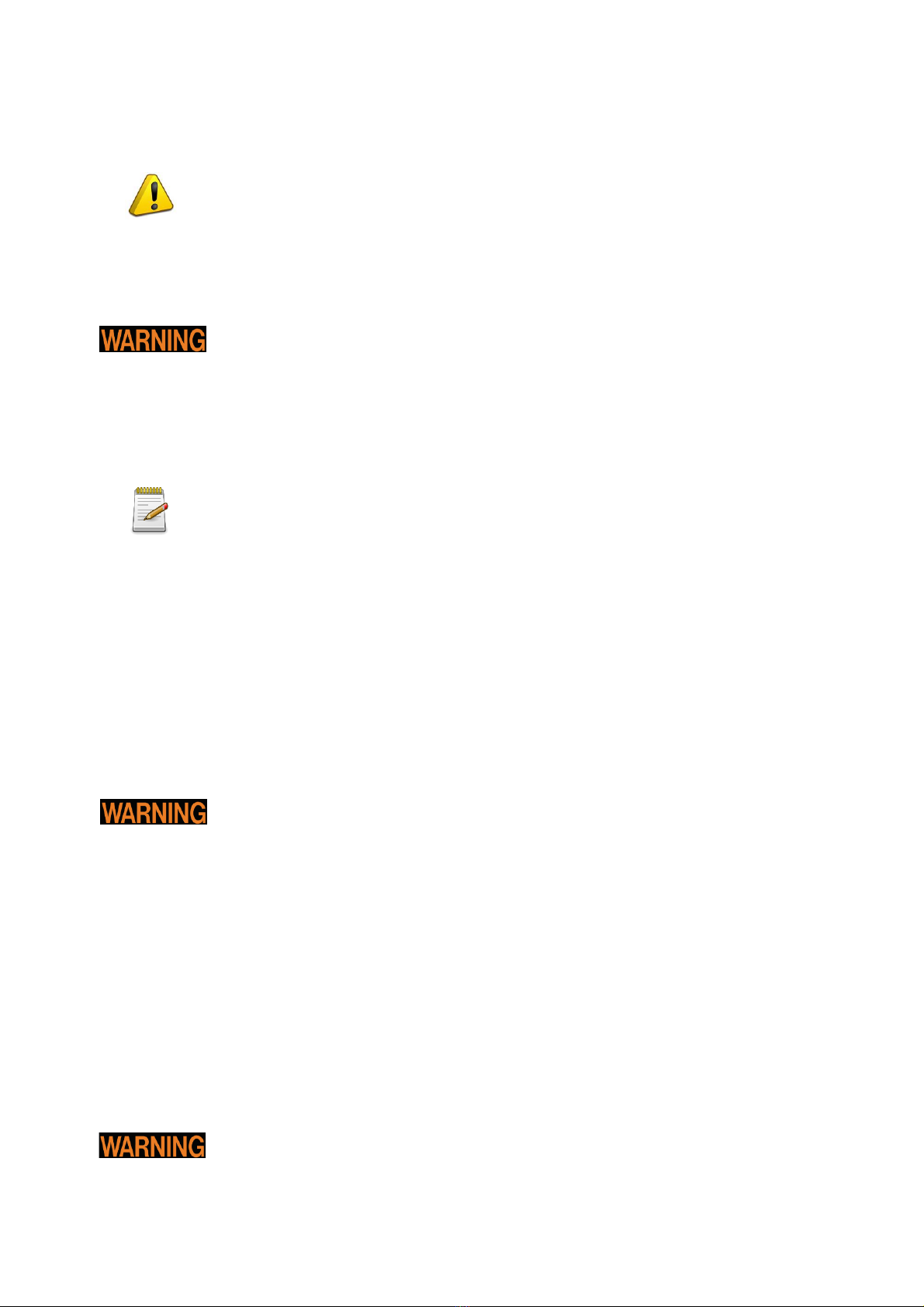
4. Install the support plate, with N°3 Allen screw M6
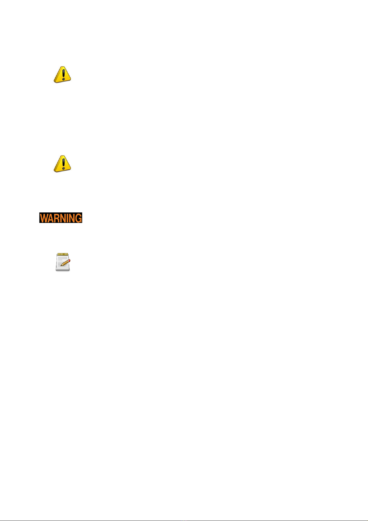
5. Insert the drive pin 6mm (That temporary operations is necessary to find a right
Axial Alignment between Fuel Pump and Crank-Shaft )
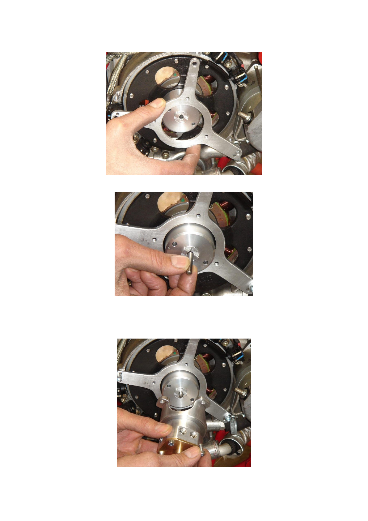
6. Install the Fuel Pump and Bell and screw with Loctite 243 the N°3 Allen Screw
M5 (after never remove more this N°3 Screw, otherwise will be necessary repeat
this operations)

13
7. Check the distance/space from the tooth of Drive Shaft and from tooth of Pump
Shaft; Minimum distance must be 0,65mm “0 Plus 0,1mm”
8. After remove the Plate, the Bell and the Pump without disconnect this 3
parts!
During installation and maintenance be sure that no pipe or electric cable is near
to potential electrical shortcuts, electrical shocks (always possible especially
coming from high voltage cables candles) and close to hot surfaces (above 50 °
C ..) Do not run pipes or wires inside holes on not properly protected sheets, do
not lean them on sharp edges or on any other cutting element. The thermal
expansion of materials and their vibrations during operation of the engine can
cause cuts, peeling and abrasion of the objects placed in contact with them.
If you have choose a Fuel Pump for Electronics Fuel Injection E.F.I., insert a
specific filter for injection systems which is resistant to injection pressure of 3 bar
between the output pump and the input rail of injectors in order to be able to
retain any dirty or waste
With regards to the connection of the pressure / vacuum, instead, use suitable pressure tube
resistant to pressure and especially to gasoline and oil.

14
Use the entire length of wedge to make the pipe as fit as possible to the plug.
In order to avoid the pipe to slip off from its housing accidentally, fasten it using the proper clamps
free from edges that may cut it.
If necessary, insert a anti pulsations. This will avoid excessive “stress” to the
gauge, the carburattors, the injector and all elements could be deteriorate if
pressure is not linear and constant enough.
The tests will be performed by experienced and qualified people with the use of
tools to carry out the controls properly.
9. Remove the pin 6mm and install instead the Oldham Joint with grease

15
10. Install again the Plate, The Belt and Fuel Pump and tight N°3 Allen Screw M6
at 10Nm
16
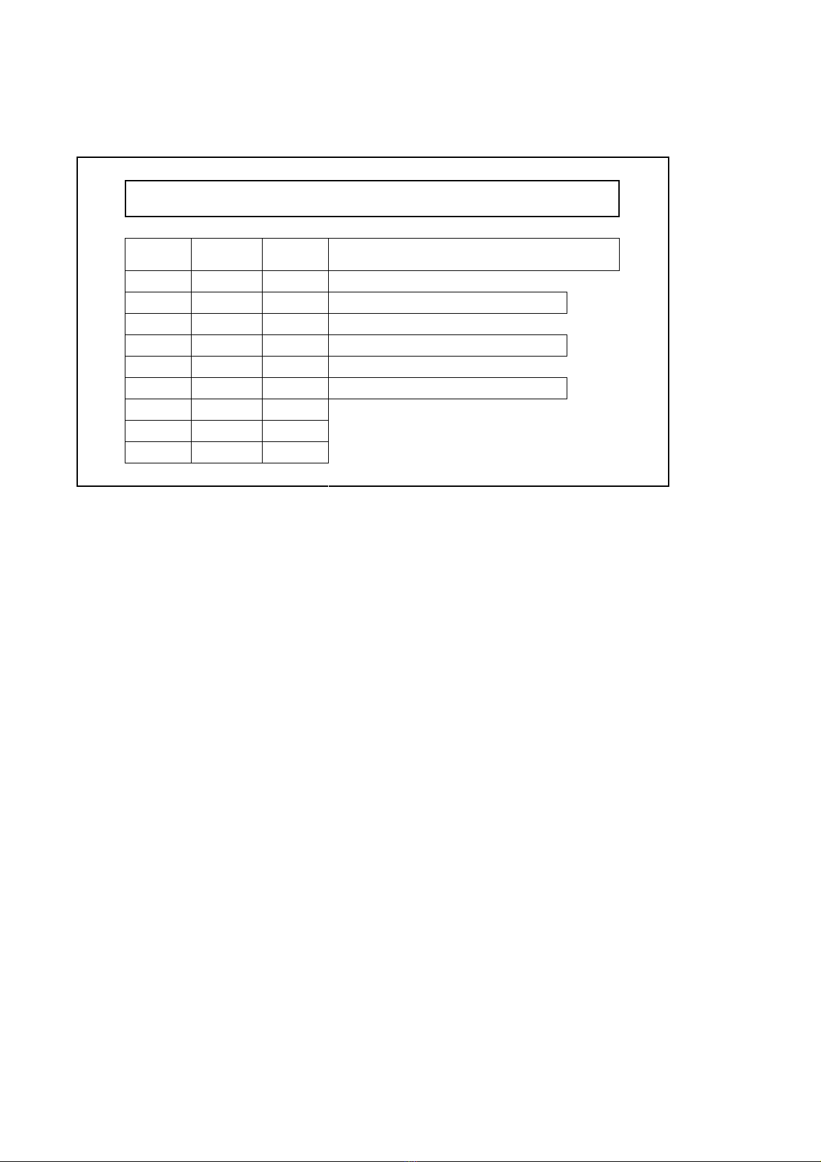
6. OPERATION
Performance Test of Mechanical Fuel Pump installed on your
engine
RPM
Pressure
Fuel
Flow
Draft Depth Fuel Level:
2000
2500
Fuel Temperature:
3000
3500
Hour/Km:
4000
4500
Data:
5000
5500
5800
Never carry out the steps during the flight only for testing. Perform tests on the ground
with tied or braked vehicle and be sure to observe all the safety instructions.
17
7. FUEL SYSTEM
Shape and arrangement of the fuel system must ensure the functioning of the engine within the
limits given.
Fuel pressure at the carburettor system in atmospheric conditions Rotax 914:
Maximum …..……………….......0,35bar
Minimum ……….…………........0,15bar
Nominal …….……….…….......…0,25bar
Minimum Flow …..95 Lt/hour @5800rpm
The exceeding of the specified maximum fuel pressure can lead to a overtaking
of the seal of the float valve inside the carburettor resulting in an engine
shutdown.
In supercharged or turbo engines, the “Boost Pressure” increase the maximum
fuel pressure in equal measure of boost pressure , thanks at “pressure fuel
regulator”.
Fuel pressure Electronics Fuel injection system:
Maximum …………......………..3Bar*
Minimum Flow ………..…100Lt /Hour*
* Measured with the pump @15°C Fuel temperature
The fuel lines must be designed according to the latest standards required by the
manufacturer as FAR or JAR aircraft. To prevent the formation of steam inside
the pipes, all the pumps and fuel lines must be isolated against heat and kept at
a suitable distance from all hot parts such as exhausts, air and oil cooling
system. In some cases it is necessary to direct a flow of fresh air.
During all operations on the fuel system, pay attention that gasoline do not spill
out during the pipe and joint disconnection. In the section of pipe that goes from
the fuel pump to the engine entrance may be high pressure. Do not work near
heat, open flames or sparks.
18
Connect one pipe from the 4mm diameter fitting on the bottom of the fuel pump, to outside. That
“emergency hose”, will bring far from exhaust or engine department, the eventual leakage of fuel.
The system carburettors will be re-checked completely, taking care to protect the components from
any kind of impurity, especially during installation and then make sure you have made all the
connections necessary to provide proper function.
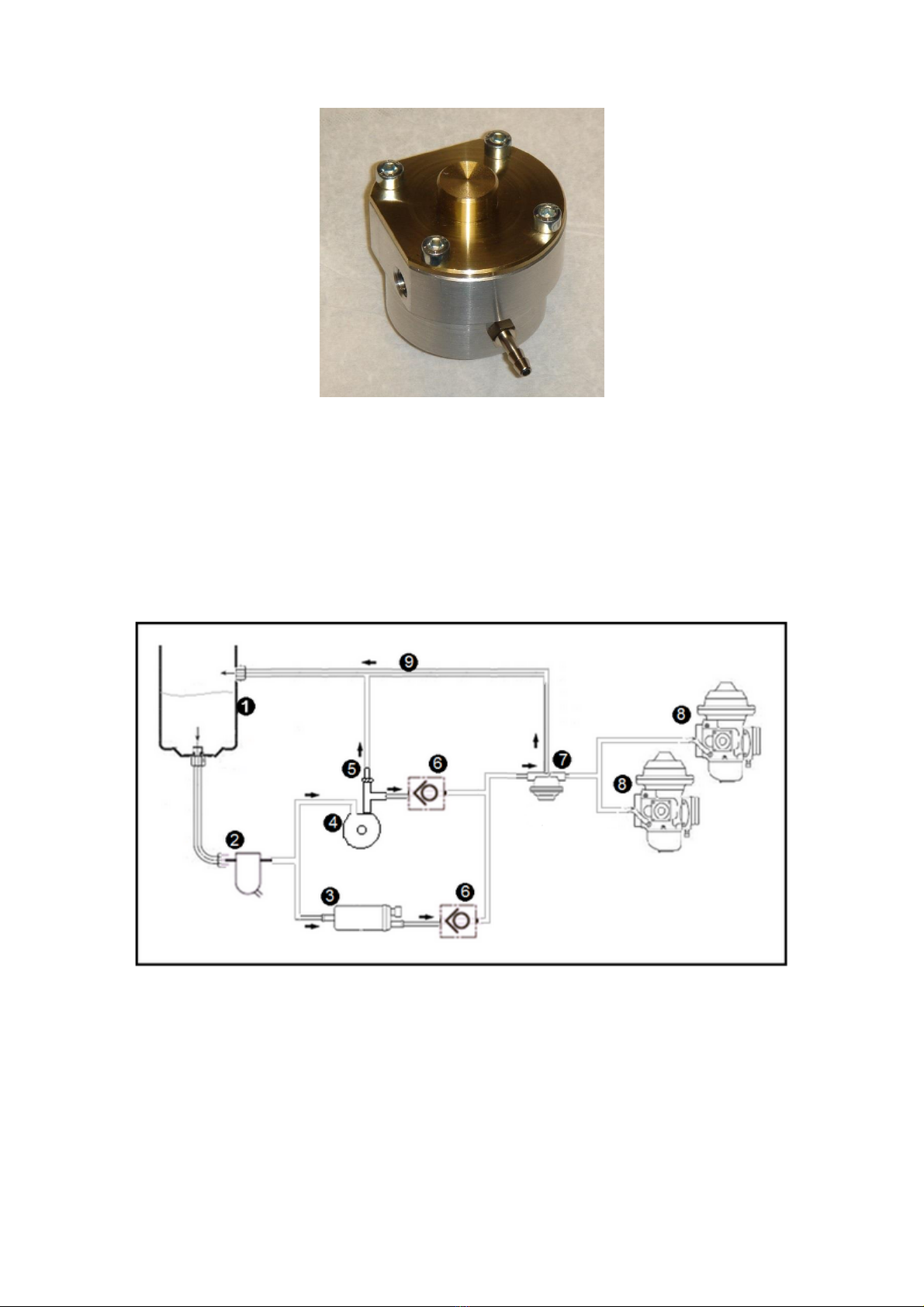
Example of installation scheme, work together electrical fuel pump:
1. Fuel Tank
2. Gascolator (filter and water trap)
3. Pierburg electrical 1bar Fuel pump
4. Flygas mechanical Fuel Pump
5. Optional: Restrictor Jet for air bubble (not plus of 1mm hole diameter)
6. Check Valves
7. Regulator Fuel Pressure
8. Carburattors
9. Fuel line return to tank (internal D. minimum 6mm)
19
Draft and possible run out of gasoline
Operation with low fuel in the tank or other operation that generates a air draft
from the injection pump (ex. caused by the shaking of the vehicle and then by the
oscillation of fuel in the tanks) leads to a sudden deterioration of the fuel pump
and the wear of the engine with the risk of possible breakage. In fact, the air
bubbles sucked do not come back in good percentage to the tank, but they must
be expelled through the injectors. (In a case of E.F.I. engine)
The disassembly and assembly of the mechanical fuel pumps MUST BE DONE
ONLY FROM FLYGAS. A disassembly of the pump without written authorization
from Flygas, lifts Flygas from any responsibility.
It is suggested to insert between tank and fuel pump a "Gascolator” (filter and
water decanter) with appropriately sized sections to separate presence of
moisture or water in gasoline and retain dirt in order to avoid the clog of the inlet
pumps filter.
Inspect frequently the cleanliness of the filter, considering that its eventual
blockage (because of the small total surface and the filtering fine pattern it may
happen), would reduce the passage of gasoline causing the wear of the engine
with the potential risk of breakage of the Oldham Joint and sudden turn off.
From the fuel pressure regulator to the tank
The fuel pressure regulator has an exit hole that returns to the tank to constantly dispose the
amount of exceeding gasoline. The connection pipe will have an internal section not less than 6
mm of diameter, if the length does not exceed 2 meters, otherwise we must increase the diameter
according to the increased length to re-establish the proper flow.
Use pipe and fittings of aircraft type (Aeroquip) resistant to 10 bar pressure and gasoline so called
" Green”, taking care that the connectors are mounted to the heads of the tubes in the correct way,
as indicated by manufacturer Aeroquip.
The return of the fuel must have a low resistance to the flow. From the pressure
regulator to the tanks the maximum tolerated pressure drop is 0.1 bar
Long periods of fuel pump inactivity or fuel pressure regulator can lead to a
deterioration of these elements and of their components. The downtime should
not exceed 30 consecutive days. The presence of water, even in very small
quantities, could irreparably damage the components compromising the function
of the complete system.

20
8. FIRST STARTING
Once the installation is completed, before the first starting is carried out, follow the instructions
below:
Recheck all the connections of the various pipes, gasoline and air.
Visually check that there are no electrical parts or pipes accidentally leaned (or very near)
against the engine exhausts since they reach within few seconds temperatures like 700/900
° C.
Visually check that there are no electrical parts or fittings leaned accidentally against sharp
edges.
Visually check that there are no electrical wires or pipes near the engine rotating parts.
Activate the fuel pumps and check that there are no leaks nor drips
Check that the carburettors butterflies are at the minimum (closed)
Adopt any other necessary precautions.
Proceed with the first starting (without propeller and with fly-wheel instead of propeller) with closed
accelerator in an open and proper place, away from people especially if not employees.
Whenever you turn the engine on without propeller it is necessary that a flywheel
must be installed in its housing; this flywheel must have the weight, the
dimensions and especially the moment of inertia similar to the propeller used, as
indicated by the engine manufacturer. Keep the throttle to minimum to avoid that
possible unusual revs could damage the engine.
After having completed all the controls to the minimum fix the plane in a fixed point, considering
that the propeller may develop a traction even of 250 / 300 kg. After having activated the brakes
and locked the plane, using wedges under the wheels or proper strings, simulate and check the
functionality of mechanical Fuel Pump, leave it work alone, with electrical fuel pump switch-off and
check the pressure and normal functionality of the engine
This manual suits for next models
1
Table of contents


