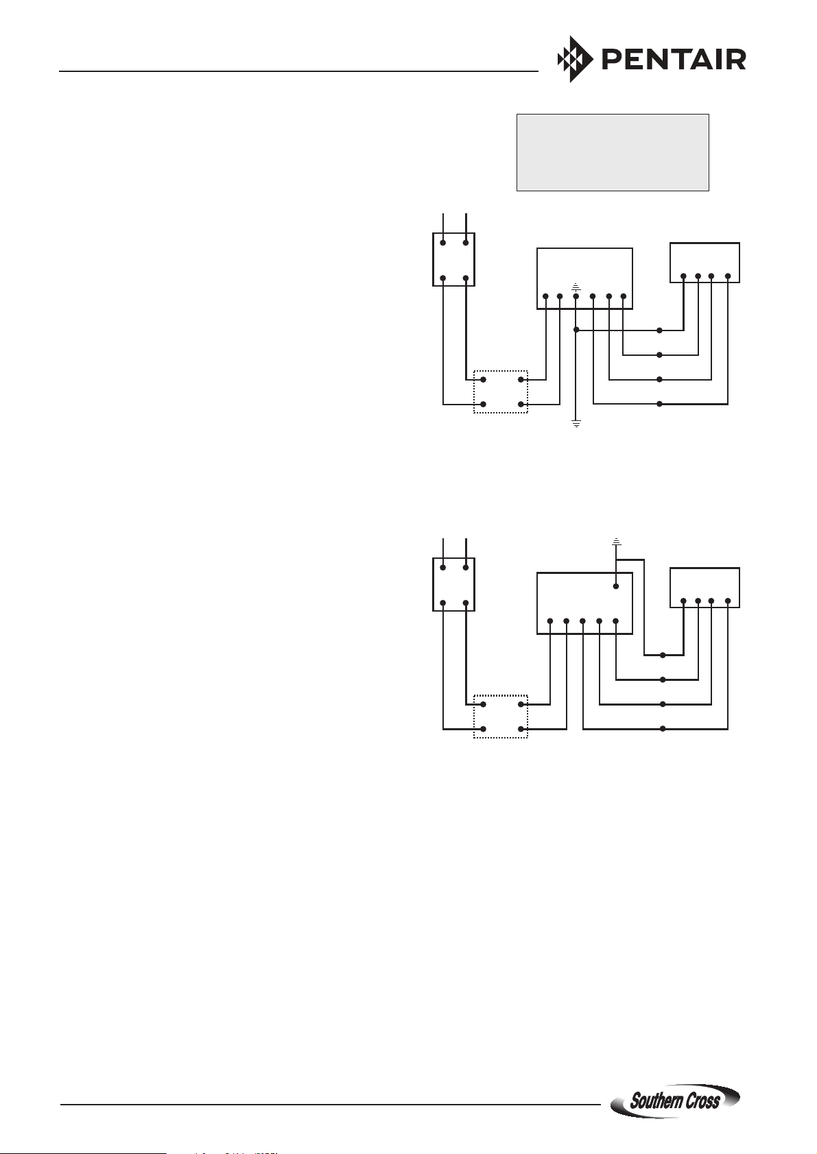
4. Remove cover fr om control box on magnetic starter. Do
not connect line voltage at this time. Connect cable to
control box. Make certain each lead is connected to the
proper terminal as indicated in the instruction on the control
box (also refer to the section on Wiring the Pump).
5. Submerge the pump in clean water in a test tank. Make
certain that the water is at least ve inches above the inlet
screen.
6. Make certain mains isolation switch is o. Connect line
from disconnect switch to control box. Turn on power at
mains isolating switch. Pump should start immediately.
Do not run pump at wide open discharge in test tank.
Throttle pump down with a gate valve.
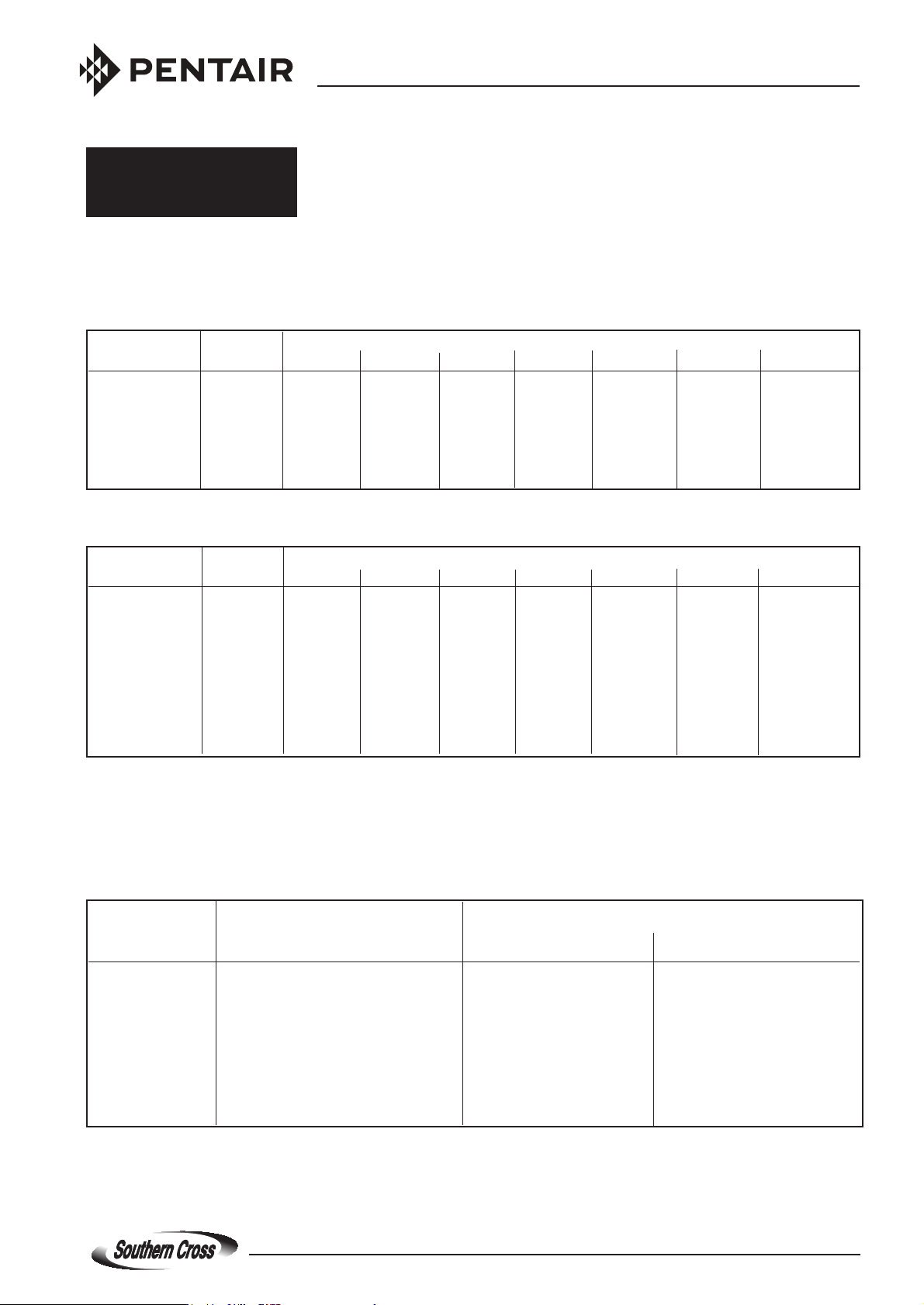
7. As soon as the unit is running, line current reading should
be taken and matched against those in the Cable Selection
Table. Run the pump only a few minutes in the test tank.
Stop. After one minute, start pump again.
8. If pump operates satisfactorily, turn o power at the mains
isolation switch. Disconnect power supply from the control
box and the control box from the pump cable.
9. Replace the pump in the shipping carton to protect it during
transportation to the bore site.
Installation in the Bore
1. Recheck the system's electrical ratings. If the cable has
been spliced, make certain that the colour code has been
followed.
2. If there is a possibility the water level will drop enough to
let air into the pump, a low water level electrode protective
relay must be tted to the starter. This can be either a manual
reset type (only two electrodes required) or an automatic
reset type (three electrodes required).
3. Attach rst section of pipe to pump and tighten. If plastic
riser is being used, nylon or stainless steel safety cable
must be attached to support the pump.
4. Connect a pipe vice or collar clamp rmly to the upper end
of the pipe to keep it from slipping and dropping into the
bore. Lower the pipe column into the bore. Do not lower
the unit by its electric cable. A nylon or stainless steel safety
rope may be attached to the pump to aid in lowering it.
NOTE : Where the riser pipe exceeds 100 metres, a non-
return valve should be installed to limit damage caused by
water hammer. This extra valve should be positioned halfway
up the riser pipe, and must always be incorporated if the
pump is being used to supply a pressurised system.
5. Lower the pipe into the well as each section is added.
Make sure that the pump is installed at least 3 metres (10
feet) above the bottom of the bore to prevent sediment from
covering the motor.
NOTE:Motor must be set above level at which water enters
the bore, or above bottom of casing or top of bore screen.
If this is not possible, a “cooling shroud” must be used.
Tape or clamp the electrical cable to the pipe at 3 metre
(10 feet) intervals, being careful not to cut the insulation.
The cable can be checked for insulation breaks as it is
attached to the pipe. Any damaged spots should be cleaned
carefully and repaired using self-amalgamating waterproof
tape or adhesive lined heatshrink tubing. Do not drag cable
over the bore casing or allow it to become pinched. At the
top of the last length of pipe, install a tee, which can be
used for lifting when adjusting the bore seal and when
making nal adjustment of the pump setting. A hose cock
can be installed temporarily for testing bore and pump
capacity.
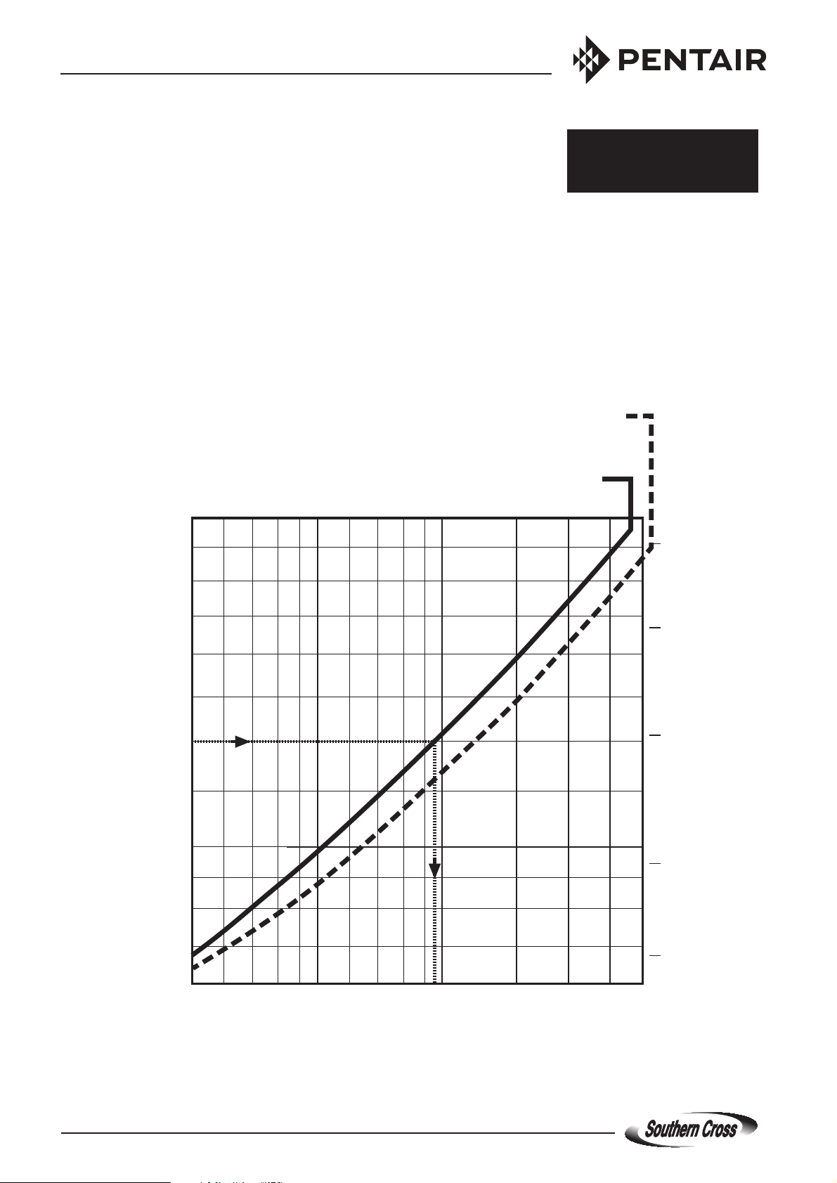
NOTE : For the motor to function correctly, a specic minimum
ow speed of water over the outside of the motor is
necessary.
(Refer to graph on page 8).
1 Submersible Pump 2 Contr ol Panel
3 Gate Valve 4 Pressure Gauge
5 Non-return Valve 6 Cut-o Device
7 Bore Screen 8 Bottom of Bore
9 Submersible Cable 10 Cable Clips
11 Bore Cap 12 Cooling Shroud
A. Water Level
B. Distance between Water Level & Pump
Outlet - Min. 4.5 metres
C. Distance from Bottom of Bore to Bottom
of Motor - Min. 3 metres
D. Distance between Motor and Bore
Screen (if applic.) - Min. 1 metre
“SC/SD” SERIES 4 Inch Submersible Pump Installation and Operation Manual
10
1
12
8
11
9
5
3
4
2
A
D
B
7
6
C
Page 2