Flymaster B1 NAV User manual

B1 NAV User manual
Document version 1.4

2009 FLYMAS ER Avionics Ltd.
R. Comendador Rainho, 192 - Apartado 118
3701-910 S. João da Madeira
Portugal
el: + 351 256 880 568
Fax: + 351 256 880 551
All rights reserved. Except as expressly provided herein, no part of this manual may be
reproduced, copied, transmitted, disseminated, downloaded or stored in any storage
medium, for any purpose without the express prior written consent of FLYMAS ER
Avionics Lda. herein FLYMAS ER avionics. FLYMAS ER Avionics hereby grants
permission to download a copy of this manual onto a hard drive or other electronic storage
medium to be viewed and to print a copy of this manual or of any revision hereto, provided
that such electronic or printed copy of this manual must contain the complete text of this
copyright notice and provided further that any unauthorized commercial distribution of this
manual or any revision hereto is strictly prohibited.
Information in this document is subject to change without notice. FLYMAS ER Avionics
reserves the right to change or improve its products and to make changes in the content
without obligation to notify any person or organization of such changes or improvements.
Visit the FLYMAS ER Avionics website (www.flymaster-avionics.com) for current updates
and supplemental information concerning the use and operation of this and other
FLYMAS ER Avionics products.
Document version: 1.4 Page 2

Warning
It is the sole responsibility of the pilot to operate the aircraft in a safe manner, maintain full
surveillance of all flying conditions at all times, and not become distracted by the Flymaster
B1nav. Flymaster Avionics is not responsible for any damages resulting from incorrect or
no data provided by the Flymaster B1 NAV. Flight safety is the sole responsibility of the
pilot.
It is unsafe to operate the Flymaster B1 NAV while in the air. Failure by the pilot equipped
with a Flymaster B1 NAV to pay full attention to the aircraft and flying conditions while
flying could result in accident with property damage and/or personal injury.
Document version: 1.4 Page 3

Table of Contents
1.Introduction........................................................................................................................ 6
1.1.Getting started........................................................................................................................ 6
1.2.B1 NAV Keys...........................................................................................................................7
1.3.Switching B1 NAV On and Off................................................................................................. 7
2. he Flight Mode Screen.....................................................................................................8
2.1.Status indicators Section......................................................................................................... 8
Battery Level Indicator.......................................................................................................... 9
Sound Level Indicator........................................................................................................... 9
Satellite Lock Status........................................................................................................... 10
2.2.Variometer Section................................................................................................................ 10
Analogue vario................................................................................................................... 10
Integrated vario................................................................................................................... 11
Maximum and Minimum Integrated vario............................................................................ 11
Gain in thermal................................................................................................................... 11
2.3. ime Section......................................................................................................................... 11
2.4.Altimeter and Speed..............................................................................................................12
2.5.User Defined Data Section.................................................................................................... 12
2.6.Navigation Section................................................................................................................ 14
3.Menu mode...................................................................................................................... 17
ask Delay.......................................................................................................................... 18
4.Waypoints and ask......................................................................................................... 19
4.1.Waypoint action menu........................................................................................................... 20
4.2.Edit task(route)...................................................................................................................... 20
Edit route point................................................................................................................... 22
Move Route Point............................................................................................................... 23
Remove Route Point.......................................................................................................... 23
Delete Route...................................................................................................................... 23
4.3.Example of a task and how to set it up on the B1nav:........................................................... 24
5.Near Airfields....................................................................................................................26
6.Flight Log......................................................................................................................... 27
7.GPS status....................................................................................................................... 29
8.Settings menu.................................................................................................................. 30
8.1.Set Altimeter.......................................................................................................................... 30
8.2. ime...................................................................................................................................... 31
Vario Integrator................................................................................................................... 31
rack interval...................................................................................................................... 31
8.3.Vario Acoustics...................................................................................................................... 31
8.4.Advanced Features............................................................................................................... 33
Damper...............................................................................................................................33
Cadence............................................................................................................................. 33
Dynamic Frequency............................................................................................................ 35
Buzzer................................................................................................................................ 35
Auto Silent.......................................................................................................................... 36
8.5.Screen contrast..................................................................................................................... 36
8.6.Language/Units..................................................................................................................... 37
8.7.Data fields............................................................................................................................. 38
8.8.FS Keys................................................................................................................................ 38
8.9.Firmware............................................................................................................................... 38
Document version: 1.4 Page 4

9.Miscellaneous.................................................................................................................. 40
9.1.Fail Safe firmware update..................................................................................................... 40
9.2.How to reset the B1 NAV.......................................................................................................40
Document version: 1.4 Page 5
1. Introduction
hank you for choosing FLYMAS ER B1nav. If you have any questions or comments
regarding the use of our vario you can visit our website or contact our Support
Department ([email protected]).
his manual covers Firmware versions up to 1.21h. If have a more recent version of
firmware some of the features may not be covered.
1.1.Getting started
Fully charge battery before using FLYMAS ER B1nav for the first time.
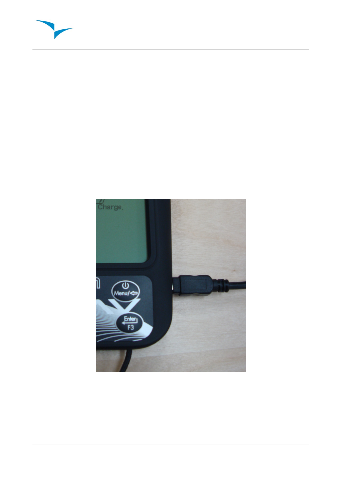
he battery may be charged by either connecting the B1nav's USB connector to the
wall socket charger or USB cable. B1nav's connector can be found on the right side of
the B1nav (see figure:1).
Battery charger connection (figure:1)
Please note that charging the battery using the wall socket charger is much faster using
a PC and respective USB cable, During the charging process the B1nav display “Quick
Charge” when connected to the wall socket charger and “Slow Charge” if connected to
the PC USB cable.
Document version: 1.4 Page 6

In “Quick charge” the battery should fully charge within approximately 3 hours, whilst in
“Slow charge” it may take up to 15 hours. Once the battery is fully charged the B1nav
will display “Complete” and stop charging.
B1nav uses a Lithium-ion polymer battery, which is not prone to “memory effect”,
herefore the battery does not need to be totally discharged before recharging. In fact,
in order to avoid battery degradation total battery discharge should be avoided.
1.2.B1 NAV Keys
B1nav keyboard (figure:2)
Four keys are used to interact with B1nav (see figure:2). Each key has 2 functions
depending on whether the device is in flight mode or in menu mode. Additionally the S1
key is used to “power-up” the B1 NAV when it is switched off.
In the flight mode Keys S2, S3 and S4 have user configurable functions F1, F2 and F3
that can allocated in the Menu->Settings->FS Keys. In menu mode all keys have fixed
functions represent by a symbol on the key.
1.3.Switching B1 NAV On and Off
o switch on the B1 NAV, briefly push the S1 key, this will display the start up screen
with a 10 second countdown . Pushing the S2 (Enter key) before the 10 seconds have
elapsed will initiate the B1 NAV On startup the B1 NAV will initiate in flight mode. If the
S2 key is not pushed the B1 NAV will go back to sleep.
o switch off the B1 NAV, push the S1(menu key) to activate menu mode, using the
arrow keys (S3 or S4) scroll the cursor to the “Shutdown” item and push the S2(Enter
Key).
Document version: 1.4 Page 7
S4 S2
S3 S1

2. The Flight M de Screen
he B1 NAV has a high resolution (320x240) and contrast display. his allows it to show
more useful information simultaneously.
In order to increase the usability of the device some of the information is dynamic. his
means the information can change according to the situation of flight. For example, if a
route is active and contains a start gate, the “Duration” field shows the “ ime to Go” up
to the point of start opening, after which it will show the duration of the flight.
he flight mode screen is divided into several areas called “sections”, see figure bellow:
Flight mode screen (figure:3)
2.1.Status indicat rs Secti n
In flight mode at the top of the FLYMAS ER B1 NAV screen, 3 symbols are visible
reporting the hardware status.
he 3 symbols from left to right are the Battery Level Indicator, Sound Level Indicator
and Satellite Lock Status.
Document version: 1.4 Page 8
ime
User defined data
Altitude/Speed
Vario
Navigation
Status indicators

•Battery Level Indicator
his symbol shows the status of the battery or charging indication.
Symb l Descripti n
•Battery level above 85%
•Battery level between 65% and 85%
•Battery level between 45% and 65%
•Battery level between 15% and 45%
•Battery level between 5% and 15%
•Less than 5% battery remaining
•Battery is charging.
•Battery not charging. his may be because of excess heat, the
B1nav's internal charge circuit will not charge the battery when
the battery temperature exceeds a 45ºC. Wait a while of try
moving the B1nav to a cooler location. If this status persists in
may indicate a problem with the battery.
•Sound Level Indicator
his symbol indicates the currently selected sound level (i.e. volume).
Symb l Descripti n
•Sound Level 3 (maximum sound level)
•Sound Level 2
•Sound Level 1
•Sound is muted (No sound)
Document version: 1.4 Page 9
•Satellite Lock Status
his indicator shows the number of satellites in use for calculating the current
position. When a 3D position can be obtained, usually when the GPS locks onto
more that 5 satellites, the indicator becomes highlighted.
As a general rule the more satellites that are locked the more accurate the
navigation solution. Note that FAI rules require 3D tracklog data, which includes
GPS altitude, therefore the B1 NAV will only start recording a tracklog when a 3d fix
is obtained.
he B1 NAV has very powerful 50 channel GPS receiver which offers unmatched
tracking performance in harsh signal environments (-160 dBm sensitivity), and very
short acquisition times. A differentiating factor of the B1 NAV is the 4 Hz GPS
update rate (others only provide 1Hz) which allows the B1 NAV pilot to see very
small speed and position changes. Furthermore, the movement of the position
arrow is smother and any position change is shown in ¼ of the time of other
devices. (4 Hz update rate requires more than 5 satellites in view).
More information about GPS accuracy and also other GPS related information can
be seen in (http://www.kowoma.de/en/gps/errors.htm).
2.2.Vari meter Secti n
he variometer section contains information about the rate of climb, it is comprised of
an analogue “instant” vertical speed indicator know as the Analogue vario and several
digital indicators providing information about averaged rates of climb.
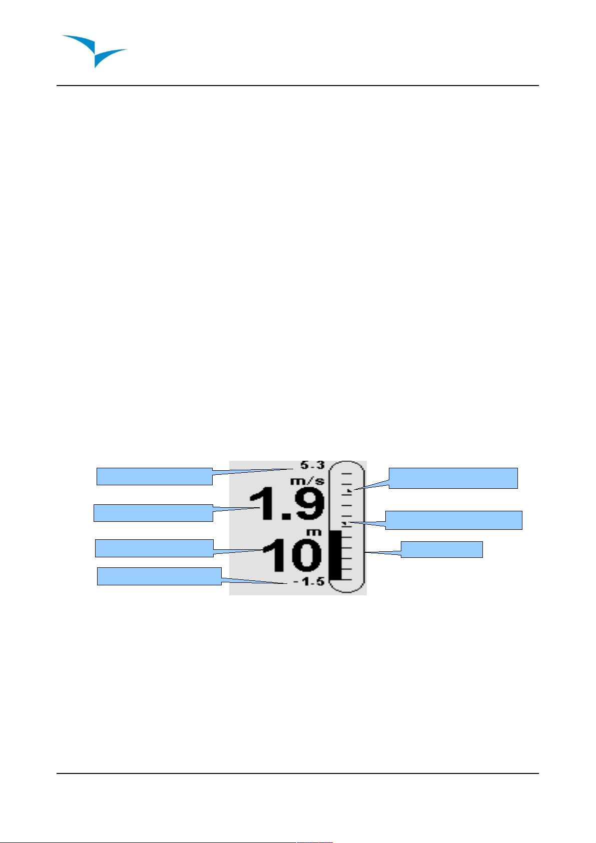
Variometer Section (figure:4)
•Analogue vario
he Analogue vario bar is scaled from 0 m/s to +/-10 m/s depending if you are
climbing or sinking.
When the B1 NAV detects that the pilot is climbing, a black bar starts to grow from
the bottom of the scale to the top ,and for each increase of 0,1 m/s the bar height
graph will increase to the maximum of +10m/s.
Document version: 1.4 Page 10
Max Integrated vario
Integrated vario
Gain in thermal
Minimum Integrated vario
Analogue vario
Maximum Climb indicator
Maximum Sink indicator

If a sink is detected the Bar will increase from the top of the scale to the bottom and
will increase for each 0,1m/s to a maximum of -10m/s.
he B1 NAV additionally graphically shows the values of maximum vario analog
sink and climb encountered during the flight. his information are represented by
two small arrows, the maximum analog vario climb is represented by a small arrow
pointing up, inversely the arrow pointing down represents the maximum sink.
•Integrated vario
his indicator displays the averaged rate of climb during the last X seconds. he
factory default for X is 10 seconds, but can be adjusted in the settings (see item
8.2. on page 35). he resolution of the digital vario is 0.10 m/s and the full scale is
reached at ±99.9 m/s.
he integrated vario is particularly useful in determining the actual strength of a
bumpy thermal.
•Ma imum and Minimum Integrated vario
Once a flight has started these indicators show the maximum and minimum thermal
strength encountered during the flight. Note that these values are using the
integrated vario not the instantaneous rate of climb, so they offer a good indication
of the quality of the day's thermals. When the B1 NAV is switched off these values
are reset back to zero.
•Gain in thermal
he B1 NAV considers a thermal has been entered when the Integrated vario value
goes above 0.5m/s and considers the thermal is exited integrated vario goes bellow
-1.0 m/s. Once in the thermal the Gain indicator will keep track of the maximum
altitude reached in the thermal. If the altitude is less than the the max thermal
altitude then a negative number will show the difference from the highest point
reached. If the altitude is equal or higher than the maximum reached then a positive
number will show the altitude gained since entering the thermal.
he thermal gain indicator is particularly useful in measuring the performance of a
thermal. ypically a thermal may have slow point (inversions) the unique gain
indicator keeps track of how much altitude is being gained in the thermal. When the
pilot enters the thermal B1 NAV will reset the Gain indicator to 0 and will start to
track how much altitude the pilot has gained. At a certain point in the thermal the lift
may become weaker and inconsistent. At this point the gain indicator will show
altitude loss in this inconsistency. Once the pilot cores the thermal correctly again
the indicator will show the gain since thermal start.
2.3.Time Secti n
he Time Section contains 2 fields, the actual local time and an elapsed time or time
remaining. hese fields are represented in Hour:Minute:Second format.
Document version: 1.4 Page 11

All the internal B1 NAV time calculations are based on U C (Coordinated Universal
ime). his is also the time saved on the track-log. However, the time displayed in the
time field is calculated adding an U C offset to the U C time obtained from the GPS
receiver. he “U C offset” should be defined in the settings menu (see item 8.2. on
page 35) so that the correct local time is displayed.
he second time field is dynamic and will vary according to the current flight status and
type of task defined. It will show G (time to go) before start gate opening, and will
then change to “Dur” (duration) which is the time elapsed since the opening of the start.
If no start gates are defined in the task or no task is defined then this field will show
“Dur” which in this case is the time elapsed since takeoff. he takeoff is event is
triggered when ground speed exceeds 10km/h and a 3d fix is available.
2.4.Altimeter and Speed
•Altitude
he “altitude” field (see Figure 6) indicates the absolute height in meters or feet
depending on the setting. his altitude corresponds to the barometric altitude and
thus depends totally on the QNH (absolute pressure at a given moment and
location in regards to the correspondent pressure at MSL).
he altimeter cannot be reset, but can be set using the corresponding menu option
(see item 8.1. on page 34).
•Speed
he “speed” field indicates the speed over ground in km/h. he speed is only
available when the GPS receiver has a valid signal.
2.5.User Defined Data Secti n
he B1 NAV has 6 user defined fields which the pilot can configure for his own needs
(see item 8.7. on page 40).
he following table lists and explains the available data fields, as the B1nav firmware
evolves this list will likely grow.
Document version: 1.4 Page 12

Field ID Descripti n
VMG Velocity made good, is the speed at which the pilot is approaching the
active turn point.
Dist off Distance to take off. he direct distance to the point of take off.
Dist Start Distance to start. he distance to the start cylinder line.
Dist.Goal Distance to goal. From the current position and flying through all
pending turnpoints.
Speed Strt Speed to Start. he speed at which the pilot must fly in order to reach
the start gate at its opening.
G.R.Goal Glide ratio to goal. Indicates the glide ratio (finesse) from the current
position and altitude to the Goal going through the remaining turn points.
Cur G.R. Current glide ratio. his glide ratio is calculated from the integrated vario
over the current ground speed.
G.R.M.G Glide ratio made good. he actual glide ratio towards the active turn
point. It is calculated using the integrated vario over the VMG.
A.OverGoal Altitude over goal, is the difference in altitude from the current altitude to
the goal's altitude. Based on barometric altitude.
Max.Alti Maximum altitude of reached during current flight. his is based on
barometric altitude.
GPS Alti Altitude reported by the GPS.
Alt Gain Altitude gained in current thermal.
Land in During competitions tasks it is common, usually due to safety reasons to
have a “land by” time. he land by time if defined by adding a waypoint
typically the goal to the already defined task, setting it as "Landing" and
defining the time. “Land in” shows the amount of time remaining before
having to be on the ground.
Goal close he time remaining to goal close time.
Altitude2 Second Altimeter which can be set independently of the main altimeter.
Vario Numeric value of the instant Vario value.
Arrival Next Estimated arrival height above to next waypoint. he height is calculated
considering the average glide ratio the pilot has being made.
Arrival Goal Estimated arrival height above the Goal. he height is calculated
considering the average glide ratio trough each of the remaining task
legs. his means that wind, day quality and glider performance is
integrated into calculation.
Dist. Edge Distance to the optimal tangent point of next waypoint. (see section 2.6)
Above off Altitude above takeoff, this field is automatically calculated since the
B1nav remembers the takeoff altitude when it sees the pilot launch.
Document version: 1.4 Page 13

Field ID Descripti n
G.R. off Glide ratio to takeoff, usefull to know if you want to top-land.
Dist. hermal Distance to last thermal core.
Heading Pilots heading in degrees.
Ave.Speed Average speed, uses a filter to show a smoother speed number,
eliminating erratic speed jumps due to glider pitching.
Wind Speed Calculated wind speed using drift calculations. his figure is also shown
next to the “Navigation wheel”.
Document version: 1.4 Page 14

2.6.Navigati n Secti n
Navigation section (figure:5)
his is B1 NAV main navigation information section. It shows graphically which direction
to navigate, the actual travel direction, wind direction, next waypoint, start gate/goal
distances and thermal core map.
For information to be displayed in the navigation section the B1 NAV must have a valid
GPS fix. When no valid fix is available the direction arrow will not be shown and the
distance indicators will show “-----”.
When a route is active the “direction of next point” arrow (bigger one) will point to the
optimal cylinder tangent point. If no route is defined it will start showing the direction to
the takeoff after the takeoff is detected, i.e. the average speed exceeds 5km/h. During a
competition task flight using the optimal tangent navigation saves a substantial amount
of time. he smaller arrow points to the center of next waypoint cylinder, the
combination of both arrows provides a spatial location of the turnpoint.
he example bellow shows a hypothetical task. A pilot using navigation to the center of
the turnpoints will probably be flying the blue course, whilst a pilot using the optimized
route will fly the substantially shorter red route.
Document version: 1.4 Page 15
Direction of travel
Fine adjustment indic.
Wind direction
Distance to next point
Direction to optimal cylinder
tangent point
Distance start/goal
Direction to center of next point
hermal Core indicator

Navigation wheel (figure:6)
As the correct course approaches it becomes difficult to understand which is the perfect
direction, so B1 NAV shows a “fine adjustment indicator” in the form of a small arrow. An
arrow to the left means the pilot should turn slightly to the left, and inversely an arrow to
the right indicates a small adjustment to the right is needed.
When the course is perfect, i.e. less than 1º off, B1 NAV indicates this by showing a
large arrow forward, see figure:7 bellow.
Perfect heading (figure:7)
he 2 fields bellow the navigation wheel show the distance to go for next active turn
point and a dynamic field showing either the distance to the start gate or the distance
remaining to the goal depending on whether the start has been validated or not.
Document version: 1.4 Page 16

A start is automatically validated when a pilot correctly completes the start, until the start
is completed B1 NAV will not advance to the next point in the route. Another important
aspect of the start is B1 NAV does not point to the start cylinder but rather to the next
turn point on the list.
he distance to start will become highlighted when the pilot is in an irregular position,
i.e. inside a start cylinder where he should be out or vice-versa.
•Thermal Core Map
Another useful feature of the B1-NAV is the thermal core map. During a thermal climb
the B1-NAV keeps track of the strongest climb values point for each 50m layer. he
point of strongest lift is then graphically represented by a black ball on the Navigation
Wheel, showing where the thermal core is relative to the pilot's position. he position of
the ball (thermal core) is constantly updated as the pilot moves. When the pilot is over
140m from the thermal core the ball will be at the edge of the circle, as he moves closer
it will move towards the center.
In the image below (figure:8) the thermal core is currently behind the pilot at a distance
of approximately 80 meters.
ermal core map(figure 8)
Document version: 1.4 Page 17

3. Menu mode
When in the flight mode screen, pushing the menu(S1) button accesses the menu
mode screen. When in the menu pushing the menu(S1) button will go back to flight
mode.
Main menu (figure:9)
o access the different items on the menu use the arr w up(S3) and arr w d wn(S4)
buttons. Once a menu item is selected pushing the enter(S2) executes the selected
function.
Menu item Descripti n
Waypoints/ ask Accesses B1 NAV's waypoints and task definitions. (see item
4. on page 20)
ask delay Shifts all time data in the active task.
Near Airfields Displays airfields page, dynamically shows the glide ratios and
distances to the nearest landing fields, sorted by easiest glide.
Flight log Accesses the stored flights list.
GPS Displays detailed GPS status and allows GPS module reset.
(see item 7. on page 32)
Settings Accesses the Settings sub menu. (see item 8. on page 33)
Shutdown Switches off the B1 NAV, and displays detailed battery status.
Document version: 1.4 Page 18

•Task Delay
During competitions it is common practice due to weather conditions to postpone a
task. Generally take off is postponed and so is the start gate, goal close and land by
times. Instead of having to edit the defined task B1 NAV offers a task delay feature
which moves all defined times in a task forward by X minutes. o delay a task in the
menu simply push the enter(S2) key on the ask delay option, using the arrow keys
(S3 and S4) select the number of minutes to delay by and push the enter(S2) key.
o exit the “ ask delay” function without changing task times push the menu(7) key.
Document version: 1.4 Page 19

4. Waypoints and Task
he Waypoints/ ask page manages the waypoints and task definition in the B1 NAV.
Waypoints/ ask page (figure:10)
he page is divided into 3 areas, the waypoint list, task and selected item data. On
entering the page the cursor is active on the waypoint list, and the selected item data
will show details about the selected waypoint. As the cursor is moved to a different
waypoint so the selected item data changes as to show details of that waypoint. If no
waypoints are defined the waypoint action menu is automatically opened and the only
available option is the “Insert new Waypoint”.
Pushing the enter(S2) on the selected waypoint opens the waypoint action menu in the
selected item data area (see figure 11). Pushing the menu(S1) goes back to the main
menu.
Document version: 1.4 Page 20
Selected item data
Waypoint list
ask
Table of contents
Other Flymaster Accessories manuals


Popular Accessories manuals by other brands


Nice
Nice Nemo WSCT Instructions and warnings for installation and use

netvox
netvox R712 user manual

VWR International
VWR International 1575 Installation and operation manual

Arista
Arista ALC-DH-BT installation instructions

Contours
Contours Carrycot V2 ZY070 manual

Marquant
Marquant 444-015 User instructions