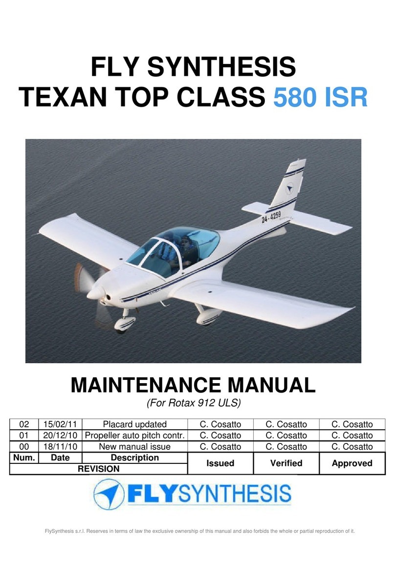
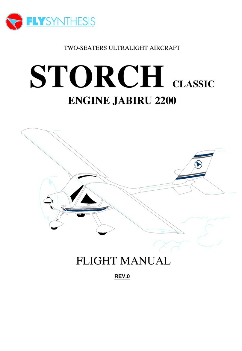
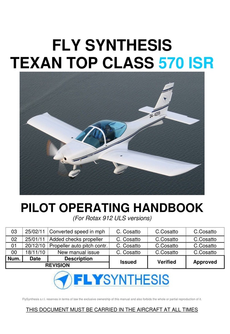
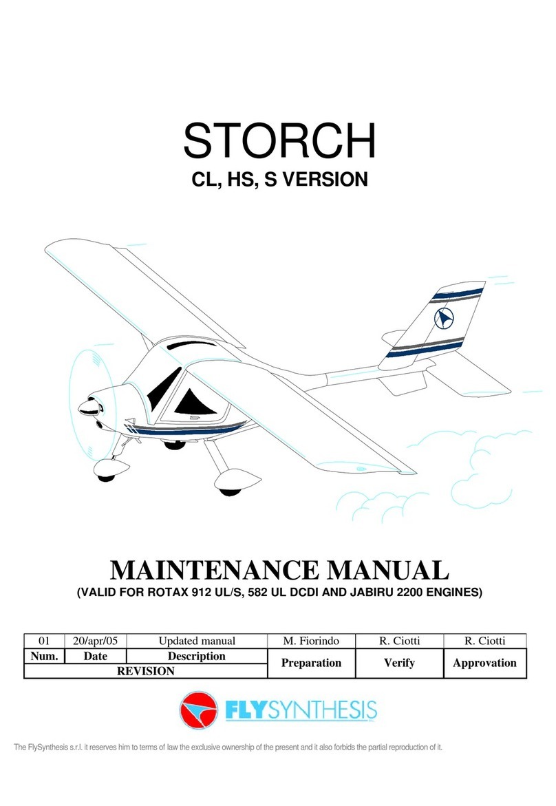
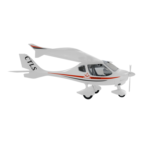
FlySynthesis Wallaby User manual

MAINTENANCE MANUAL
TWO SEATERS ULTRA LIGHT
WALLABY
EQUIPPED WITH:
ROTAX 503
ENGINE

FLYSYNTHESIS WALLABY SECTION VIII
MAINTENANCE MANUAL
English Edition 2003-03-28 Page VIII-2
3.1 LOG OF REVISIONS
All revisions to this Maintenance Manual must be recorded in the following table.
Revision Number Revision Highlight and Pages affected Date Signature

FLYSYNTHESIS WALLABY SECTION VIII
MAINTENANCE MANUAL
English Edition 2003-03-28 Page VIII-3
MAINTENANCE manual
TABLE OF CONTENT
Paragraph Page
3.1 LOG OF REVISIONS 2
MAINTENANCE MANUAL 4
3.2 INTRODUCTION 4
3.3 SCHEDULED MAINTENANCE4
3.4 AIRPLANE PREPARATION FOR FLIGHT 5
REFUELING 5
FUEL DRAINING 5
PRE FLIGHT INSPECTION5
3.5 DETAILED SCHEDULED INSPECTIONS 8
3.6 TORQUE FOR BOLTS AND NUTS 13
3.7 MAINTENANCE PER PERIOD OF TIME 13
SCHEDULED INSPECTION 13
TIME LIMITED COMPONENTS 13
3.8 NON SCHEDULED MAINTENANCE 13
HEAVY LANDING 13
DAMAGE TO THE COMPOSITE STRUCTURE 14
EXCEEDING ENGINE LIMITS 14
PAINTING THE AIRPLANE14

FLYSYNTHESIS WALLABY SECTION VIII
MAINTENANCE MANUAL
English Edition 2003-03-28 Page VIII-4
MAINTENANCE MANUAL
3.2 INTRODUCTION
In order to maintain the airplane in an airworthy condition, to enjoy a safe flight and
save on repair expenses, maintenance tasks must be carried out.
Maintenance instructions are divided to scheduled and non-scheduled tasks.
Scheduled tasks are carried per time, either flight hours or period, like once a year.
Non-scheduled tasks are per airplane condition after damage is discovered or some
unusual happening like a heavy landing.
3.3 SCHEDULED MAINTENANCE
Scheduled maintenance is composed of the following:
Preparation of the airplane for flight includes refueling, fuel system draining and pre
flight inspection.
Scheduled inspections per flight time are planed in a cycle of 50 flight hours, to match
the engine manufacturer requirements, these are composed of the following
inspection types: 25 hours inspection; 50 hours inspection; 100 hours inspection and
200 hours inspection.
The normal cycle repeats itself per following table:
Flight Time 25 50 100 150 200 250 300 350 400
Inspection Type 25 50 100 50 200 50 100 50 200
Flight Time 450 500 550 600 650 700 750 800
Inspection Type 50 100 50 200 50 100 50 200
Flight Time 850 900 950 1000 1050 1100 1150 1200
Inspection Type 50 100 50 200 50 100 50 Overhaul
The 25 hours inspection should be carried out only once after the first 25 flying hours
of the airplane. It is also done once after an engine change, engine or airplane
overhaul or major repair due an accident or other major damage.
Scheduled maintenance per period is done after one year or two years, if the airplane
did not reach certain time of flight.
Other limited periods for certain equipment are listed separately.

FLYSYNTHESIS WALLABY SECTION VIII
MAINTENANCE MANUAL
English Edition 2003-03-28 Page VIII-5
3.4 AIRPLANE PREPARATION FOR FLIGHT
REFUELING
Magnetos OFF check
Master switch ON
Fuel quantity check
Master switch OFF
Fill the required amount of fuel per flight plan
Master switch ON check
fuel quantity
Master switch OFF
Record amount of fuel in airplane log
FUEL DRAINING
Fuel drainage should be carried out once a day before the first flight, and 10 minutes
after each refueling of the tank. Fuel drainage should also be repeated if the airplane
was parked for more than three hours.
CAUTION
Before attempting any service or inspection on the airplane, check that the Magnetos
and Master Switch (key) are OFF
Use transparent container to drain into. If water is found in the drained fuel, repeat
fuel drain operation.
Fuel drainage should be performed before moving the airplane from it’s parking place,
to avoid condensed water present on tank Bottom to emulsify with fuel.
PRE FLIGHT INSPECTION
The pre flight inspection should be carried out BEFORE EACH FLIGHT, even if the
previous flight was very short. The pilot should carry out the inspection.
The inspection does not require any tools; only a clean rag is needed. It is important
to verify by sight and touch that there are no failures, defects, excessive clearances
or play.
For the detailed Pre Flight Inspection see Section IV of the AFM.
If a Daily Inspection was just completed, pre flight Inspection is not required.

FLYSYNTHESIS WALLABY SECTION VIII
MAINTENANCE MANUAL
English Edition 2003-03-28 Page VIII-6
Nose wheel
Axle locking nuts check tight
Tire and wheel undamaged, inflated properly.
Gear strut no distortion.
Gear support frame locking nuts tightened no distortion.
Propeller
Blades and hub undamaged and cleaned.
Spinner undamaged, fixed tight
Engine
Exhaust and mufflers no damaged or cracks, retaining spring hooked,
Fuel pipes undamaged.
Electric and ignition line undamaged.
Throttle and choke function properly, smooth movement
R.H. main landing gear
Strut no distortion, locking nuts tightened, and visible
welding no cracks is evident
Tire undamaged, inflated properly
R.H. wing
Skin undamaged-absence of swellings and depressions,
no delamination
Wing-fuselage top fairing secure.
Airspeed probe undamaged, aligned, pressure tubes securely
connected
Leading edge undamaged,
Wings tip undamaged, fixed tight
Trailing edge undamaged
Aileron undamaged, freedom of movement, no excessive
hinge slack, all split pins in place hinges securely
connected to the wing, balance weight fixed tight, no
play
R.H. Fuselage
Skin undamaged, no sign of swellings or delamination
Tail
Vertical fin undamaged, no depressions or delamination,
Rudder structure and skin undamaged, hinges secured
Lower the aircraft tail in order to lift the nose wheel from the ground, check rudder
free movement, no play on lower hinges.
Control cables secured, freedom of oscillating eye-ends.
Balance weights fixed tight, no play

FLYSYNTHESIS WALLABY SECTION VIII
MAINTENANCE MANUAL
English Edition 2003-03-28 Page VIII-7
Elevator (Stabilator)
Structure and skin undamaged, no delamination, leading edge. Attached
firmly through out its length
Elevator free movement up and down
Elevator hinge plate undamaged, attached firmly, no play
Balance weights fixed tight, no play
Hinges pins tight and safe tied
Trim tab undamaged, attached properly, correct operation.
L.H. Fuselage
Skin undamaged, no sign of swellings or delamination,
Inspection doors closed
L.H. wing
Skin undamaged-absence of swellings and pressings, no
delamination
Leading edge undamaged,
Wings tip undamaged, fixed tight
Trailing edge undamaged
Aileron undamaged, freedom of movement, no excessive
hinge slack, all split pins in place hinges securely
connected to the wing, balance weight fixed tight, no
play
L.H. main landing gear
Strut no distortion, locking nuts tightened, and visible
welding no cracks is evident
Tire undamaged, inflated properly
Fairing undamaged, fixed tight and clean.
Cockpit checks
Instrument panel fixed tight,
Master switch (key) ON all instruments operate as required
Master switch OFF instruments indicate zero or as required
Control sticks control rods connected securely (visible part only)
free and full movement
Rudder pedals no distortion, rudder and nose wheel aligned,
nose wheel control rods and rudder control cables, securely attached, condition,
spring centering cables condition
Throttle and choke free and smooth movement, installed securely
Brake lever brake lever operates smoothly, correct feel.
Trim lever installed securely, smooth movement
Seat belts undamaged, locking device locks and releases freely
Seats Fixed.
Windshield clean, fixed securely
Weight and balance calculate.
Aircraft log book record the Daily Inspection in the book.

FLYSYNTHESIS WALLABY SECTION VIII
MAINTENANCE MANUAL
English Edition 2003-03-28 Page VIII-8
3.5 DETAILED SCHEDULED INSPECTIONS
SCHEDULED INSPECTIONS –PROGRAM INSPECTION
TYPE
TASKS TO BE PERFORMED
25
50
100
200
general
Ensure that ignition switches are OFF and master switch
(key) is REMOVED XXXX
Remove seats and seat back XXXX
Remove fuselage –wing top fairing XXXX
Check all rivets to detect loose rivets. Any loose rivet shall be
replaced with oversize rivet XXXX
propeller
Inspect the prop blade for crack, stone blow and other Defect,
small defect smooth with fine glass paper and Apply lack XXXX
Check propeller bolts tightness, Torque 15 Nm, check safe
tying if required. XXXX
fuselage
Inspect fuselage for condition and other sign of defect. Check
skin for delamination, inner structure bulkheads to be glued to
skin with no cracks or separation
XXXX
Check main landing gear frame (steel tube spar) for
condition, no cracks. Four areas of connection to fuselage
structure, no delamination or skin separation, bolts and nuts
tightness
XXX
Check wing connection for bolts tightness, no cracks XXX
Front windshield, clean and check condition, check
Attachment to the structure XXXX

FLYSYNTHESIS WALLABY SECTION VIII
MAINTENANCE MANUAL
English Edition 2003-03-28 Page VIII-9
TASKS TO BE PERFORMED
25
50
100
200
Flight controls
Check aileron surfaces for condition, smooth and free
movement, no play up or down, side play acceptable. XXXX
Check bolts and nuts attaching the aileron hinges for
tightness. Check hinge pin tightness XXXX
Check elevator surface for condition, smooth and free
movement, and no play up or down. XXXX
Check bolts and nuts attaching the elevator support plate
mechanism for tightness, no play. XXXX
Check rudder control surface for condition, smooth and free
movement, no side play, XXXX
Check bolts and nuts attaching the rudder hinges for
tightness, no play. XXXX
Check aileron push pull rods and rod ends for condition no
distortion, free clearances all around in full movement XXXX
Check elevator flex-ball push-pull cables and ends for
condition no distortion, free clearances all around in full
movement.
XXXX
Check rudder control flexible push-pull cables and cable ends
for condition, replace if necessary. XXXX
Check trim lever for secure installation. XXXX
Check trim cable for condition, smooth and free movement,
end connections. XXXX
Check trim surface for secure installation XXXX
Check ailerons surface angles both left and right sides, XXX
Check elevator surface angles, XXX
Check rudder surface angles, left and right XXX
Check anti-servo-tab surface angles, XXX
Check trim surface angles, XXX
Lubricate lightly all movable part and hinges. XXXX
Check tightening of nuts securing aileron hinges (support
plates) in wings. XXX
Check tightening of self-locking nuts securing the aileron
control rod end ball joints (fuselage/ wing). XXX
Check aileron push pull rods support in fuselage for tightness
of nuts. XXX
Wing
Check for loose rivets In wing tip connection upper and lower
surface, XXXX
Inspect wing surfaces condition for defect, no delamination or
scratches XXXX
Check fuel tank and outlet for security and leaks. Check the
fuel lines from and to the tank to engine for condition and
support.
XXXX

FLYSYNTHESIS WALLABY SECTION VIII
MAINTENANCE MANUAL
English Edition 2003-03-28 Page VIII-10
TASKS TO BE PERFORMED
25
50
100
200
Cockpit
Carefully inspect all operating levers for damage, wear,
abnormal play and security of attachment. Clean and lubricate
as required.
XXXX
Check electric wiring and electric component installation, for
condition and attachment XXXX
Clean the floor XXXX
Inspect pilot seat belts. Check operation of locking
mechanism. Check bolts and nuts securing the seat belts. XXXX
Check instrument panel and instruments attachment. Check
instruments connection, static and dynamic line. XXXX
Drain static and dynamic line. XXXX
Check windshield, no scratches or damage. Clean it. XXXX
Landing gear
Check nose landing gear structure for cracks and alignment,
attachment and bolt tightness. XXXX
Disassemble nose gear strut, check attachment of nose gear
to strut, reassemble, check bolts tightness. XX
Check nose wheel and tire condition. Inflation pressure
17.2 psi (1.2 bar). XXXX
Support the aircraft. Remove the main landing gear wheels
and check the brake linings for wear. Replace lining if
necessary.
XXXX
Remove the main landing gear RH and LH struts. Clean the
strut housings in the tubular framework. Clean the axle
assemblies. Lubricate strut housings for corrosion prevention.
Replace struts with 300 hours. Check struts for linearity.
XX
Reinstall the main landing gear struts and check the nuts for
tightness, both to wheel axle and to frame. XX
Check main landing gear RH and LH struts installation on
fuselage for tightness and safe tying. XXXX
Check self-locking nuts for tightening XX
Check brake system condition, replace if necessary. Check
brake self-locking nuts for tightness. XXXX
Check wheel and tire condition. Inflation pressure 32 to 35 psi
(2.2 to 2.4 bar). XXXX
Reinstall the wheels. Check nut for tightness, safe tying XXXX
Ensure that wheel bearings are not noisy and turn free and
smoothly without play. XXXX
Check main wheel alignment. XXX
Install strut XXXX

FLYSYNTHESIS WALLABY SECTION VIII
MAINTENANCE MANUAL
English Edition 2003-03-28 Page VIII-11
TASKS TO BE PERFORMED
25
50
100
200
Engine
All Engine maintenance is to be performed according to
ROTAX Maintenance manual
This maintenance schedule covers only the airframe
manufacturer installation in the engine compartment
XXXX
Check the fuel lines in the engine compartment for condition
and secure attachment. Replace if necessary. XXXX
Remove and clean the fuel filter. XXXX
Check throttle and choke control cables for proper installation,
tension and Interference with other equipment. Full free
smooth movement. Clean and lubricate the cables
XXX
Check the carburetors for leaks and proper adjustment, clean
if necessary. XXX
Clean the carburetors XX
Replace or clean the air filter per ROTAX instructions. XXX
Inspect carburetor-mounting flange for leakage. XXX
Replace carburetor-mounting flanges. X
Using a 10X magnifying glass inspect all welding of the engine
mount for cracks. Check for distortion. XX
Check for proper torque of the nuts securing the engine to the
engine mount. XXX
Check for proper torque the self-locking nuts securing the
Shock absorbers to the engine mount and supporting plate of
shock adsorbed to ribs.
XXX
Check the nuts securing the exhaust pipe XXX
Check all exhaust system for gas leaks, cracks, and
serviceability of retaining spring and rubber buffers. XXXX
Replace exhaust system-retaining springs X
Replace the 2 Muffler buffers. X
Check all the electrical system wiring in the engine
Compartment. XXXX
Check engine for leaks.XXXX
Check all fuel hose connection for security. XXXX
Check all components attached in engine area/compartment
for security. XXXX

FLYSYNTHESIS WALLABY SECTION VIII
MAINTENANCE MANUAL
English Edition 2003-03-28 Page VIII-12
TASKS TO BE PERFORMED
25
50
100
200
Check instrument pick-up attachments to engine for proper
condition. XXXX
Check all electric harness for proper condition. XXXX
Check the electrolyte level in the battery, add if required XXXX
Check battery base and securing straps for condition,
attachment and cleanliness from battery fluids. Look for
evidence of electrolyte leak.
XXXX
Check battery cables. XXXX
Check engine mount vibration pads and the proper torque of
the attaching nuts XXXX
FINISHING
Check if all the tools were removed from the airplane. XXXX
Close all inspection panels in the fuselage and wings. XXXX
Clean the cockpit XXXX
Install seats and seat backs. XXXX
Install fuselage-wing top fairing. XXXX
Check if all system, operate properly. XXXX
Refuel the tank and drain. XXXX
Run the engine. XXXX

FLYSYNTHESIS WALLABY SECTION VIII
MAINTENANCE MANUAL
English Edition 2003-03-28 Page VIII-13
3.6 TORQUE FOR BOLTS AND NUTS
Use the required torque of the different assemblies in the airplane.
Bolts used on airplane are galvanized of 8.8 class.
The requirement for this type of bolts is:
Diameter Tightening force applied Nm (kgm)
M5 4,1 (0,42)
M6 7,4 (0,75)
M7 15 (1,5)
M8 24 (2,4)
M10 45 (4,6)
3.7 MAINTENANCE PER PERIOD OF TIME
Scheduled inspection
If the airplane does not reach 100 flight hours within consecutive 12 months, a 100
hours inspection must be carried out before renewal
of its permit to fly.
If the airplane did not reach 200 flight hours within 24 months, a 200 hours inspection
must be carried out.
Time limited components
The following components must be removed for inspection and complete overhaul
after the time specified have expired:
Engine ROTAX 503 300 hours, or 10 years, whichever comes first, see
ROTAX manual
Propeller see propeller manual supplied with the propeller
Main landing gear strut replace at 300 hours
Engine exhaust retaining springs replace at 200 hours
Engine exhaust muffler buffers replace at 200 hours
3.8 NON SCHEDULED MAINTENANCE
HEAVY LANDING
1. A heavy landing event should be recorded in the airplane logbook by the pilot
or technician observing landing gear damage. Following inspection must be
carried out:
2. Check nose-landing gear structure for cracks and alignment, attachment and
bolt tightness.
3. Support the airplane, remove main landing gear wheels, check axle welding,
and check struts for linearity scratches and cracks. Replace struts if bent or
damaged.
4. Install wheels, Check main wheel alignment.
5. Check engine mount for distortion.

FLYSYNTHESIS WALLABY SECTION VIII
MAINTENANCE MANUAL
English Edition 2003-03-28 Page VIII-14
DAMAGE TO THE COMPOSITE STRUCTURE
Consult factory for more information
EXCEEDING ENGINE LIMITS
Any time an engine limit is exceeded, RPM, time limit, pressure or temperature,
record the event in the airplane logbook and consult the ROTAX Maintenance
Manual.
PAINTING THE AIRPLANE
The airplane when delivered is painted white all over.
It is prohibited to paint the upper surfaces of the wings and fuselage with any dark
paint, as this will increase the heat absorption from the sun, which may lead to
damage to the composite material structure.
Note
Consult the airplane manufacturer before painting the surfaces.
Table of contents
Other FlySynthesis Aircraft manuals

