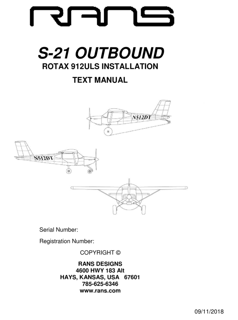
Rans S-21 OUTBOUND User manual

09/11/2018
S-21 OUTBOUND
TEXT MANUAL
Serial Number:
Registration Number:
COPYRIGHT ©
RANS DESIGNS
4600 HWY 183 Alt
HAYS, KANSAS, USA 67601
785-625-6346
www.rans.com

09/11/2018
RANS S-21 OUTBOUND TEXT MANUAL 1
ASSEMBLING THE MANUAL
1. Obtain three 2" wide 3-ring binders.
2. Place the TEXT, PARTS and FIGURES manuals in separate binders. Every
page has a section number then a page number within that section. (Example:
parts page 006-02) Parts pages have an exploded view and a parts listing.
NOTE: The PARTS manual pages will need to rotate to allow easier
viewing. Refer to pages at beginning of PARTS manual.
3. Separate the sections with the tab inserts listed below.
4. Cut out on solid lines, fold on dotted line, and slip in the labels to corresponding
sections. Tabs are designed for 1-1/4 ” Insertable Tabs.
00 - GENERAL
00 - GENERAL
01 – GETTING
STARTED
01 – GETTING
STARTED
02 – RUDDER
02 – RUDDER
03 – VERTICAL
STABILIZER
03 – VERTICAL
STABILIZER
04 – HORIZONTAL
STABILIZER
04 – HORIZONTAL
STABILIZER
05 - ELEVATOR
05 - ELEVATOR
06 – 141 WING
06 – 141 WING
07 – FUSELAGE -
TAILCONE
07 – FUSELAGE -
TAILCONE
08 – LANDING GEAR
08 – LANDING GEAR
09 – FUSELAGE
09 - FUSELAGE
10 – FUSELAGE
10 - FUSELAGE
11 – ENGINE
INSTALL
11 – ENGINE
INSTALL
12 – WEIGHT &
BALANCE
12 - WEIGHT &
BALANCE
13 - RIGGING
13 - RIGGING
14 - OPERATIONS
14 - OPERATIONS
00 - GENERAL
00 - GENERAL
01 – GETTING
STARTED
01 – GETTING
STARTED
02 – RUDDER
02 – RUDDER
03 – VERTICAL
STABILIZER
03 – VERTICAL
STABILIZER
04 – HORIZONTAL
STABILIZER
04 – HORIZONTAL
STABILIZER
05 - ELEVATOR
05 - ELEVATOR
06 – 141 WING
06 – 141 WING
07 – FUSELAGE -
TAILCONE
07 – FUSELAGE -
TAILCONE
08 – LANDING GEAR
08 – LANDING GEAR
09 – FUSELAGE
09 - FUSELAGE
10 – FUSELAGE
10 - FUSELAGE
11 – ENGINE
INSTALL
11 – ENGIEN
INSTALL
12 – WEIGHT &
BALANCE
12 - WEIGHT &
BALANCE
13 - RIGGING
13 - RIGGING
14 - OPERATIONS
14 - OPERATIONS

09/11/2018
RANS S-21 OUTBOUND TEXT MANUAL 2
00 - GENERAL
00 - GENERAL
01 – GETTING
STARTED
01 – GETTING
STARTED
02 – RUDDER
02 – RUDDER
03 – VERTICAL
STABILIZER
03 – VERTICAL
STABILIZER
04 – HORIZONTAL
STABILIZER
04 – HORIZONTAL
STABILIZER
05 - ELEVATOR
05 - ELEVATOR
06 – 141 WING
06 – 141 WING
07 – FUSELAGE -
TAILCONE
07 – FUSELAGE -
TAILCONE
08 – LANDING GEAR
08 – LANDING GEAR
09 – FUSELAGE
09 - FUSELAGE
10 – FUSELAGE
10 - FUSELAGE
11 – ENGINE
INSTALL
11 – ENGINE
INSTALL
12 – WEIGHT &
BALANCE
12 - WEIGHT &
BALANCE
13 - RIGGING
13 - RIGGING
14 - OPERATIONS
14 - OPERATIONS
Labels for the exterior spine of each manual may be made from self-stick labels. The
format below may be used.
RANS
S-21
OUTBOUND
TEXT
MANUAL
RANS
S-21
OUTBOUND
PARTS
MANUAL
RANS
S-21
OUTBOUND
FIGURES
MANUAL

09/11/2018
RANS S-21 OUTBOUND TEXT MANUAL 3
REVISION FORM
Revision #
Pages
Affected
Description
Date
Original
all
Original Issue
09/11/2018

09/11/2018
RANS S-21 OUTBOUND TEXT MANUAL 4
TECHNICAL SUPPORT
RANS has taken care to provide clear, comprehensive, and straightforward instructions
for assembly, maintenance, and operation by reference to manuals alone. In the event a
question arises for which no answer seems apparent, feel free to contact RANS
headquarters.
When calling for technical support or parts department, please have the
following ready:
• Aircraft Model
• Serial Number
• Engine Model
• Parts Number Needed (Parts Department Only)
• Your Aircraft Assembly Manuals
NOTE: Please make your questions precise and to the point, so that we
may assist as many customers as possible.
Phone: .............. ....................................785-625-6346
Fax: .......................................................785-625-2795
E-mail (General) .. ...............................info@rans.com
E-mail (Aircraft Tech)..................... .actech@rans.com
Website: ...............................................www.rans.com
NOTE: Questions concerning propeller care/adjustment and engine break-
in, operation, and maintenance should be directed to respective
manufacturers or supplier’s technical support personnel. Refer to the
manufacturer’s or supplier’s literature for instructions and contact
information.

09/11/2018
RANS S-21 OUTBOUND TEXT MANUAL 5
ENGINEERING DEPT. DRAWING NUMBERING SYSTEM
RANS DESIGNATES DRAWINGS BY EIGHT VARIABLES. THIS SYSTEM CONSISTS OF LETTERS
AND NUMBERS. THE FOLLOWING IS A BREAK DOWN OF THIS SYSTEM.
X1X2XX3XXXX4
1CLASSIFICATION
2DWG TYPE
3AIRCRAFT SECTION
4ID NUMBER
K = KIT
A = ASSEMBLY
AC = AIRCRAFT
0 - 9999
I = INSTALLATION
AL = AILERON
P = PART
AV = AVIONICS
S = SUPPLIERS
BS = BRAKE SYSTEM
V = VIEW
CS = CONTROL SYSTEM
CV = COVERING
CW = COWLING
DR = DOOR
EL = ELEVATOR
EM = EMPENNAGE
ES = ELECTRICAL SYSTEM
EX = EXHAUST
FL = FLAP
FS = FUEL SYSTEM
FU = FUSELAGE
FW = FIREWALL
HS = HORIZ. STAB
HW = HARDWARE (NOT MS, AN...)
IN = INTERIOR
IP = INSTRUMENT PANEL
JS = JURY STRUT
LS = LIFT STRUT
MG = MAIN GEAR
NG = NOSE GEAR
PL = PLACARDS
PR = PROPELLER/SPINNER
PT = PITOT/STATIC SYSTEM
PW = POWER PLANT
RD = RUDDER
ST = SEAT/HARNESS
SY = SYSTEM
TG = TAIL GEAR
TR = TRIM TAB
VS = VERT. STAB.
WI = WING
EF-38E
EXAMPLE : KPWI0001
THIS INDICATES THAT IT IS A (K) = KIT PLANE; (P) = PART DRAWING; (WI) =
WING SECTION; (0001) = THE IDENTIFICATION NUMBER OF THE PART

09/11/2018
RANS S-21 OUTBOUND TEXT MANUAL 6
TABLE OF CONTENTS
GENERAL INFORMATION _____________________________________________10
IMPORTANT: PLEASE READ FIRST _______________________________12
AIRCRAFT TOOL LIST __________________________________________15
RECOMMENDED AVIONICS LIST__________________________________17
AIRCRAFT REGISTRATION ______________________________________18
SAMPLE CHECKLIST FOR A CONDITION INSPECTION _______________25
NUMBERING AND PLACARDS____________________________________29
OPERATING LIMITATIONS _______________________________________34
REPAIRMAN’S CERTIFICATION___________________________________36
GETTING STARTED __________________________________________________37
RUDDER ___________________________________________________________41
RUDDER SKIN FORMING ________________________________________41
RUDDER ASSEMBLY ___________________________________________41
RUDDER TO VERTICAL STABILIZER ATTACH_______________________42
VERTICAL STABILIZER_______________________________________________43
VERTICAL STABILIZER ASSEMBLY _______________________________43
OPTIONAL - TAILDRAGGER PULL HANDLE ASSEMBLY ______________43
VERTICAL STABILIZER TIP ______________________________________44
VERTICAL STABILIZER ATTACHMENT_____________________________45
HORIZONTAL STABILIZER ____________________________________________46
FRAME ASSEMBLY_____________________________________________46
SKIN INSTALLATION____________________________________________46
HORIZONTAL ATTACHMENT _____________________________________47
ELEVATOR AND TRIM TAB____________________________________________50
ELEVATOR SKIN FORMING ______________________________________50
ELEVATOR ASSEMBLY _________________________________________50
ELEVATOR TRIM TAB ASSEMBLY ________________________________51
TRIM TAB INSTALLATION _______________________________________51
ELEVATOR FINAL RIVETING _____________________________________52
TRIM SERVO INSTALLATION_____________________________________53
ELEVATOR BALANCING_________________________________________54
ELEVATOR TO HORIZONTAL STABILIZER ATTACHMENT_____________56

09/11/2018
RANS S-21 OUTBOUND TEXT MANUAL 7
WING ______________________________________________________________57
WING SPAR ASSEMBLY_________________________________________57
OPTIONAL LANDING LIGHTS INSTALLATION _______________________58
AILERON BELLCRANK ASSEMBLY _______________________________59
FLAP BELLCRANK ASSEMBLY___________________________________60
WING RIB / SPAR ASSEMBLY ____________________________________61
WING SKIN INSTALLATION ______________________________________64
PITOT/STATIC SYSTEM _________________________________________69
WING FUEL TANK ASSEMBLY____________________________________70
FLAP & AILERON SKIN FORMING_________________________________73
FLAP ASSEMBLY ______________________________________________74
AILERON ASSEMBLY ___________________________________________75
AILERON BALANCING __________________________________________76
LIFT STRUT ASSEMBLY_________________________________________77
LIFT STRUT FAIRING INSTALLATION______________________________78
TAILCONE__________________________________________________________79
INITIAL ASSEMBLY_____________________________________________79
TAILCONE/CAGE ATTACHMENT__________________________________80
RUDDER CABLE SYSTEM _______________________________________82
AFT BAGGAGE ________________________________________________83
TAILCONE TOP SKINS __________________________________________83
S-4 CLOSEOUT ________________________________________________84
TAILCONE TOP FRONT SKINS____________________________________85
FUSELAGE SIDE AND BOTTOM SKINS ____________________________87
MAIN GEAR FIT UP _____________________________________________89
MAIN GEAR WHEEL/BRAKE INSTALLATION________________________90
BOOT COWL __________________________________________________92
TAIL WHEEL INSTALLATION _____________________________________95
NOSE GEAR INSTALLATION _____________________________________96
TAIL TIE-DOWN INSTALLATION __________________________________96
OPTIONAL TOW BAR INSTALLATION______________________________96
TAILCONE AFT CLOSEOUTS - (FINISHING KIT)______________________96

09/11/2018
RANS S-21 OUTBOUND TEXT MANUAL 8
FUSELAGE INTERNAL________________________________________________98
FLOORBOARD INSTALLATION ___________________________________98
RUDDER PEDAL ASSEMBLY - (FINISHING KIT)______________________98
RUDDER SYSTEM ASSEMBLY AND INSTALLATION - (FINISHING KIT) __99
HYDRAULIC BRAKE INSTALLATION _____________________________100
SLIDING SEAT ASSEMBLY______________________________________102
OPTIONAL HEADREST ASSEMBLY ______________________________103
SEAT FINAL ASSEMBLY________________________________________104
OPERATION OF SLIDING SEAT __________________________________104
SEAT BELT INSTALLATION - (FINISHING KIT)______________________106
FUSELAGE - CONTROLS AND EXTERNAL ______________________________107
CONTROL STICK ASSEMBLY & INSTALLATION - (FINISHING KIT)_____107
CONTROL STICK PUSH-PULL TUBE - (FINISHING KIT) ______________108
ELEVATOR PUSH-PULL TUBE - (FINISHING KIT) ___________________110
AILERON CABLE SYSTEM INSTALLATION - FUSELAGE (FINISHING KIT)
____________________________________________________________111
FLAP LEVER - (FINISHING KIT) __________________________________112
BELLY FAIRING INSTALLATION – (FINISHING KIT)__________________114
VENT SYSTEM - (FINISHING KIT)_________________________________114
INSTRUMENT PANEL INSTALLATION_____________________________115
SUB-PANEL & RADIO MOUNT PLATES ___________________________116
WING INSTALLATION __________________________________________118
WING TIP ____________________________________________________121
OPTIONAL STROBES INSTALLATION ____________________________123
AILERON AND FLAP ATTACHMENT ______________________________123
FORMED WINDSHIELD & SKYLIGHT INSTALLATION _____________________124
WING CUFF INSTALLATION_____________________________________131
DOOR ASSEMBLY - LEXAN AND TRIM - (FINISHING KIT) __________________133
DOOR LATCH ASSEMBLY - (FINISHING KIT) _______________________135
HYDRAULIC DOOR LIFT - (FINISHING KIT)_________________________136
FORWARD BAGGAGE COMPARTMENT - (FINISHING KIT)____________137
BAGGAGE COMPARTMENT & CARGO NET INSTALLATION __________138
(FINISHING KIT)_______________________________________________138
INSTRUMENTS AND ELECTRICAL_____________________________________139

09/11/2018
RANS S-21 OUTBOUND TEXT MANUAL 9
RIGGING AND PREPARATION FOR FLIGHT _____________________________140
AILERON AND FLAP RIGGING___________________________________140
FLAP RIGGING________________________________________________142
HORIZONTAL STABILIZER______________________________________143
ELEVATOR___________________________________________________145
ELEVATOR TRIM TAB__________________________________________146
RUDDER_____________________________________________________148
WEIGHT AND BALANCE________________________________________149
AIRPLANE WEIGHING PROCEDURES ____________________________149
WEIGHT AND BALANCE________________________________________151
POST FLIGHT RIGGING______________________________________________152
DETERMINING ACTION_________________________________________152
RANS S-21 OUTBOUND - THREE VIEW____________________________157
GENERAL INFORMATION_______________________________________158
STEERING AND BRAKING ______________________________________159
OPERATING LIMITATIONS ______________________________________160
WEIGHT AND BALANCE________________________________________165
AMPLIFIED PROCEDURES______________________________________173
AIRCRAFT CARE______________________________________________191
REQUIRED PLACARDS AND MARKINGS __________________________194

09/11/2018
RANS S-21 OUTBOUND TEXT MANUAL 10
GENERAL INFORMATION
INTRODUCTION
The S-21 Outbound is a 51% FAA approved kit. Some inspectors may still require a
build log, therefore it is recommended to keep a build log. A build log can be as simple
as photos of the kits' assembly throughout the process, or using one of the many on-line
offers. As the builder of the S-21 OUTBOUND kit, you are considered the manufacturer
by law. The rules state that you must build 51% of the total. In essence, we are your
parts supplier. You have the final say concerning every single item that goes into your
project. The responsibility of making a safe aircraft is on your shoulders. It is by your
hand this box of parts becomes an aircraft. Set up your quality assurance and
construction activity according to the level of risk you are willing to take. The manual
provided is to be thought of as a suggested guidebook. Use the book, but learn to think
things through. This will minimize errors and reduce build time.
Check out our on-line photo library of S-21 build photos and
helpful captions.

09/11/2018
RANS S-21 OUTBOUND TEXT MANUAL 11
BEFORE BEGINNING ASSEMBLY
TAKE INVENTORY:
You must complete an inventory within 60 days
of receiving your kit.
We check and re-check and are 99.9% certain that if we say we shipped it, we did. The
first task in building your kit is to inventory the parts using the packing list provided. It is
your job to keep all parts organized and accounted for. We cannot provide missing parts
cost free after 60 days. Use the supplied pack list to verify that everything that we
packed is in the box. The fast way to inventory is to use the Priority Number that
appears on the Part Number labels, these will match the pack list in numeric order. Go
through the list item by item. If anything is not there that should be, please contact our
parts department immediately.
HINT: Use sections of plywood from the packing crate to fabricate a part
inventory board. As each part is inventoried and checked off on the pack
list, staple the bag to the board. This allows for quick identification and
part selection during assembly. Plywood can be attached to shop walls.
You may also fabricate “A” Frame stands to support the plywood. Refer to
FIGURES 00-01 and 00-01A.
IMPORTANT:When hanging the parts on the board, use the aircraft section
designator of the part number to organize the parts. For an explanation of the part
number and the meaning of the letters in the prefix refer to ENGINEERING DEPT.
DRAWING NUMBERING SYSTEM.

09/11/2018
RANS S-21 OUTBOUND TEXT MANUAL 12
IMPORTANT: PLEASE READ FIRST
PLEASE READ: We highly recommend that you completely read the manual cover to
cover before beginning assembly of your aircraft. This will help to eliminate costly
mistakes and considerably speed up your build time. As you read the Assembly
Manual, follow along in the Parts and Figure Drawings Manual. Study each and every
parts and figure drawing. The Assembly, Parts, and Figure Drawing manuals will
parallel each other; however, at times the Assembly manual will use parts from two or
more pages of the Parts manual.
PLEASE NOTE: Unless otherwise noted, all figure and exploded view
drawings are NOT to scale.
GET ORGANIZED: Prepare your workshop; be certain that what comes in the door
will be able to go out!
KEEP IT CLEAN: Wash your hands, tools, and work tables. You will notice most of
the parts are labeled with part numbers. Most labels will peel off easily, but if some are
stubborn then dampen a cloth with acetone or lacquer thinner, apply, let soak a little
and peel off. Repeat if necessary. Goo Gone® Pro-Power also works well.
CAUTION: Do NOT allow Acetone, lacquer thinner, Loctite or fuel to
contact Lexan glazing. These and some other solvents will destroy the
Lexan.
STEEL PREPARATION: All steel parts have been powder-coated to provide a lasting
durable surface. Even though care is taken to assure a safe arrival of your aircraft,
thoroughly inspect the fuselage as well as all other parts for unclosed welds, nicks,
and dents. If you locate any suspect areas with excessive dents or scratches call our
tech staff for information on damage tolerance.
ALUMINUM: All aluminum parts supplied in this kit are either 6061 or 7075. All
aluminum parts must be deburred. Much of it is done at the factory but some parts
may still need some attention. Any scratches must also be removed. If you can detect
the scratch with your finger nail, it must be removed. Remove scratches by wet
sanding with wet/dry sand paper. Start with 200 grit or so and finish with at least 600.
Each time you change grit, rotate the direction by 90° to remove the scratches from
the previous grit. Some part edges may have nicks in them. Remove any nicks in a
similar fashion using a file, wet/dry sand paper, or drum sander. Do not remove any
more material than necessary. Remove only enough material to smooth out the nick.
The aluminum sheet parts come with printing of the type of alloy, we try to locate the
printing so it remains on the inside, however if parts show printing on the outside use
as solvent such as MEK to remove. Please read all handing instructions for solvents
used.

09/11/2018
RANS S-21 OUTBOUND TEXT MANUAL 13
Primer is always a debate when it comes to aluminum aircraft. Part of the decision to
use 6061 was to get away from priming, as 6061 exhibits good corrosive resistance.
We recommend priming overlaying surfaces. If you live near the ocean, your aircraft
will be on floats, or the aircraft will be stored outside it may be a good idea to prime all
aluminum surfaces. Formed aluminum parts may require some attention. Ribs will
need to be fluted and some ribs may need the flange angles tweaked slightly. Some of
the angles on the bulkheads may need tweaked as well. This is an important step and
can significantly improve the appearance of the aircraft as any imperfection will be
transferred to the skin and visible to any onlooker.
DEBURRING: Many parts will need to be deburred. This is an IMPORTANT step and
must be performed. Assembly of parts with burrs can cause stress risers and eventual
part failure. Various tools can be used. A deburring tool is nice but a 1/2" drill bit can
do a good job on most holes. Radius and smooth sharp corners with files or fine-grit
sanders and grinders. Edges of certain parts also need deburring...a good file works
here.
CLECOS: These are temporary fasteners that will be used to hold things together
while fitting and drilling. A pair of cleco pliers is also required to install and remove the
clecos. The clecos are color coded as to hole size.
Silver #40
Copper #30
Gold #11
To use, simply set cleco in the special pliers, squeeze closed, insert into the hole and
release. (Reverse for removal). You will find the clecos to be extremely useful
throughout assembly.
ROD ENDS: When installing rod ends and similar hardware, be certain at least ten
threads are engaged, unless directed otherwise within the text.
CAUTION
Rod Ends must be engaged a minimum of 10 complete turns.
RIVETS: Your kit is supplied with various sizes of aluminum and stainless steel rivets.
Even though we are careful, there is always the chance of the packages being
mislabeled. So before riveting, be sure to double check that you have the correct
aluminum or stainless steel rivet for the particular section you are working on.
MARKERS: Throughout the manual, you are instructed to mark on various parts. Use
flairs or any type of felt tip marker. Avoid using pencils. The graphite in the lead will
cause the aluminum to corrode.
ENGINE WARRANTY: Refer to the documentation which is included with the engine.

09/11/2018
RANS S-21 OUTBOUND TEXT MANUAL 14
AN & RIVET CHARTS: All bolts and rivets furnished with the kit are labeled as to their
size. In the event they become mixed or you question the size or length of a particular
bolt or rivet, we have included an AN bolt chart and a rivet chart.
ORIENTATION: Throughout the Manual, you will be asked to refer to specific stations
of the fuselage. Station 1 (S-1) is the first structural member starting at the nose of the
plane. Progressing towards the tail, we pass all stations. Refer to FIGURE 00-02.
When a left hand side part is called out, this means the planes left or your left if you
were sitting in the cockpit looking forward. This rule excludes ribs.
SERIAL NUMBER: Refer to FIGURE 00-03 for the serial number plate location.
Please record your serial number and have it handy whenever you call the factory for
assistance.
HAVE FUN: A RANS aircraft is almost as much fun to build as it is to fly and with a
little care and planning, your ship could be a show-stopper...
Send us and the magazine's pictures of your work in progress or your finished plane.
Send your completion photos to EAA Sport Planes, Experimenter, or Kit Planes. They
love to see completed kit planes.
Don’t be shy, SHOW IT OFF!!
AS ALWAYS, WE ARE HERE TO HELP!
GIVE US A CALL IF YOU RUN INTO A PROBLEM.

09/11/2018
RANS S-21 OUTBOUND TEXT MANUAL 15
AIRCRAFT TOOL LIST
The following is a list of tools that will be helpful when assembling your RANS aircraft.
HAND TOOLS
Pliers Safety Wire Pliers
Needle Nose Pliers Linesman Pliers
Side Cutters Electrical Wire Stripers Aviation
Snips Pop Rivet Tool
Hammer Click Punch
Rubber Mallet* Ball Peen Hammer
Center Punch Drift Pin & Punch Set
Screwdriver Set Safety Glasses
Several Small Clamps (Stanley quick clamps work well) Wrench Set SAE & Metric
Socket Set – SAE & Metric Ruler & Tape Measure
2 or 4 ft. Level Utility Knife
Hole Saw* Digital Protractor*
Hack Saw Fluting Pliers
Edge Forming Tool Scotch-Brite Pads
Files 1/2” & 3/4" Uni-Bit®
Step Drill Dimple Dies (1/8" 120°)
Pop Grip Dimpler for 1/8” holes Hand Squeezer
Cleco Pliers Silver #40 Clecos
Copper #30 Clecos Gold #11 Clecos
POWER TOOLS
Electric Hand Drill Small Electric Grinder Dremel*
Drill Press* Bench Disk Sander*
Soldering Gun/Hot Knife Heat Gun*
CD/MP3 Player* Right Angle Drill and Bits
Band Saw*
It is highly recommended to use a pneumatic riveter.
RANS uses these pneumatic riveters.
Marson V2 lightweight pneumatic riveter P/N 79014
MSC Industrial Supply Co. P/N 04053278
*Not Required.

09/11/2018
RANS S-21 OUTBOUND TEXT MANUAL 16
LUBRICANTS, ADHESIVES, TAPES & ETC
Small Can Lithium Grease Clear Silicone
WD40 Super Glue
Lubricating oil Loctite Blue Thread locker
DOW 730 Sealant, PRC or similar 3M Super 77 Spray Adhesive
3M 2216 Adhesive (4 oz.) PRO-SEAL Sealant
Thread Sealant 1/4” wide Double Stick Tape
Safety Wire Hi-Temp Silicone Seal (RED) Clear
Plastic Tape (anti-chafe) 1” Acrylic Foam Tape (2-sided)
Adhesive backed Velcro Masking Tape
White Lightning Bike Chain Lube or similar Lexan (Polycarbonate)
AdhesiveABS or PVC Glue Slow-setting Epoxy
1/2” X 3/32” Black Foam Tape 1/2” 3M VHB Tape
DRILL BIT SIZES
A full set of fractional drill bits ranging from 3/32" to 5/8" is strongly recommended. In
addition to these, the following numbered and fractional bits will be required to
assemble your S-21 OUTBOUND.
NUMBERED BITS FRACTIONAL BITS
#40 11/64”
#30 both standard length and (1) 12" long .249”
#28 1/4”
#27 5/16"
#21 & 10-32 TAP 3/8"
#20 7/16"
#11 1/2"
7/8"
7/16" 12" long
3/8" 12" long
OTHER SUPPLIES
1-1/4” diameter x 7 ft Tube (Aluminum or PVC)
1-7/8” to 2” diameter x 7 ft Tube (Aluminum or PVC)
1” diameter x 1” wood dowel
1 100 degree countersink for 3/16" diameter
1 100 degree countersink for 1/8" diameter
1 100 degree countersink for 3/8” diameter
1 120 degree countersink for 1/8" diameter

09/11/2018
RANS S-21 OUTBOUND TEXT MANUAL 17
RECOMMENDED AVIONICS LIST
Digital Display
GARMIN G3X WITH G5 BACKUP
Comm Radios
GARMIN GTR 200
Transponder
GARMIN GTX 335
Encoder
GARMIN GAE
GPS (for non-digital display systems)
GARMIN AERA 660
ELT ACK Technologies E-04
Push to Talk Switch
RADIO SHACK #275-644 Pushbutton Switch
Local Avionic shops can wire your avionic harnesses for you.

09/11/2018
RANS S-21 OUTBOUND TEXT MANUAL 18
AIRCRAFT REGISTRATION
INTRODUCTION:
All aircraft of U.S. registry are required to have the following documentation
onboard. For aircraft registered in other countries contact your National Aviation
Authority.
Airworthiness Certificate
Registration
Operating Limitations
Weight and Balance Information
NOTE: The bold letters above spell out AROW. This acronym is often
used to help remember the required documents.
OBTAINING AN "N" NUMBER (Registration)
In order to register your plane, it will be necessary to obtain an identification number for
the plane. This is referred to as an "N" number.
Information and on-line registration can be done by visiting the website:
www.faa.gov/licenses_certificates/aircraft_certification/aircraft_registry/
If any number is acceptable to you, write to:
FAA Aircraft Registry
Dept. of Transportation
P.O. Box 25504
Oklahoma City, OK 73125
Ask them to assign you a free U.S. identification number of their choice.
If you prefer a number of your own choosing or a smaller number, you may be able to
obtain the exact number you want by asking the FAA registry to assign you a specific
number of your choice.

09/11/2018
RANS S-21 OUTBOUND TEXT MANUAL 19
N-Numbers consist of a series of alphanumeric characters.
U.S. registration numbers may not exceed five characters in addition to the standard
U.S. registration prefix letter N.
These characters may be:
one to five numbers (N12345)
one to four numbers followed by one letter (N1234Z)
one to three numbers followed by two letters (N123AZ)
To avoid confusion with the numbers one and zero, the letters "I" and "O" are not to
be used.
An N-Number may not begin with zero. You must precede the first zero in an N-Number
with any number 1 through 9. For example, N01Z is not valid.
If you request a special "N" number it would be best to list at least five choices in case
your first choice is not available. A special number of your own choosing will cost
$10.00 and you should enclose that fee with your letter.
When To Obtain Your "N" Number
If you plan to complete your kit within a very short time, it is recommended that you
obtain your "N" number right away. If your project will be fairly lengthy, you will not need
to obtain your number until the last several months of construction. Keep in mind that if
you request a special "N" number it can be reserved for no longer than one year. If this
number has not been affixed to the fuselage within this time and the registration
completed, it will be necessary to pay an additional $10.00 to reserve that number for
another year.
AFFIDAVIT OF OWNERSHIP FORM
Affidavit of Ownership Form (AC Form 8050-88). This form should accompany your
letter requesting the assignment of an "N" number. Obtain the most current form at
www.faa.gov.
This form must be notarized as it establishes your ownership to the airplane even
though you know you did build it. It will be used by the FAA to create a file on your
aircraft and will serve as a legal document in addition to the Bill of Sale (AC Form 8050-
2) that a buyer gets when he buys any existing airplane. Have handy a copy of your
Sales Invoice from us.
Other manuals for S-21 OUTBOUND
3
Table of contents
Other Rans Aircraft manuals

Rans
Rans S-21 OUTBOUND User manual

Rans
Rans S-7LS Courier Owner's manual

Rans
Rans S-19 VENTERRA User manual

Rans
Rans S-21 OUTBOUND User manual

Rans
Rans S-12 User manual

Rans
Rans N512DT User manual

Rans
Rans S-20 RAVEN User manual

Rans
Rans S-12S User manual

Rans
Rans S-19 VENTERRA User manual

Rans
Rans S-7S COURIER User manual