Network Technologies Incorporated PWR-RMT-RBT2-515R-LC User manual

2 Port Internet Controllable Power Strip with Power Cycle
Table of Contents
Chapter 1 –Introduction --------------------------------------------------------------------------------------- pg.2
1.1 –Introduction -------------------------------------------------------------------------------------- pg.2
1.2 - Application Diagramsand Working Examples -------------------------------------------- pg.3
1.3 –Technical Specifications ----------------------------------------------------------------------- pg.4
1.4 –LED Information --------------------------------------------------------------------------------- pg.5
Chapter 2 –Setting up your Device ------------------------------------------------------------------------- pg.5
2.1 –Connecting the Device to your network --------------------------------------------------- pg.5
Chapter 3 –Software and Remote Setup ------------------------------------------------------------------ pg.6
3.1 –Accessing the UI --------------------------------------------------------------------------------- pg.6
3.2 –Web User Interface ----------------------------------------------------------------------------- pg.6
3.3 –Accessing the Device Remotely ------------------------------------------------------------- pg.7
3.3.1 –Google Hangouts -------------------------------------------------------------------- pg.7
3.3.2 –Google Hangouts Setup on UI --------------------------------------------------- pg.7
3.3.3 –IM Commands in Google Hangouts -------------------------------------------- pg.8
3.3.4 –Accessing UI Remotely via DDNS ----------------------------------------------- pg.8
Chapter 4 –Frequently Asked Questions ----------------------------------------------------------------- pg.9
Using HTTP Protocol to send control commands--------------------------------------------------------pg.10

Chapter 1: Introduction
1.1. Introduction
The PWR-RMT-RBT2-515R-LC is a remote internet controllable power strip designed to automatically reset a
router when internet connectivity is lost. The unit can power cycle either one or both outlets, allowing
ultimate configurability. It also features 2 outlets to allow you to remotely turn on/off up to 2 devices
either through a web browser or via the instant messaging tool Google Talk.
This device is useful when a router needs to be reset due to a connection being dropped. The internet
controllable power strip features a powerful internet monitoring feature called UIS that detects when
the internet stops working. If it detects the internet is offline, it will automatically reset the router and
then afterwards test the network to see if everything is back online. This feature saves the trouble of:
1. Users having to manually power cycle a router when their internet connection is lost.
2. Resetting NAS drives or IP cameras when the device becomes unresponsive.
3. Traveling to a remote site just to reset a device that has lost its connection.
4. Manually turning on/off or resetting a device during a specific time.
The PWR-RMT-RBT2-515R-LC also allows you to remotely turn on/off up to 2 devices using either a web
browser or via the instant messaging tool Google Talk (now updated to Google Hangouts). This device is a
perfect complement to routers and devices that need the ability to turn on/off remotely over the internet
or need the ability to power cycle automatically when a connection is lost.

1.2 Application Diagramsand Working Examples

1.3 Technical Specifications
Plug Type
2 x US sockets
Electrical Rating
10 amp, 100-250V AC (50 / 60Hz)
Available Outlets
2 x fixed
Internet Controllable Sockets
2 x fixed
Power On/Off Switch
Individual outlet power On/Off LED button
Power Indicator
Orange LED
Reset to Factory Default
Long press all 3 LED buttons
Internet Indicator
Green LED
Web Server CPU
32-bit RISC CPU
Supported Browsers
IE / Java
Supported Network Protocols
HTTP
TCP/IP
UDP
PPPoE
Dynamic DNS
DNS Client
SNTP
BootP
DHCP
FTP
Network Access
10/100 Base-T RJ45
Operating Environment
0°C to 60°C at 10%-90% relative humidity (for indoor use only)

1.4 LED Information
LED Indicators on Front
LED
LED Status
Description
Button 1
Orange
Outlet 1 is ON (hold button 2
seconds to turn OFF)
Button 2
Orange
Outlet 1 is ON (hold button 2
seconds to turn OFF)
UIS Button
Blinking Blue
Automatic power cycle is off
(hold button for 2 seconds to
turn on)
UIS Button
Static Blue
Automatic power cycle on (hold
button for 2 seconds to turn off)
Chapter 2: Setting up your Device
2.1 Connecting the PWR-RMT-RBT2-515R-LC to your network
Step 1: Connect the power cord to the PWR-RMT-RBT2-515R-LC and then to a wall outlet or power strip.
Step 2: Connect the LAN cable to the PWR-RMT-RBT2-515R-LC and then to a port on your router. The internet
LED indicator will blink to show the internet is online. Note: In order to enable the power cycle function,
The UIS button needs to be enabled. In order to enable the feature, press and hold the button for 2
seconds. Once enabled, the internet LED indicator will turn a static blue.

Step 3: Plug in up to 2 devices to the 2 outlets. For power cycling to work for your router, the router
will need to be plugged into one of the available ports.
Chapter 3: Software and Remote Setup
3.1 Accessing the UI
To launch the UI, insert the supplied CD into your computer and locate the Utility application. Install
the Utility application and launch the program. From within the program, you can get the current IP
for the device if DHCP is enabled. Click on the ‘Launch Web User Interface’ button to access the UI. To
configure a static IP for the device (recommended), click on the ‘Network Settings’ button and then
set a static IP.
3.2 Web User Interface
Launch the web user interface by clicking the button. The UI will ask for a login name and password.
The default username is ‘admin’ with a blank password. Once logged in, a menu will show up on the
left hand side, allowing you to configure various settings for the device.

3.3 Accessing the Device Remotely
There are two methods to remotely control the outlets:
1. Use Google Hangouts (Formerly Google Talk) or any other IM platform that supports the
Google chat protocol.
2. Web user interface (DDNS & Port Forwarding required).
3.3.1 Google Hangouts
The first thing you need to do is obtain a gmail account. You will need at least 2 accounts to talk to and
control the PWR-RMT-RBT2-515R-LC. Once the accounts are setup, login in to your gmail account, and make
sure the registered names are on the contact list on the left hand menu. If they are not on contact list,
invite the gmail account that you want to talk to. If both gmail accounts are not on each other’s
contact list, you will not be able to control the device.
Note: Google has recently changed their security settings for 3rd party apps. In order for Google
Hangouts to work, you will need to allow less secure apps
https://www.google.com/settings/security/lesssecureapps
3.3.2 Google Hangouts Setup on UI
Log into the UI interface and click on the Google Talk button. Set the status to Online. Input the Login
ID as the gmail account you want the device to use as the primary account to talk to and then enter
the password to that account. Below, input the contact accounts that you will use to talk to the device
(e.g. [email protected] will talk to the primary account [email protected]). Click the apply button to
save the settings. Once the settings are saved, on the top right hand tab, next to the words Google
Account, the device will attempt to sign in to the Google accounts. If successful, a text will display
“Signed in / Online.”
Download Google Hangouts (available on your PC/Mac, Smartphone, Tablet, etc.) and login with your
secondary gmail account (e.g. [email protected]om or [email protected]om). Open your contact list (make
sure you already added the primary account and it’s showing up in the contact list) and double click on

3.3.3 IM Commands in Google Hangouts
At this point, you’re able to talk to the PWR-RMT-RBT2-515R-LC and start controlling the plugged in devices.
Type “HELLO” (without quotes) for a list of available commands. The Google Talk account will respond with,
“Please type ‘HELP’ to list available commands.”
Outlet Commands:
SET [ON/OFF/RESET] [0/1/2] (where 0=Both outlets, 1/2=Outlets)
UIS [ON/OFF]
GET [IP/STATUS]
Example 1: SET ON 1 (will turn on outlet 1)
Example 2: UIS OFF (will turn off power cycle)
3.3.4 Accessing UI Remotely via DDNS
Login to your router and port forward port 80 or any other port to the IP assigned to the PWR-RMT-RBT2-
515R-LC. Next, register for a free DDNS provider for your dynamic WAN IP. This will ensure that when your IP
changes, the DDNS provider will keep track of the change and allow you to access your device
remotely via an easy to remember name. Input the registered DDNS name in the “Network” menu in
the UI. The following DDNS providers are supported:
Dyn.com
myddns.com
zive.org
dhs.org
Once DDNS is setup, you can login anywhere via the name you registered for the DDNS provider (e.g.
test1.dyndns.org). Once logged in, you can control the outlets in the “Current Status” menu. Click on
the Green buttons in On/Off Control to turn devices on or off.

Chapter 4: Frequently Asked Questions
1. How do I reset the device to factory default settings?
Answer: In the UI, click on the “About” text located on the left hand side. On the right hand
side, an option to reset to factory default is available.
2. What do I do if I forget my password?
Answer: If at any time you lose your password, you will need to reflash the firmware again.
This will reset the password back to factory default settings.
3. Should I use a static local IP vs a DHCP assigned IP for the device?
Answer: We recommend using a static IP. The reason why is DHCP will recycle itself after a
couple of hours or days (depending on your router), which may cause the device to lose
network activity for a brief period of time. For mission critical systems, we recommend setting
the device to a static local IP.
4. I can’t talk to the device when using the IM feature.
Answer: Make sure your gmail accounts are in the contact list. One way to make sure is to log
into your gmail account and check to see if the gmail account is listed on the left hand side.

Use a program of your choice like Java, PHP or Curl to make a packet request via HTTP protocol.
This request can also be done via modern web browser by typing in the target URL and entering
credentials in the pop up dialog. Example URL: 192.168.3.1/control.cgi?outlet=1&command=3
Use HTTP Script to Control Outlet and Get Status
Control Outlet:
Packet Request:
"GET" <target> "HTTP/1.1"CRLF
"Host:" <host ip>CRLF
"Keep-Alive: 300"CRLF
"Connection: keep-alive"CRLF
"Authorization: Basic" <auth>CRLFCRLF
;auth:encoded account(admin:1234) with base-64
Request Description:
Target: "control.cgi?<action>"
Action: outlet=<0/1/2>
0 means outlet all,
1 means outlet 1,
2 means outlet 2
command=<0/1/2/3/4/5>
0 means power off,
1 means power on,
2 means power switch(i.e. from On →Off, or from Off →On)
3 means power reset,
4 means UIS on,
5 means UIS off (/4/5 MNS only)
Example: control.cgi?outlet=1&command=3(Outcome: outlet 1 reset)
Packet Response:
XML format:
"<?xml version='1.0'?>" "<request>"
"<outlet1_status>”{OUTLET1_STATUS}”</outlet1_status>”
"<outlet2_status>”{OUTLET2_STATUS}”</outlet2_status>”
"<uis_status>”{UIS_STATUS}”</uis_status>” "</request>"
XML Description:
OUTLET1_STATUS / OUTLET2_STATUS / UIS_STATUS: 0 means off, 1 means on

Get Status:
Request:
Target: "outlet_status.xml"
XML format: "<?xml version='1.0'?>" "<request>"
“<site_ip>”{SITE1}”,”{SITE2}”,”{SITE3}”,”{SITE4}”,”{SITE5}”</site_ip>”
“<connect_status>”{C1_S}","{C2_S}","{C3_S}","{C4_T}","{C5_S}”</connect_status>”
“<outlet_status>”{O1_S}","{O2_S}”</outlet_status>”
“<site_lost>”{S1_L}”,”{S2_L}”,”{S3_L}”,”{S4_L}”,”{S5_L}”</site_lost>”
“<UIS_fun>”{U_S}”</UIS_fun>” “<g_target1>”{G_T1}”</g_target1>”
“<g_target2>”{G_T2}”</g_target2>” “</request>”
XML Description:
SITE<n>: (n:number) string: Site
<n> IP Address.
C<n>_S: (n:number) digit(unit: millisecond): Site <n>
response timing.
O<n>_S: (n:number) digit: 0 means off,
1 means on.
S<n>_L: (n:number) digit: Percent
of ping lost.
UIS_fun: digit: 0 means off, 1 means
on.
G_T<n>: (n:number) digit: 0 means None, 3 means All, 1 means Outlet1, 2
means Outlet2
Table of contents
Other Network Technologies Incorporated Switch manuals
Popular Switch manuals by other brands
Techly
Techly 4KX2K user manual
Digital Equipment
Digital Equipment MultiSwitch 700 user guide
Link electronics
Link electronics 860-XL1616H Routing Switchers 860-XL1616H Specification sheet
Advantech
Advantech EKI-9516P-HV user manual
D-Link
D-Link Dis-200G Series Web ui reference guide
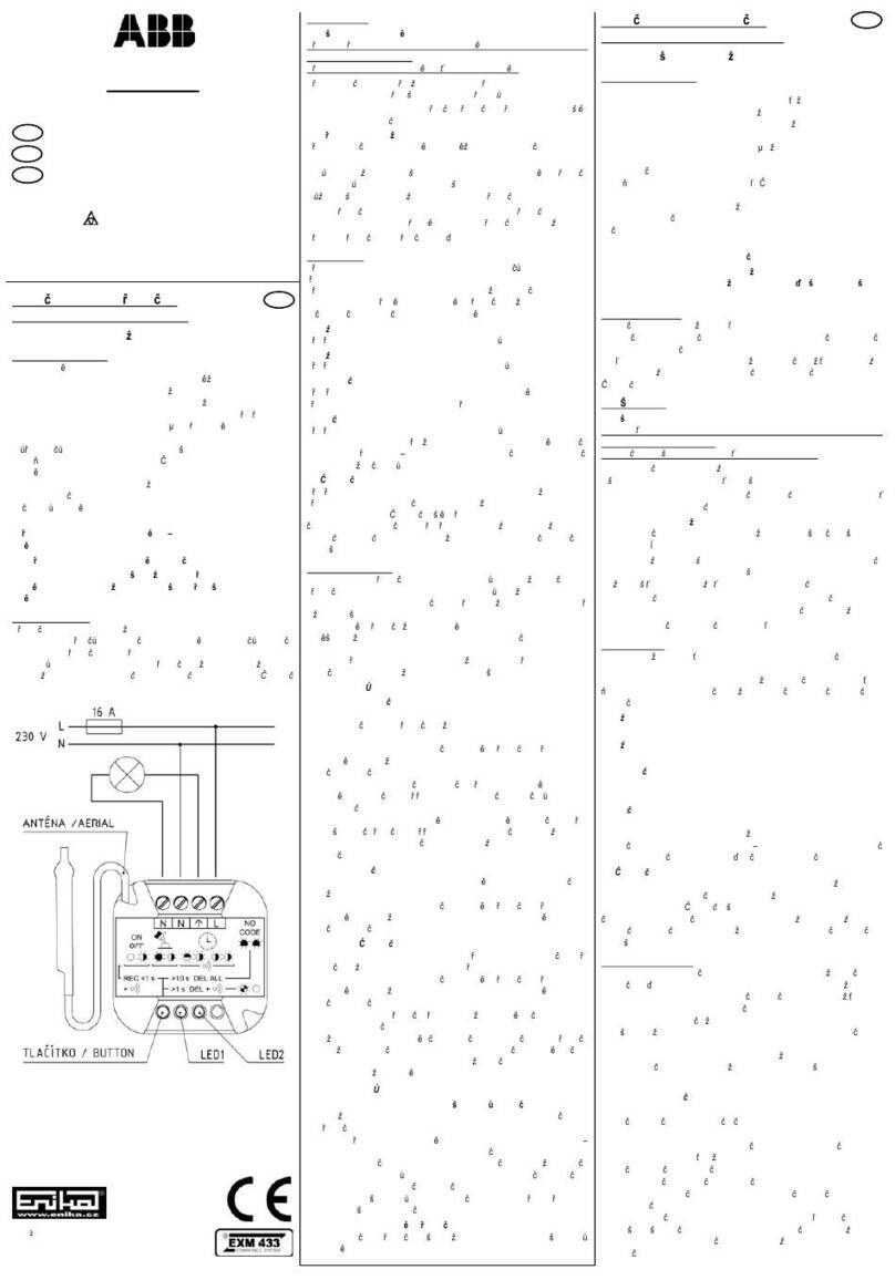
enika
enika ABB 3299-11500 quick start guide
