FM Systems RVP-412 User manual
TVP-20 / RVP-412
CCTV VIDEO-PLEXER
INSTRUCTION BOOK
IB640701
4-1-2003

TABLE OF CONTENTS
DESCRIPTION 3
MOUNTING INSTRUCTIONS 3
RVP-412 MOUNTING INSTRUCTIONS 3-4
HOW TO CABLE THE TVP-20 5
HOW TO CABLE THE RVP-20 5
POWER SUPPLY INSTALLATION 5
OPERATION 5
CARE AND MAINTENANCE 5
APPLICATIONS (WHERE TO USE THE SYSTEM) 5
APPLICATIONS (LONG DISTANCE VIDEO ON COAX) 6
RVP-412.ISB PAGE 1 OF 4

DESCRIPTION
These devices are used to transmit two CCTV Camera signals
over a single Coaxial Cable at the same time. This system can be
used to Add-On a second camera in an existing Coaxial camera
system without the need to run additional cable. It can also be
used to improve transmission of CCTV pictures over long cable
runs. The system is simple to install and convenient. It will save
you the expense of running a new cable back to the monitor point
just to add one more camera to your system. Any video cable in
your system can carry two video signals back to the monitor
location.
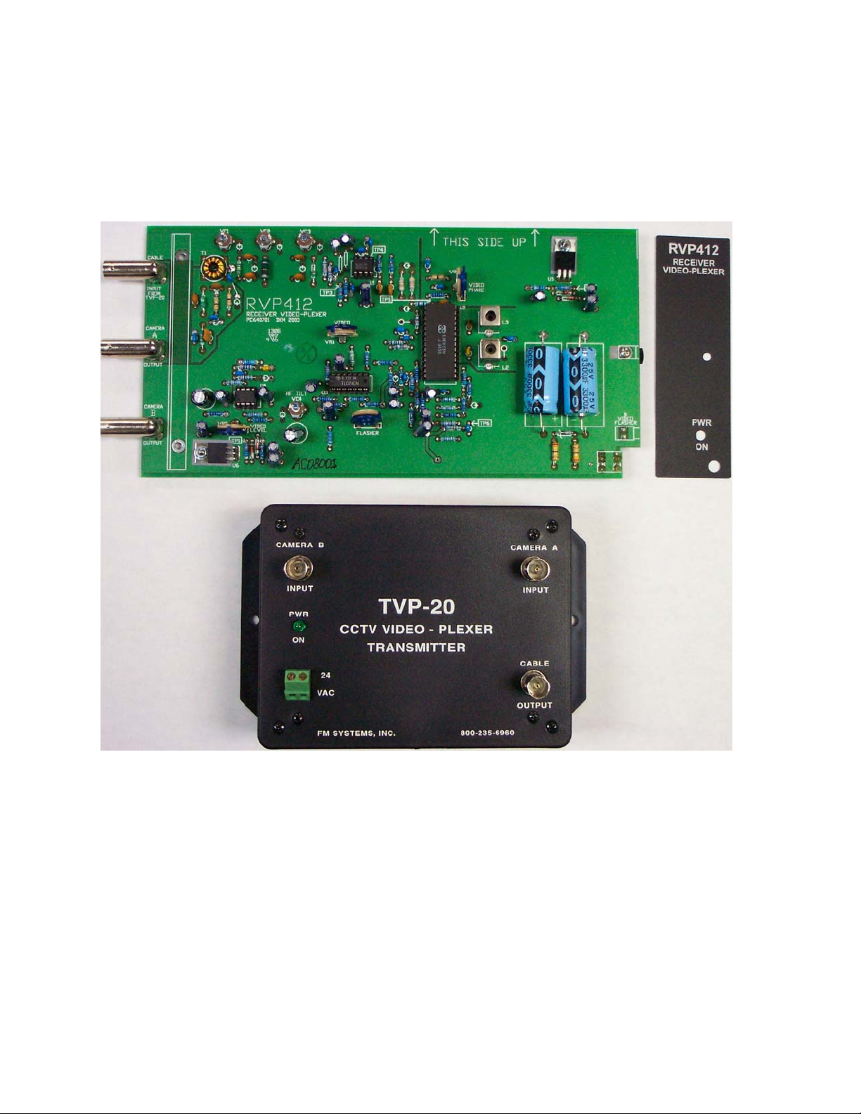
The TVP-20 TRANSMITTER VIDEO-PLEXER is the transmitter module
used to Encode and transmit the two video signals. Simply connect
the two cameras to the input connectors, connect the power supply
and use a single cable back to the monitor site.
The RVP-20 RECEIVER VIDEO-PLEXER is the receiver module used
to receive and decode the two video signals. Simply connect the
cable coming from the TVP-20 to the cable input connector, then
take camera A and B outputs to your Quad, Switcher, Monitors, etc.
Connect the power supply and you are ready to go.
The system is housed in a black ABS enclosure that has a UL
flame rating of 94-VO and is powered by any 24VAC power
transformers. The system has an LED power indicator light to help
installation.
The RVP-412 is a slide in rack mounted card that is identical
in operation to the RVP-20. The rack mounted card version mounts
into the RMS-400 mainframe and power supply.
MOUNTING INSTRUCTIONS
The rugged one piece mounting structure allows you to mount
the unit firmly in place with two screws. Select a place to mount
the unit away from harsh or wet environments indoors is
recommended. The TVP-20 should be located near the coaxial cable
you wish to use and the RVP-20 near your monitors or the place you
wish to bring the video signal to. Select a position that gives
you the best access to cable the system and reduces the labor in
installation.
RVP-412 MOUNTING INSTRUCTIONS
The RVP-412 card slides into one of the nine positions in the
RMS-400 power supply and mainframe. Select a place to mount the
RMS-400 away from harsh or wet environments indoors is mandatory.
The RVP-412 should be located near the monitor equipment or the
place you wish to bring the video signal to. Select a position
that gives you the best access to cable the system and reduces the
labor in installation.
RVP-412.ISB PAGE 2 OF 4

RVP-412 MOUNTING INSTRUCTIONS (cont.)
Select one of the un-used nine positions in the RMS-400 to be
occupied by the new RVP-412 circuit board module. Remove the blank
label in that position by peeling it off of the front panel. Peel
the label slowly to remove all of the label and adhesive. Any
remaining adhesive may be removed by rubbing the surface with your
thumb. WARNING: DO NOT USE SOLVENTS TO REMOVE THE LABEL ADHESIVE.
The solvent could damage the equipment cards or cause a fire.
Peel the backing off of the new label and apply it to the
front panel of the RMS-400 rack in the position of the new
card. Align the new label with the screw head in the hole in the
lower right hand corner of the label then align the center
thumbscrew hole with the clearance hole in the front panel. This
should cause the label to be straight and vertical. When the label
is in place press firmly to secure the label.
Then remove the thumb-screw retainer from the RVP-412, it is
located at the front of the card and is removed by rotating the
knob counter-clock-wise.
Next slide the card into the card guides at the rear of the
RMS-400. Be sure that the notch in the circuit card is facing
forward and down. Push the card all the way to the front of the
rack until it stops. DO NOT APPLY EXCESSIVE FORCE TO THE CARD.
Insert the thumb-screw that was previously removed while
rotating it in a clock-wise direction. When it begins to thread
into the card, continue until it is finger tight. CAUTION TIGHT BY
HAND ONLY, DO NOT USE TOOLS TO TIGHTEN THE THUMB-SCREW. OVER
TIGHTENING WILL DAMAGE THE CIRCUIT CARD.
CAUTION:
Most circuit board modules have several adjustments which are
carefully factory set with precision instruments for optimum
performance. Change only those which must be adjusted, some
controls when mis-adjusted produce little change under normal
operating conditions, but can seriously reduce the ability of
the unit to function correctly under other conditions which may be
encountered. Therefore, if you must adjust a control, place a
mark on it before moving it, so that it may be returned to its
original setting with reasonable accuracy.
HOW TO CABLE THE TVP-20
Connect the video cable you wish to use to the "CAMERA A INPUT"
BNC connector and connect the cable going to the RVP-20 to the
"CABLE OUTPUT" BNC connector. It is not necessary for power to be
on at this time, the video path will only be interrupted during
the cable attachment. Next connect the Second camera video output
to the "CAMERA B INPUT". BE SURE TO TERMINATE THE END OF THE VIDEO
CABLE WITH A 75 OHM TERMINATION OR PROPERLY TERMINATE INTO OTHER
EQUIPMENT.
RVP-412.ISB PAGE 3 OF 4

HOW TO CABLE THE RVP-20
Connect the video cable you are using to the "CABLE INPUT"
BNC on the TVP-20 and the "CAMERA A" BNC goes to the monitor,
recorder or other video equipment. Connect a cable from the second
camera output "CAMERA B" to your monitor, recorder or other video
equipment. BE SURE TO TERMINATE THE END OF THE VIDEO CABLE WITH A
75 OHM TERMINATION OR PROPERLY TERMINATE INTO OTHER EQUIPMENT.
POWER SUPPLY INSTALLATION
The TVP-20 and RVP-20 are powered by a 24 VAC wall mount
power transformer. Connect the 24 VAC power transformer to the
Green terminal block marked AC 24V. At this time you will see the
Green LED turn on to indicated power up. A 24VDC power source can
also be used if necessary.
OPERATION
The unit provides the ability to transmit two real time video
signals over a single coaxial cable. It uses Video-Plexer
technology to encode one video signal on top of the other. One
transmitter and one receiver is required to complete the system.
CARE AND MAINTENANCE
There is no routine maintenance or calibration required with
this equipment. There are no field adjustable controls inside the
box. Opening the box will void your warranty.
APPLICATIONS (WHERE TO USE THE SYSTEM)
This system can be used anywhere that a video signal in coax
cable exists. Some uses are in a CCTV camera original build, or in
an add on camera installation.
APPLICATIONS (LONG DISTANCE VIDEO ON COAX)
The unique method of transmission used by this unit allows
you to extend the distance that a video signal can travel on a
coax cable. Using the "B" channel of the VIDEO-PLEXER, a video
signal from a camera can be transmitted up to 1 mile using
ordinary low cost cable line extenders. The key feature of this
transmission method is that no degradation of the video frequency
response will occur over as much as a mile of transmission
distance. Use this method when you have a long way to go to your
video monitor location to provide improved video response.
RVP-412.ISB PAGE 4 OF 4
This manual suits for next models
1
Table of contents
Other FM Systems Transmitter manuals

Popular Transmitter manuals by other brands


Inovonics
Inovonics EN1212 installation instructions

Vaisala
Vaisala DRYCAP DMT340 SERIES user guide

Rose electronics
Rose electronics UltraLink E Series Installation and operation manual

Woxcon
Woxcon TPUH406TH-US user manual

Siemens
Siemens Sitrans LR250 instruction manual

Nautel
Nautel XR3 installation manual