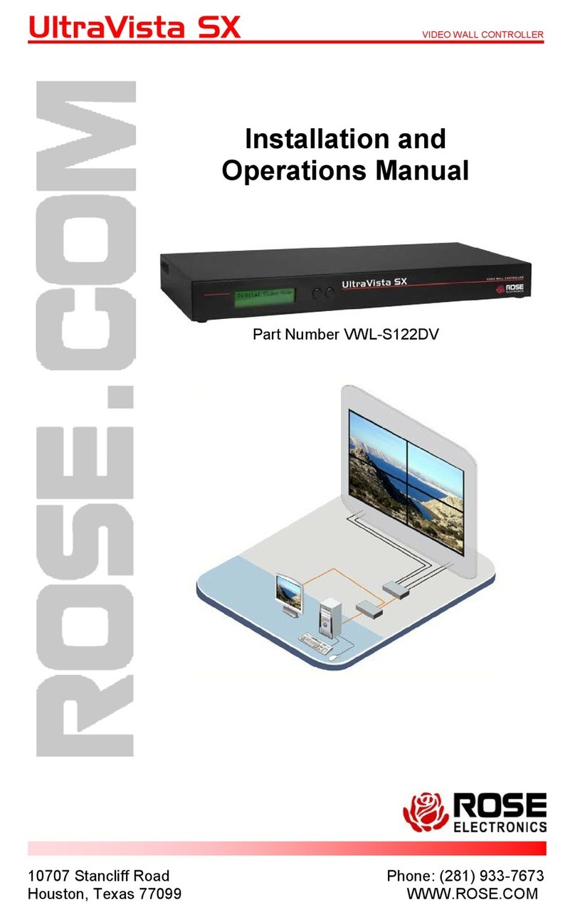
Rose electronics UltraLink E Series User manual

Ult
raLink E-Series
KVM IP System
Installation
and
Operation Manual
10707 Stancliff Road
Houston, Texas 77099
Phone: (281) 933-7673
tech-
support@rose.com

LIMITED WARRANTY
Copyright Rose Electronics 2020. All rights reserved.
No part of this manual may be reproduced, stored in a retrieval system, or transcribed in any form or any means, electronic or mechanical, including
photocopying and recording, without the prior written permission of Rose Electronics.
manual-ultralink-e-series-2020-12-30.docx
Rose Electronics®warrants the UltraLink E-Series KVM IP System to be in good working order for one year
from the date of purchase from Rose Electronics or an authorized dealer. Should this product fail to be in
good working order at any time during this one-year warranty period, Rose Electronics will, at its option,
repair or replace the Unit as set forth below. Repair parts and replacement units will be either
reconditioned or new. All replaced parts become the property of Rose Electronics. This limited warranty
does not include service to repair damage to the Unit resulting from accident, disaster, abuse, or
unauthorized modification of the Unit, including static discharge and power surges.
Limited Warranty service may be obtained by delivering the products during the one-year warranty period
to Rose Electronics or an authorized repair center providing a proof of purchase date. If the products is
delivered by mail, you agree to insure the Unit or assume the risk of loss or damage in transit, to prepay
shipping charges to the warranty service location, and to use the original shipping container or its
equivalent. You must call for a return authorization number first. Under no circumstances will a unit be
accepted without a return authorization number. Contact an authorized repair center or Rose Electronics
for further information.
ALL EXPRESS AND IMPLIED WARRANTIES FOR THIS PRODUCT INCLUDING THE WARRANTIES OF
MERCHANTABILITY AND FITNESS FOR A PARTICULAR PURPOSE, ARE LIMITED IN DURATION TO A PERIOD
OF ONE YEAR FROM THE DATE OF PURCHASE, AND NO WARRANTIES, WHETHER EXPRESS OR IMPLIED,
WILL APPLY AFTER THIS PERIOD. SOME STATES DO NOT ALLOW LIMITATIONS ON HOW LONG AN
IMPLIED WARRANTY LASTS, SO THE ABOVE LIMITATION MAY NOT APPLY TO YOU.
IF THIS PRODUCT IS NOT IN GOOD WORKING ORDER AS WARRANTIED ABOVE, YOUR SOLE REMEDY
SHALL BE REPLACEMENT OR REPAIR AS PROVIDED ABOVE. IN NO EVENT WILL ROSE ELECTRONICS BE
LIABLE TO YOU FOR ANY DAMAGES INCLUDING ANY LOST PROFITS, LOST SAVINGS OR OTHER
INCIDENTAL OR CONSEQUENTIAL DAMAGES ARISING OUT OF THE USE OF OR THE INABILITY TO USE
SUCH PRODUCT, EVEN IF ROSE ELECTRONICS OR AN AUTHORIZED DEALER HAS BEEN ADVISED OF THE
POSSIBILITY OF SUCH DAMAGES, OR FOR ANY CLAIM BY ANY OTHER PARTY.
SOME STATES DO NOT ALLOW THE EXCLUSION OR LIMITATION OF INCIDENTAL OR CONSEQUENTIAL
DAMAGES FOR CONSUMER PRODUCTS, SO THE ABOVE MAY NOT APPLY TO YOU. THIS WARRANTY GIVES
YOU SPECIFIC LEGAL RIGHTS AND YOU MAY ALSO HAVE OTHER RIGHTS WHICH MAY VARY FROM STATE
TO STATE.

TABLE OF CONTENTS
Contents
Disclaimer 1
System Introduction 1
Features 1
Package Contents 2
Control software 3
Rose UltraLink Device Manager software 3
OSD (on-screen display) 3
UltraLink E-Series Models 4
PCIe Transmitter Cards 4
Transmitter Appliances 6
Receiver Appliances 8
Description of LED Indicators 10
Reset switch for rebooting or configuration reset 13
Preparing your UltraLink hardware 14
Installing the PCIe Transmitter Card 14
Installing an SFP module 15
Removing an SFP Module 15
Connection precautions 16
Connecting your computers to the transmitter appliance 17
Connecting host USB 17
Connecting DisplayPort video 17
Connecting HDMI, DVI, or VGA video 17
Connecting audio and serial 17
Connecting local access to the transmitter appliance 18
Connecting your displays and devices to the receiver appliance 19
Connecting USB Devices 19
Connecting DisplayPort video 19
Connecting audio and serial 19
Connecting power to the UltraLink transmitters and receivers 20
PCIe Transmitter Card power 20
Transmitter and receiver power 20
Connecting network cable
—
point-to-point and networked modes 21
Setting up point-to-point mode 22
Setting up link redundancy in point-to-point mode 23
Accessing the OSD in point-to-point mode 23
OSD Sources tab in point-to-point mode 24
OSD Receiver tab in point-to-point mode 25
Setting up networked mode 28
Setting up link redundancy in networked mode 29
Installing Rose UltraLink Device Manager software 30
Accessing the UltraLink Device Manager software interface (Windows 7/10) 30
Accessing the OSD in networked mode 31
OSD Sources tab in networked mode 32

OSD Receiver tab in networked mode 33
Aggregator Mode 34
Rebooting or resetting your UltraLink devices 38
When to reboot or reset your device 38
Software reboot using the UltraLink Device Manager 38
Software reboot using the OSD (point-to-point mode only) 38
Hardware reboot or configuration reset using the reset switch 39
Changing the operation mode of your devices 39
Updating UltraLink E-Series firmware 40
Firmware update procedure – point-to-point mode 40
Firmware update procedure – networked mode 41
Troubleshooting 44
What to do if you have a problem 44
Common problems and solutions 44
Safety 46
Maintenance and Repair 48
Technical Support 48
Appendix A – Specifications 49
Appendix B – Part Numbers 51
Appendix C – Firewall requirements 51
UltraLink E-Series Device Manager software 51
UltraLink E-Series firmware updater 51
UltraLink E-Series network firewall requirements 52
UltraLink E-Series accessing your Windows firewall settings 52
Adding rules to your Windows Firewall settings 53
Appendix D – Rack-mounting options 54
Mounting guidelines 54
Appendix E – Configuring your audio settings 55
Receiver output 55
Receiver input 56
Receiver audio destination 56
Appendix F – Firmware release notes version 3.01.00 57
Notes and limitations 57
Known issues 58
Aggregator mode compatibility 58
Appendix G – Declaration of Conformity 59

Figures
Figure 1. UltraLink Device Manager main screen 3
Figure 2. PCIe transmitter cards 4
Figure 3. Transmitter appliance - front and rear view 6
Figure 4. Receiver appliance - front and rear view 8
Figure 5. PCIe Transmitter Card – Status LED 10
Figure 6. PCIe Transmitter Card – Network LED 10
Figure 7. Transmitter and Receiver Appliance – Power and status LEDs 11
Figure 8. Transmitter and Receiver Appliance – LAN 1 network Indicators 12
Figure 9. Transmitter and Receiver Appliance – LAN 2 network Indicator 12
Figure 10. PCIe card – reset switch 13
Figure 11. Transmitter and Receiver Appliance – reset switch 13
Figure 12. Installing an SFP Module 15
Figure 13. Removing an SFP module 15
Figure 14. Transmitter and receiver connections for 4K60 resolution 16
Figure 15. Removing DisplayPort cables with locking safety connectors 16
Figure 16. DisplayPort video cables from computer to transmitter 17
Figure 17. Audio and serial cables from computer to transmitter 17
Figure 18. Local connections on transmitter 18
Figure 19. DisplayPort video cables from transmitter appliance to display 19
Figure 20. Audio and serial connections from receiver appliance to audio device 19
Figure 21. PCIe 2-port transmitter card with fiber 20
Figure 22. UltraLink E-series units in point-to-point mode 21
Figure 23. UltraLink E-series units in networked mode 21
Figure 24. Screen showing initial point-to-point mode not enabled 22
Figure 25. Screen showing select operation mode for enabling point-to-point mode 22
Figure 26. OSD Sources tab in point-to-point mode 24
Figure 27. OSD Receiver tab in point-to-point mode 25
Figure 28. Redundant Network Link Connections 29
Figure 29. OSD Sources tab in networked mode 32
Figure 30. OSD Receiver tab in networked mode 33
Figure 31. Aggregator mode 34
Figure 32. Creating an Aggregate Mode Layout 36
Figure 33. OSD Dynamic Sources Tab 37
Figure 34. UltraLink Device Manager software reboot interface 38
Figure 35. OSD software reboot interface 38
Figure 36. Reset switch location 39
Figure 37. Update firmware – Devices found after automatic search and authentication 41
Figure 38. Update firmware – Authentication dialog for devices with a password 42
Figure 39. Update firmware – Authentication dialog for devices without a password 43
Figure 40. Update firmware – Update in progress and update complete message 43

Tables
Table 1. Description of transmitter card connections 5
Table 2. Description of transmitter appliance connections 7
Table 3. Description of receiver appliance connections 9
Table 4. PCIe Transmitter Card: Indicator LEDs 10
Table 5. PCIe Transmitter Card Network Indicator 10
Table 6. Transmitter and Receiver Appliance – Power and status LEDs 11
Table 7. Transmitter and Receiver Appliance – LAN 1 network LEDs 12
Table 8. Transmitter and Receiver Appliance – LAN 2 network LED 12
Table 9. PCIe Transmitter Card installation 14
Table 10. Basic OSD functions in point-to-point mode 23
Table 11. Receiver: audio settings 25
Table 12. Receiver: monitor settings 26
Table 13. Receiver: RS232 settings 26
Table 14. Receiver: more options 26
Table 15. Basic OSD functions in networked mode 31
Table 16. Reboot or reset the UltraLink 38


INTRODUCTION
UltraLink E-Series Manual 1
Disclaimer
While every precaution has been taken in the preparation of this manual, the manufacturer assumes no
responsibility for errors or omissions. Neither does the manufacturer assume any liability for damages
resulting from the use of the information contained herein. The manufacturer reserves the right to change
the specifications, functions, circuitry of the product, and manual content at any time without notice. The
manufacturer cannot accept liability for damages due to misuse of the product or other circumstances
outside the manufacturer’s control. The manufacturer will not be responsible for any loss, damage, or
injury arising directly or indirectly from the use of this product. (See limited warranty.)
System Introduction
Thank you for choosing UltraLink E-Series KVM IP System. These products are the result of Rose
Electronics’ continuing commitment to providing state-of-the-art KVM extension solutions for today’s
demanding workplace. The UltraLink E-Series product uses a highly optimized, ultra-low bitrate encoding
platform to transmit 4Kp60 4:4:4 DisplayPort desktops (3840x2160@60Hz) over CATx cables at distances
up to 325 feet (100m). Fiber interconnects increase the extension distance, from 1804 feet (multi-mode
cable) to 6.20 miles (single-mode cable).
The UltraLink E-Series KVM IP System can be deployed in point-to-point mode or networked mode,
enabling remote access to a single computer or to multiple computers. In addition to DisplayPort video,
these devices extend the signals of multiple types of computer peripherals: USB keyboard and mouse,
USB 2.0 devices, analog audio devices, and RS-232 devices). The UltraLink E-Series 4-port models
support up to four video streams and monitors. The 2-port models support up to two streams and
monitors.
If an integrated solution is preferred at the computer rack, the PCIe card versions of the transmitter
model mount inside the computers. The PCIe card versions also support two or four video displays.
Features
■Available as compact 2-port or 4-port transmitter and receiver models, or as PCIe transmitter cards for
installation in a PC case
■USB device support includes keyboard and mouse as well as flash drives and a range of USB 2.0
devices
■Low network bandwidth simplifies and lowers the cost of network installation
■Video is encrypted for increased security
■Seamless switching function presents new video instantly
■OSD provides user login and switching capability with a thumbnail preview function
■Based on user login, access to computers or type of USB device can be restricted
■USB keyboard and mouse can be programmed for shared or single user access only
■Programmable hot keys sequences simplify switching
■Integrates with existing networking equipment and standard gigabit Ethernet infrastructure
■Appliance models offer redundant network support
■Compatible with Microsoft® Active Directory Services for user authentication, and with SNMP for
remote monitoring
■Rack mounting available
■DisplayPort active converters for HDMI or DVI input or output are available

UltraLink E-Series Manual 2
Package Contents
The package contents consist of the following:
2-Port and 4-port PCIe transmitter card
■1 x PCIe transmitter card
■1 x USB cable (A to mini B)
■1 x RJ45 transceiver
2-port and 4-port transmitter models
■1 x transmitter appliance
■1 x USB-AB cable
■1 x external PSU
■1 x power cord
2-port and 4-port receiver models
■1 x receiver appliance
■1 x external PSU
■1 x power cord
SFP modules may be already inserted or supplied separately depending upon order details.
Additional cables are usually ordered separately. If the package contents are not correct, contact Rose
Electronics or your reseller so the problem can be quickly resolved.
Other items may be required to complete your installation. These items can include any of the following.
Contact Rose Electronics if any of the following items are required.
Rack mount kit
CAT5e, CAT6, or CAT7 cable
LC terminated multi-mode fiber optic cable (62.5/125 μm (OM1), 50/125 μm (OM2, OM3, or OM4))
LC terminated single-mode fiber optic cable (9/125 μm (OS1 or OS2))
Shielded DisplayPort 1.1 or 1.2 cable
Mini DisplayPort to DisplayPort adapter
Analog audio cable

UltraLink E-Series Manual 3
Control software
Rose UltraLink Device Manager software
In networked mode (see Setting up networked mode), you can remotely manage, monitor, and configure
your networked devices with Rose UltraLink E-series Device Manager software, This runs under Windows
on a separate PC attached to the LAN (see Installing Rose UltraLink Device Manager software). This
software is not required in order to operate the product, but may be required for advanced configuration
and can also be used to do switching. This is not used when connected in point-to-point mode (see Setting
up point-to-point mode).
Figure 1. UltraLink Device Manager main screen
OSD (on-screen display)
The OSD on the receiver appliance is accessed from the keyboard. The OSD is invoked with a
programmable hot-key whose default is ScrollLock, It is available for both networked and point-to-point
modes. Use it for configuration and in networked mode to preview video streams and perform switching to
different transmitters.

HARDWARE DESCRIPTION
UltraLink E-Series Manual 4
UltraLink E-Series Models
The UltraLink E-Series is available in the models described below.
PCIe Transmitter Cards
2-port Transmitter Card
4-port Transmitter Card
Figure 2. PCIe transmitter cards
Diagnostic
Power LEDs
Reset switch
Status LED
Network
LAN LED
SFP
Host connections
USB Video in ports 1–2
2.0 DP 1.1
Diagnostic
Power LEDs
Reset switch
Status LED
Host connections
USB Video in ports 1–4
2.0 Port 4 DP1.2, others DP1.1
Network
LAN LED
SFP

UltraLink E-Series Manual 5
Host connections
2-Port model
Video in ports 1–2
Connect your host computer or video sources here using DisplayPort male to male cables
(not supplied). Standard DisplayPort 1.1 resolutions are supported. Maximum resolution
depends upon number of ports used. For more information, see DisplayPort video
resolutions.
4-Port model
Video in ports 1–4
Connect your host computer or video sources here using DisplayPort (mini) male to male
cables (not supplied). Standard DisplayPort 1.1 resolutions are supported. In addition port
4 supports DisplayPort 1.2 resolutions when this is the only port used. Maximum resolution
depends upon number of ports used. For more information, see DisplayPort video
resolutions and Connecting DisplayPort video.
USB 2.0 This USB mini B female receptacle connects to the host computer using the included USB A
to mini-B cable.
Network
Network LED
LED Color Status
Off No connection
Green (fast blink) Network cable detected, transmitting at 1Gbps
Amber (fast blink) Network cable detected; current transmission speed not supported
Red (fast blink) Network cable detected; transmission error occurred
LAN SFP
Fiber or Copper
This SFP cage supports a standard SFP plug-in module, either fiber or copper. The module
can then be connected with fiber Dual LC cables or a cat5e or better Ethernet cable to
either a receiver unit in point-to-point mode or to a 1Gb Ethernet switch in networked
mode. For more information, see Installing the SFP module. Distances are governed by the
choice of module that has been installed.
Diagnostic
Power LEDs When PCIE card is powered on, these LEDs should all turn green right away.
Reset switch
Hardware reboot Quickly press the reset button (1 second) to reboot the device.
Configuration reset Press and hold the reset button for about 5 seconds (until the LED
turns fast blinking green) to reboot the device and reset to the
default settings.
Status LED
LED Color
Green (standby)
Green (solid)
Green (fast blink)
Amber (solid)
Amber (slow blink)
Amber (fast blink)
Red (solid)
Red (slow blink)
Red (fast blink)
Status
Device is turned off, but still powered
Device is active
Configuration reset in process
Card is in maintenance mode
Card is restarting in maintenance mode
Device is updating firmware
No source detected
No network detected
Device has detected a fatal error. Try rebooting the card. If the LED
is still rapidly blinking red after rebooting the card, contact Rose
Electronics for technical support. For more information on
rebooting, see Rebooting or resetting your UltraLink devices.
Table 1. Description of transmitter card connections

UltraLink E-Series Manual 6
Transmitter Appliances
2-port Transmitter Appliance
4-port Transmitter Appliance
Figure 3. Transmitter appliance - front and rear view
Host connections Line in Serial
Video in ports 1 – 2
DP1.1 Line out USB 2.0
Local connections
Video loop out USB 2.0 devices
Power and Status
Host connections Line in Serial
Video in ports 1 – 4
Port 4 DP1.2, others DP1.1 Line out USB 2.0
Power and Status
Network and Power in
LAN2 LAN1 Power in
Network and Power in
LAN2 LAN1 Power in
Local connections
Video loop out USB 2.0 devices

UltraLink E-Series Manual 7
Power and Status
Power LED Illuminates with green, amber, or red either solid or flashing to indicate various conditions of
booting and maintenance. See Transmitter and Receiver Appliance – Power and Status LEDs.
Status LED
Illuminates with green, amber, or red either solid or flashing to indicate various conditions of
peripheral conditions or errors. See Transmitter and Receiver Appliance – Power and Status
LEDs.
Power switch
This momentary switch is used to power the unit on and off. By the OSD you can disable the
power switch or set the unit to come up in a specified on/off state when power is applied to
the unit by programming the power policy state. See Additional OSD options.
Reset switch
Recessed switch is accessed with tip of paper clip for reboot or reset to factory default.
Hardware reboot Press the reset button (1 second) to reboot the device.
Configuration reset Press and hold the reset button for about 5 seconds (until the LED
turns fast blinking green) to reboot and reset to default.
Local connections
FEATURE NOT ENABLED AS OF FIRMWARE VERSION 3.01
Video loop out
Optionally connect a DisplayPort monitor to this connector using a DisplayPort male to male
cable (not supplied). This port is electrically split from the DisplayPort video input 1 from the
host for convenience purposes of viewing the host at its location.
USB 2.0 Devices Connect a keyboard and mouse to these ports to allow interaction with the host at its location.
This is typically used along with a display connected to the Video loop out mentioned above.
Host connections
2-Port model
Video in ports 1–2
Connect your host computer or video sources here using DisplayPort male to male cables (not
supplied). Standard DisplayPort 1.1 resolutions are supported. Maximum resolution depends
upon number of ports used. For more information, see DisplayPort video resolutions and
Connecting DisplayPort video.
4-Port model
Video in ports 1–4
Connect your host computer or video sources here using DisplayPort male to male cables (not
supplied). Standard DisplayPort 1.1 resolutions are supported. In addition port 4 supports
DisplayPort 1.2 resolutions when this is the only port used. Maximum resolution depends upon
number of ports used. For more information, For more information, see DisplayPort video
resolutions and Connecting DisplayPort video.
Line In (audio)
Connect the line out connector (usually lime green on PC) of your host computer here using a
3.5mm male to male audio cable (not supplied). Audio is also carried on the video signals, so
this connection is optional or can be used with a separate audio source.
Line Out (audio)
Connect the line in connector (usually light blue on PC) of your host computer here using a
3.5mm male to male audio cable (not supplied). This connection must be used if a microphone
will be used at the remote side or with an additional audio output.
Serial (RS232)
This is a general purpose RS232 port that can route signals from unit to unit. There is support
for virtual serial ports where data can be sent from the network. If your RS232 device has a
DB25 connector, use a DB9 to DB25 adapter to connect your device to this connector.
USB 2.0 This USB B female receptacle connects to the host computer using the included USB AB cable.
Network and Power in
LAN 1 Copper
with dual LED
Connect this RJ45 connector using a standard copper Ethernet cable to either a receiver
appliance in point-to-point mode or to a 1Gb Ethernet switch in networked mode. Use CAT5e
or better for connection distance of up to 100m.
LAN 2 Fiber or
Copper SFP
with LED
This SFP cage supports a standard SFP plug-in module, either fiber or copper. The module can
then be connected with fiber Dual LC cables or a cat5e or better Ethernet cable to either a
receiver appliance in point-to-point mode or to a 1Gb Ethernet switch in networked mode. For
more information, see Installing an SFP module. Distances are governed by the choice of SFP
module that has been installed. The two ports LAN1 and LAN2 can either operate as one or the
other or be paired in a redundant fashion.
Power in This is the incoming power for the unit. Connect the 12V DC power supply included with your
product to this connector. Maximum power requirement for the product is 5 Amps at 12V.
Table 2. Description of transmitter appliance connections

UltraLink E-Series Manual 8
Receiver Appliances
2-port Receiver Appliance
4-port Receiver Appliance
Figure 4. Receiver appliance - front and rear view
Remote connections Video and Serial
Video out ports 1 – 2 Serial
DP1.1
Network and Power in
LAN2 LAN1 Power in
Network and Power in
LAN2 LAN1 Power in
Remote connections Video and Serial
Video out ports 1 – 4 Serial
Port 4 DP1.2, others DP1.1
Power and Status
Remote connections USB and Audio Headphone Line in
USB 2.0 Devices x6 Microphone Line out
Remote connections USB and Audio Headphone Line in
USB 2.0 Devices x4 Microphone Line out
Power and Status

UltraLink E-Series Manual 9
Power and Status
Power LED Illuminates with green, amber, or red either solid or flashing to indicate various conditions of
booting and maintenance. See Transmitter and Receiver Appliance – Power and Status LEDs.
Status LED
Illuminates with green, amber, or red either solid or flashing to indicate various conditions of
peripheral conditions or errors. See Transmitter and Receiver Appliance – Power and Status
LEDs.
Power switch
This momentary switch is used to power the unit on and off. By the OSD you can disable the
power switch or set the unit to come up in a specified on/off state when power is applied to
the unit by programming the power policy state. See Additional OSD options.
Reset switch
Recessed switch is accessed with tip of paper clip for reboot or reset to factory default.
Hardware reboot Press the reset button (1 second) to reboot the device.
Configuration reset Press and hold the reset button for about 5 seconds (until the LED
turns fast blinking green) to reboot and reset to default.
Remote connections USB and Audio
USB 2.0 Devices Connect your standard USB devices such as keyboard and mouse directly into the recevier.
You can also plug in storage device such as flash drive or peripherals such as printers.
Headphone
Connect a standard headphone here using its standard 3.5mm audio jack. If headphone does
not have 3.5mm, use the appropriate adapter to convert it. This can be separate or
combined as a headset with headphone and microphone. Plugging this in will disconnect any
speakers present in the display monitor.
Microphone
Connect a standard microphone here using its standard 3.5mm audio jack. If microphone
does not have 3.5mm, use the appropriate adapter to convert it. This can be separate or
combined as a headset with headphone and microphone.
Line In (audio) The receiver accepts an audio source on the line in jack, routed to the line out jack at the
transmitter. Connect an audio source with a 3.5mm male to male audio cable (not supplied).
Line Out (audio)
The receiver outputs an audio signal on the line out jack. The source can be from the line in
jack at the transmitter or the audio signal in the video source. Connect your audio output
such as speakers or amplifier using a 3.5mm male to male audio cable (not supplied).
Remote connections Video and Serial
2-Port model
Video out ports 1–2
Connect your displays here using DisplayPort male to male cables (not supplied). Standard
DisplayPort 1.1 resolutions are supported. For more information, see DisplayPort video
resolutions and Connecting DisplayPort video.
4-Port model
Video out ports 1–4
Connect your displays here using DisplayPort male to male cables (not supplied). Standard
DisplayPort 1.1 resolutions are supported. In addition port 4 supports DisplayPort 1.2
resolutions when this is the only port used. For more information, see DisplayPort video
resolutions and Connecting DisplayPort video.
Serial (RS232)
This is a general purpose RS232 port that can route signals from unit to unit. There is
support for virtual serial ports where data can be sent from the network. If your RS232
device has a DB25 connector, use a DB9 to DB25 adapter to connect your device to this
connector.
Network and Power in
LAN 1 Copper
with dual LED
Connect this RJ45 connector using a standard copper Ethernet cable to either a receiver
appliance in point-to-point mode or to a 1Gb Ethernet switch in networked mode. Use CAT5e
or better for connection distance of up to 100m.
LAN 2 Fiber or
Copper SFP
with LED
This SFP cage supports a standard SFP plug-in module, either fiber or copper. The module
can then be connected with fiber Dual LC cables or a cat5e or better Ethernet cable to either
a receiver appliance in point-to-point mode or to a 1Gb Ethernet switch in networked mode.
For more information, see Installing an SFP module. Distances are governed by the choice of
SFP module that has been installed. The two ports LAN1 and LAN2 can either operate as one
or the other or be paired in a redundant fashion.
Power in This is the incoming power for the unit. Connect the 12V DC power supply included with your
product to this connector. Maximum power requirement for the product is 5 Amps at 12V.
Table 3. Description of receiver appliance connections

UltraLink E-Series Manual 10
Description of LED Indicators
The LED Indicators on each device provide information on the power and status of the device and help in
troubleshooting the product.
PCIe Transmitter Card Status LED
Figure 5. PCIe Transmitter Card – Status LED
LED Color Status
Green (standby) Device is turned off, but still powered
Green (solid) Device is active
Green (fast blink) Configuration reset in process
Amber (solid) Card is in maintenance mode
Amber (slow blink) Card is restarting in maintenance mode
Amber (fast blink) Device is updating firmware
Red (solid) No source detected
Red (slow blink) No network detected
Red (fast blink)
Device has detected a fatal error. Try rebooting the card. If the LED is still rapidly
blinking red after rebooting the card, contact Rose Electronics for technical support.
For more information on rebooting see Rebooting or resetting your UltraLink devices.
Table 4. PCIe Transmitter Card: Indicator LEDs
PCIe Transmitter Card: Network LED
Figure 6. PCIe Transmitter Card – Network LED
LED Color Network
Off No power
Green (fast blink) Network cable detected, transmitting at 1Gbps
Amber (fast blink) Network cable detected; current transmission speed not supported
Red (fast blink) Network cable detected; transmission error occurred
Table 5. PCIe Transmitter Card Network Indicator

UltraLink E-Series Manual 11
Transmitter and Receiver Appliance – Power and Status LEDs
Figure 7. Transmitter and Receiver Appliance – Power and status LEDs
LED color Power LED Status LED
Green (solid) Device is active Software is ready
Green (slow blink) Device is restarting ---
Green (fast blink) Configuration reset in process ---
Amber (solid) Device is in maintenance mode Device is restarting
Amber (slow blink) Device is restarting and is in maintenance mode Firmware mismatch detected
Amber (fast blink) Device is updating the firmware Transmitter – No USB host connected
Receiver – No keyboard detected
Red (solid) --- Transmitter – no video detected
Receiver – No monitor detected
Red (slow blink) ---
No network connected or link
redundancy network cable connection is
invalid,
Red (fast blink) Error detecting the driver Fatal error occurred
Off
No power. Make sure your device is properly
installed. Also, make sure your system isn’t in
power saving mode.
-
Table 6. Transmitter and Receiver Appliance – Power and status LEDs

UltraLink E-Series Manual 12
Transmitter and Receiver Appliance – LAN1 Network LED
Figure 8. Transmitter and Receiver Appliance – LAN 1 network Indicators
LED Color LAN 1 (Left LED) LAN 2 (Right LED)
Off No activity detected Transmitting at 1Gbps
Green (solid) --- ---
Green (fast blink) Network activity detected ---
Amber (solid) --- Transmitting at 100Mbps
Table 7. Transmitter and Receiver Appliance – LAN 1 network LEDs
Transmitter and Receiver Appliance – LAN2 Network LED
Figure 9. Transmitter and Receiver Appliance – LAN 2 network Indicator
LED Color LAN 2
Off No power
Green (solid) Network activity detected
Green (fast blink) Data transfer in process
Amber (solid) No transceiver detected
Red (solid) Error establishing communication. Verify all network connections, then
reboot the devices (see Rebooting or resetting your UltraLink devices).
Table 8. Transmitter and Receiver Appliance – LAN 2 network LED

UltraLink E-Series Manual 13
Reset switch for rebooting or configuration reset
Warning:A configuration reset restores the default settings of the UltraLink E-Series device. This resets
all of the device settings, including the IP configuration and password.
Warning:Point-to-point mode – Performing a configuration reset on a Receiver also resets the
configuration of the connected Transmitter.
PCIe Transmitter Card – Reset switch
For the PCIE transmitter card, since this switch is not accessible when the PC has been closed, it is
recommended that you understand its significance in programming point-to-point mode. If you intend for
the transmitter to operate in networked mode, then do not program the product for point-to-point. Once
point-to-point mode is programmed the only way to return it to networked mode is by using this switch.
Hardware reboot – Press the Reset button for one second (the front panel LED turns slow blinking
green) to reboot the device.
Configuration reset – Press and hold the Reset button for about 5 seconds (until the front panel LED
turns fast blinking green) to reboot the device and restore default settings.
Figure 10. PCIe card – reset switch
Transmitter and Receiver Appliance – Reset switch
Hardware reboot – Press the recessed Reset button with the tip of a paper clip for one second (the
power LED turns slow blinking green) to reboot the device.
Configuration reset – Press and hold the recessed Reset button with the tip of a paper clip for about 5
seconds (until the power LED turns fast blinking green) to reboot the device and restore default settings.
Figure 11. Transmitter and Receiver Appliance – reset switch
This manual suits for next models
6
Table of contents
Other Rose electronics Transmitter manuals
Popular Transmitter manuals by other brands

Sundrax
Sundrax RadioGate Solid RGS-X-DB-AC user manual

Broadley Technologies
Broadley Technologies 14 instruction manual

Omnitronic
Omnitronic UHF-400 BP user manual

Omnitronic
Omnitronic TM-200A user manual

GESTRA
GESTRA TRV 5-40 installation instructions

NIVELCO
NIVELCO EasyTREK SP-300 Installation and programming manual