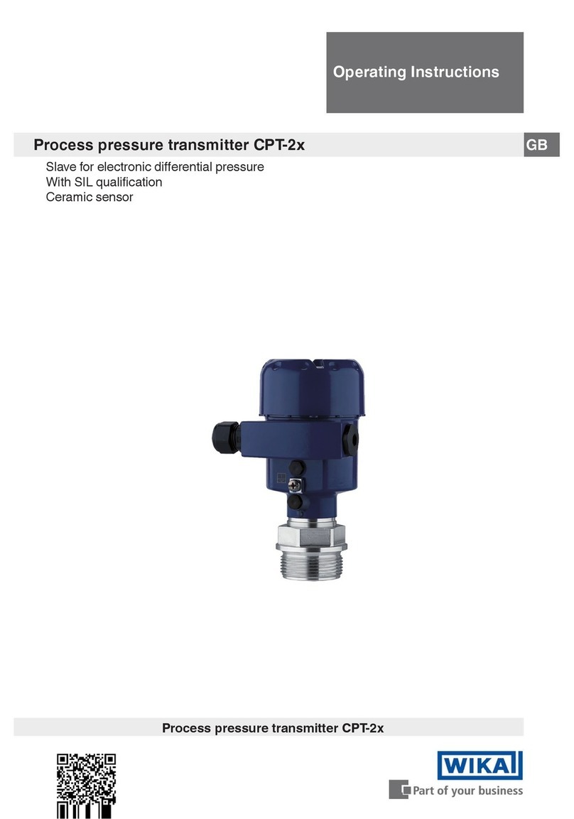
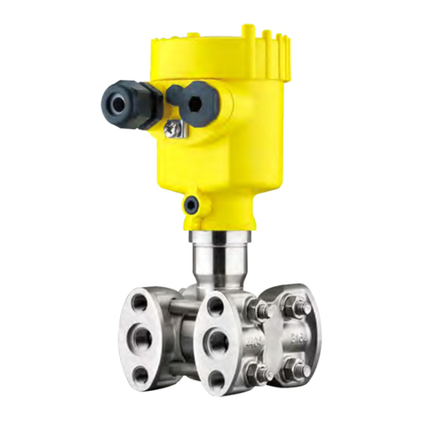
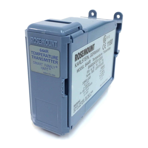
WIKA UPT-20 User manual

Operating instructions
Betriebsanleitung
GB
D
Prozesstransmitter, Typ UPT-2x
Process transmitter, model UPT-20
Process transmitter, model UPT-2x

2
14068347.01 06/2014 GB/D
WIKA operating instructions process transmitter, model UPT-2x
GB
D
© 2014 WIKA Alexander Wiegand SE & Co. KG
All rights reserved. / Alle Rechte vorbehalten.
WIKA®is a registered trademark in various countries.
WIKA®ist eine geschützte Marke in verschiedenen Ländern.
Prior to starting any work, read the operating instructions!
Keep for later use!
Vor Beginn aller Arbeiten Betriebsanleitung lesen!
Zum späteren Gebrauch aufbewahren!
Operating instructions model UPT-2x Page 3 - 62
Betriebsanleitung Typ UPT-2x Seite 63 - 122

3
WIKA operating instructions process transmitter, model UPT-2x
14068347.01 06/2014 GB/D
GB
Contents
Contents
1. General information 8
2. Safety 9
3. Specications 12
4. Design and function 20
5. Transport, packaging and storage 22
6. Commissioning, operation 23
7. Display and operating unit, model DI-PT-U 27
7.1 Design and description 27
7.2 Accessing/exiting the operating menu 27
7.3 Installation/Removal 28
7.4 Setting the main display 29
7.5 Setting the additional display 30
8. Congurationwithoutdisplayandoperatingunit 31
8.1 Performing a mounting correction (oset) 31
8.2 Conguring over HARTinterface 32
9. Congurationviadisplayandoperatingunit 33
9.1 Conguring the measuring task 33
9.1.1 Conguring pressure measurement 33
9.1.2 Conguring level measurement 34
9.2 Setting the units 35
9.2.1 Setting the pressure unit 35
9.2.2 Set length unit (for level measurement) 35
9.2.3 Setting the density unit 36

4WIKA operating instructions process transmitter, model UPT-2x
14068347.01 06/2014 GB/D
GB
Contents
9.2.4 Setting the temperature unit 36
9.3 Scaling the measuring range 37
9.3.1 Performing a wet adjustment 37
9.3.2 Performing a dry adjustment 38
9.4 Setting the mode 39
9.5 Mounting correction (oset) 40
9.5.1 Performing a wet adjustment 40
9.5.2 Performing a dry adjustment 40
9.6 Setting the damping 41
9.7 Write protection 42
9.7.1 Activating/deactivating the write protection 42
9.7.2 Changing PIN 42
10. Diagnostic functions 43
10.1 Simulations 43
10.1.1 Performing a pressure simulation 43
10.1.2 Performing a current simulation 43
10.2 Indicating/ressetting drag pointer 44
10.2.1 Drag pointer Pmin / Pmax 44
10.2.2 Drag pointer PVmin / PVmax 45
10.2.3 Drag pointer Tmin / Tmax 45
10.3 Indicating/resetting operating time 45
11. Detail setup 46
11.1 Setting the language 46
11.2 Marking the measuring point (TAG) 46
11.2.1 Setting the TAG short 46

5
WIKA operating instructions process transmitter, model UPT-2x
14068347.01 06/2014 GB/D
GB
Contents
11.2.2 Setting the TAG long 46
11.3 Setting the alarm signal 47
11.4 Setting the signal limits 47
11.5 Setting the contrast of the LC display 48
11.6 Restoring factory setting 48
11.7 Setting the HARTcommunication 49
11.7.1 Setting the short address (multidrop mode) 49
11.7.2 Activating/deactivating constant current 49
12. Instrument information 50
12.1 Indicating measuring range 50
12.2 Indicating date of manufacture 50
12.3 Indicating rmware version 50
12.4 Indicating serial number 51
13. Maintenance and cleaning 51
14. Faults 52
15. Dismounting, return and disposal 53
16. Accessories 54
Appendix 2: Menu tree, basic setting 56
Appendix 3: Menu tree, display 58
Appendix 4: Menu tree, diagnostic 59
Appendix 5: Menu tree, detail setup 60
Appendix 6: Menu tree, info 62
Declartations of conformity can be found online at www.wika.com

6WIKA operating instructions process transmitter, model UPT-2x
14068347.01 06/2014 GB/D
GB
1. General information
1. General information
■
The process transmitter described in the operating instructions has been designed
and manufactured using state-of-the-art technology. All components are subject
to stringent quality and environmental criteria during production. Our management
systems are certied to ISO 9001 and ISO 14001.
■
These operating instructions contain important information on handling the instru-
ment. Working safely requires that all safety instructions and work instructions are
observed.
■
Observe the relevant local accident prevention regulations and general safety regula-
tions for the instrument's range of use.
■
The operating instructions are part of the product and must be kept in the immediate
vicinity of the instrument and readily accessible to skilled personnel at any time.
■
Skilled personnel must have carefully read and understood the operating instructions
prior to beginning any work.
■
The manufacturer's liability is void in the case of any damage caused by using the
product contrary to its intended use, non-compliance with these operating instruc-
tions, assignment of insuciently qualied skilled personnel or unauthorised modi-
cations to the instrument.
■
The general terms and conditions contained in the sales documentation shall apply.
■
Subject to technical modications.
■
Further information:
- Internet address: www.wika.de / www.wika.com
- Relevant data sheet: PE 86.05
- Application consultant: Tel.: +49 9372 132-0
Fax: +49 9372 132-406
info@wika.com
Explanation of symbols
WARNING!
... indicates a potentially dangerous situation that can result in serious injury
or death, if not avoided.

7
WIKA operating instructions process transmitter, model UPT-2x
14068347.01 06/2014 GB/D
GB
1. General information / 2. Safety
CAUTION!
... indicates a potentially dangerous situation that can result in light injuries
or damage to equipment or the environment, if not avoided.
Information
... points out useful tips, recommendations and information for ecient and
trouble-free operation.
2. Safety
WARNING!
Before installation, commissioning and operation, ensure that the appro-
priate instrument has been selected in terms of measuring range, design
and specic measuring conditions.
Non-observance can result in serious injury and/or damage to the equip-
ment.
Further important safety instructions can be found in the individual
chapters of these operating instructions.
2.1 Intended use
The process transmitter measures gauge pressure, absolute pressure and vacuum. The
physical quantity pressure is converted into an electrical signal.
The process transmitter has been designed exclusively for industrial applications in
internal and external locations. Its scope of application is dened by its technical perfor-
mance limits and its materials. Improper use is dened as any application that exceeds
the technical performance limits or is not compatible with the materials. Checking
against improper use is the responsibility of the operator.
The instrument has been designed and built solely for the intended use described here,
and may only be used accordingly.
The technical specications contained in these operating instructions must be
observed. Improper handling or operation of the instrument outside of its technical
specications requires the instrument to be taken out of service immediately and
inspected by an authorised WIKA service engineer.
The manufacturer shall not be liable for claims of any type based on operation contrary
to the intended use.

8WIKA operating instructions process transmitter, model UPT-2x
14068347.01 06/2014 GB/D
GB
2. Safety
2.2 Personnelqualication
WARNING!
Riskofinjuryshouldqualicationbeinsucient!
Improper handling can result in considerable injury and damage to equipment.
The activities described in these operating instructions may only be carried
out by skilled personnel who have the qualications described below.
Skilled personnel
Skilled personnel are understood to be personnel who, based on their technical training,
knowledge of measurement and control technology and on their experience and knowl-
edge of country-specic regulations, current standards and directives, are capable of
carrying out the work described and independently recognising potential hazards.
Special operating conditions require further appropriate knowledge, e.g. of aggressive
media, compatibility of materials.
2.3 Personalprotectiveequipment
The personal protective equipment is designed to protect the skilled personnel from
hazards that could impair their safety or health during work. When carrying out dierent
work on and with the instrument, personal protective equipment must be worn.
Followtheinstructionsdisplayedintheworkarearegardingpersonalprotective
equipment!
The requisite personal protective equipment must be provided by the operating
company.
2.4 Specialhazards
WARNING!
For hazardous media such as oxygen, acetylene, ammable or toxic gases
or liquids, and refrigeration plants, compressors, etc., in addition to all
standard regulations, the appropriate existing codes or regulations must also
be followed.
WARNING!
Residual media in the dismounted process transmitter can result in a risk to
personnel, the environment and equipment.
Take sucient precautionary measures.

9
WIKA operating instructions process transmitter, model UPT-2x
14068347.01 06/2014 GB/D
GB
2. Safety
2.5 Labelling, safety marks
Product label
Pin assignment Model code
Power supply S# Serial no.
Output signal P# Product no.
Measuring range Date of manufactureYYYY-MM
Explanation of symbols
Before mounting and commissioning the instrument, ensure you read the
operating instructions!
CE, Communauté Européenne
Instruments bearing this mark comply with the relevant European directives.
Output signal
Powersupply
Ground (GND)

10 WIKA operating instructions process transmitter, model UPT-2x
14068347.01 06/2014 GB/D
GB
3.Specications
3. Specications
3.1 Measuring range (see product label)
Gauge pressure
bar 0 ... 0.4 0 ... 1.6 0 ... 6 0 ... 16 0 ... 40
0 ... 100 0 ... 250 0 ... 600 0 ... 1,000
psi 0 ... 10 0 ... 15 0 ... 30 0 ... 100 0 ... 300
0 ... 500 0 ... 1,500 0 ... 5,000 0 ... 10,000
Absolute pressure
bar 0 ... 0.4 0 ... 1.6 0 ... 6 0 ... 16 0 ... 40
psi 0 ... 30 0 ... 100 0 ... 300 0 ... 500
Vacuum and +/- measuring ranges
bar -0.4 ... 0 -0.2 ... +0.2 -1 ... +0.6 -1 ... +5 -1 ... +15
-1 ... +40
psi -14.5 ... 0 -14.5 ... +15 -14.5 ... +100 -14.5 ... +300 -14.5 ... +600
Vacuumtightness
Vacuum resistance is provided, except for instruments for oxygen applications.
Overpressurelimit
Measuring range Overpressurelimit
≤ 16 bar/300 psi 3 times
> 16 bar/300 psi 2 times

11
WIKA operating instructions process transmitter, model UPT-2x
14068347.01 06/2014 GB/D
GB
3.Specications
3.2 Accuracy data
Accuracy at reference conditions
Including non-linearity, hysteresis, zero oset and end value deviation (corresponds to
measured error per IEC 61298-2).
Accuracy
Standard 0.15 % of span
Option 1 0.10 % of span
Option 2 0.20 % of span
Mounting correction
-20 ... +20 %
Non-repeatability
≤ 0.15 % of span
Behaviourwithturndown(withaccuracy0.15%)
Turndown = basic measuring range : scaled measuring range
■
1:1 ... 5:1 No change in accuracy
■
> 5:1 < 0.03 % x turndown
Long-term stability
≤ (0.1 % x turndown)/year
Thermalchangezeropoint/span(referencetemperature20°C)
In compensated range 10 ... 70 °C:
< 0.05 % / 10 K x turndown
Outside compensated range:
Typical < 0.1 % / 10 K x turndown
Thermalchangeofthecurrentoutput(referencetemperature20°C)
< 0.05 % / 10 K, max. 0.15 %

12 WIKA operating instructions process transmitter, model UPT-2x
14068347.01 06/2014 GB/D
GB
3.Specications
3.3 Operating conditions
The process pressure transmitter is suitable for internal and external operation.
Direct exposure to sunlight is permitted.
Humidity
≤ 93 % r. h.
Ambient temperature
Instrument with display: -20 ... +60 °C
Instrument without display: -40 ... +80 °C 1)
1) Instrument with angular connector or circular connector: -30 ... +80 °C
Storage temperature
-40 ... +80 °C
Medium temperature
Oxygen application: -20 ... +60 °C
Model UPT-20: -40 ... +85 °C
-40 ... +105 °C at max. 40 °C ambient temperature
-40 ... +120 °C at max. 30 °C ambient temperature
Model UPT-21: Depending on sealing, cooling element and ambient temperature
UPT-21 without cooling element:
85 °C at max. 80 °C ambient temperature
105 °C at max. 40 °C ambient temperature
120 °C at max. 30 °C ambient temperature
UPT-21 with cooling element:
85 °C at max. 80 °C ambient temperature
120 °C at max. 50 °C ambient temperature
150 °C at max. 40 °C ambient temperature
Sealing
Material Medium temperature
NBR -20 ... +105 °C
FKM -20 ... +105 °C
FKM -20 ... +150 °C 2)
EPDM 1) -40 ... +105 °C
EPDM 1) -40 ... +150 °C 2)
1) EPDM only with hygienic process connection
2) Process connection with cooling element

13
WIKA operating instructions process transmitter, model UPT-2x
14068347.01 06/2014 GB/D
GB
3.Specications
Vibration resistance
4 g (5 ... 100 Hz) per GL characteristic curve 2
Shockresistance
150 g (3.2 ms) per IEC 60068-2-27
Ingress protection
IP 66/67
IP 65 for versions with circular connector, angular connector or overvoltage protection
Ingress protection only applies with closed case head and closed cable glands.
3.4 Materials
Wetted parts
■
Model UPT-20, measuring range ≤ 40 bar: Stainless steel 1.4404
■
Model UPT-20, measuring range > 40 bar: Stainless steel 1.4404 and
stainless steel 2.4711
■
Model UPT-21: Stainless steel 1.4435
Sealing material
See table “medium temperature” under chapter 3.3 “Operating conditions”
Casehead
Plastic (PBT) with conductive surface per EN 60079-0:2012
Colour: night blue RAL5022
Pressure transmission medium
Model Medium
Model UPT-20 Measuring range ≤ 40 bar:
Synthetic oil, halocarbon oil
Measuring range > 40 bar:
Dry measuring cell
Model UPT-21 Synthetic oil, halocarbon oil

14 WIKA operating instructions process transmitter, model UPT-2x
14068347.01 06/2014 GB/D
GB
3.Specications
3.5 Display and operating unit (option)
Refreshrate
200 ms
Main display
4 ½-digit
Additional display
Selectable via menu, three-line scale range
Bargraphdisplay
20 segments, radial, pressure gauge simulation
Colours
Background: light grey, digits: black
Operating state
Display via symbols
3.6 Output signal (see product label)
Signal
4 ... 20 mA
4 ... 20 mA with HART®signal
LoadinΩ
(UB- UBmin) / 0.023 A
UB = applied power supply (see “Power supply”)
UBmin = minimum permissible power supply (see “Power supply”)
Damping
0 ... 99.9 s, adjustable
After the set damping time the instrument outputs 63 % of the applied pressure as
output signal.
Settling time t90
60 ms without HART®
80 ms with HART®
Refreshrate
20 ms without HART®
50 ms with HART®

15
WIKA operating instructions process transmitter, model UPT-2x
14068347.01 06/2014 GB/D
GB
3.Specications
3.7 Voltage supply
PowersupplyUB
DC 12 ... 36 V
3.8 Electrical connections
Availableconnections Ingress pro-
tection
Wire cross-section
Cable gland M20 x 1.5 and spring-loaded terminals IP 66/67 max. 2.5 mm2 (AWG 14)
Angular connector DIN 175301-803A with mating
connector IP 65 max. 1.5 mm2
Circular connector M12 x 1 (4-pin) without mating
connector IP 65 -
The stated ingress protection only applies when plugged in using mating connectors
that have the appropriate ingress protection.
3.9 Reference conditions (per IEC 61298-1)
Temperature
23 °C ± 2 °C
Powersupply
DC 23...25 V
Atmosphericpressure
860 ... 1,060 mbar (86 ... 106 kPa, 12.5 ... 15.4 psig)
Humidity
35 ... 93 % r. h.
Characteristiccurvedetermination
Terminal method per IEC 61298-2
Curvecharacteristics
Linear
Reference mounting position
Vertical, diaphragm points downward

16 WIKA operating instructions process transmitter, model UPT-2x
14068347.01 06/2014 GB/D
GB
3.Specications
3.10 CE conformity
Pressureequipmentdirective
97/23/EC
EMCdirective
2004/108/EG interference emission (group 1, class B) and immunity per
EN 61326-1:2013 (industrial application), EN 61326-2-3:2013 and per
NAMUR NE 21:2011
During interference, increased measuring deviations of up to 0.15 % can
occur.
3.11 Dimensions in mm
Process transmitter, models UPT-20 and UPT-21

17
WIKA operating instructions process transmitter, model UPT-2x
14068347.01 06/2014 GB/D
GB
3.Specications
Hygienic Hygienic
Process connections for model UPT-20
G L1
G ⅜ B 16
G ½ B 20
M20 x 1.5 20
Hexagon dimension: 12 mm
G L1
¼ NPT 13
½ NPT 19
Hexagon dimension: 12 mm
G L1 L2 D1
½ NPT, female 20 19 26.5
Hexagon dimension: 12 mm
Process connections for model UPT-21
G L1 L2 L3 D1
G ½ B 23 20.5 10 18
Hexagon dimension: 12 mm
G L1 L2 L3 D1
G 1 B 23 20.5 10 30
Hexagon dimension: 13 mm
G L1 L2 D1
G 1 ½ B 25 22 55
Hexagon dimension: 14 mm
G L1 L2 L3 D1
G 1 B 28 25 9 29.5
Hexagon dimension: 13 mm
G L1 L2 L3 L4 D1
G 1 B 28 25 9 15.5 29.5
Hexagon dimension: 13 mm

18 WIKA operating instructions process transmitter, model UPT-2x
14068347.01 06/2014 GB/D
GB
4. Design and function
4. Design and function
4.1 Design
4.2 Description
The process transmitter processes the prevailing pressure and converts it into a current
signal. This current signal can be used for the evaluation, control and monitoring of the
process.
HART(option)
The instrument version with HART can communicate with a controller (master).
Measuringrangescaling(turndown)
The start and end of the measuring range can be set within dened ranges.
Process connection, thread Push-on cap
Process connection, spanner ats Product label
Sensor housing Ground screw, outside
Ex-relevant data Electrical connection, cable gland
Case head Second bore for cable gland (delivered sealed
with blind plug)

19
WIKA operating instructions process transmitter, model UPT-2x
14068347.01 06/2014 GB/D
GB
4. Design and function
Display and operating unit (accessory)
The display and operating unit model DI-PT-U has a main and an additional display.
The main display and the additional display are able to be set in almost any way. In the
factory setting, the main display shows the pressure value of the output signal.
The process transmitter is congured via the display and operating unit.
Adaptable to mounting position
The process transmitter is tted with a case head which can be turned through 330°.
The display and operating unit can be attached in 90° steps. Thus the measured value
can be read irrespective of the mounting position.
4.3 Scopeofdelivery
■
Pre-assembled process transmitter
■
Ordered accessories
■
Operating instructions
■
Measured value protocol
Cross-check scope of delivery with delivery note.
Displaceable display and operating unit
Rotatablecasehead
330°

20 WIKA operating instructions process transmitter, model UPT-2x
14068347.01 06/2014 GB/D
GB
5. Transport, packaging and storage
5. Transport, packaging and storage
5.1 Transport
Check the process transmitter for any damage that may have been caused by transport.
Obvious damage must be reported immediately.
5.2 Packaging
Do not remove packaging until just before mounting.
Keep the packaging as it will provide optimum protection during transport (e.g. change
in installation site, return for calibration).
5.3 Storage
Permissible conditions at the place of storage:
■
Storage temperature: -40 ... +80 °C
■
Humidity: 35 ... 93 % relative humidity (no condensation)
Avoidexposuretothefollowingfactors:
■
Proximity to hot objects, when permissible storage temperature is exceeded by
radiation
■
Mechanical vibration, mechanical shock (putting it down hard), when the permissible
values are exceeded, see chapter 3 “specications”
■
Soot, vapour, dust and corrosive gases
■
Hazardous areas and ammable atmospheres where the instruments are not suitable
for installation in or mounting to equipment in explosive atmospheres.
Store the process transmitter in its original packaging in a location that fulls the condi-
tions listed above. If the original packaging is not available, then store the instrument
in a container that is similar to the original packaging, so that the instrument can't be
scratched and is protected against damage if dropped.
WARNING!
Before storing the instrument (following operation), remove any residual
media. This is of particular importance if the medium is hazardous to health,
e.g. caustic, toxic, carcinogenic, radioactive, etc.
Other manuals for UPT-20
2
Table of contents
Languages:
Other WIKA Transmitter manuals
