JR ProPo NET-M116G User manual

Classic
Old
Looking
Transmitter

1
Introduction
ᴾ
▋Greetings
ThankyouforchoosingtopurchasethisJRproduct.
Thisisahighlydevelopedproductwithoutstanding
functionalityandergonomicsthatconcentratesthe
essenceofthetechnologybuiltupbythiscompany
throughmanydecadesofexperience.Inordertomake
fulluseofthefeaturesofthisradioandtosafelyenjoy
yourRCactivities,pleasecarefullyreadthisoperation
manual.
Ourwholecompanyhopesthatyouwillenjoyusing
thisproductformanyyears.
ᴾ
▋Features
JRʼsnewlydevelopedDMSSsystemmaintainshigh
speedservoresponsewhileallowingsimultaneous
useoftelemetryfunctions.
Thehigh-speedtelemetryfunctionallows
informationfromtheaircraft(thatwaspreviously
unknowntotheuser)tobemonitoredonthe
transmitter.Inaddition,alarmswithuniquesounds
alerttheusertothesituationontheaircraftwithout
evenlookingatthescreen.
Thetelemetrysensorconnectionemploysabus
systemthatdoesnotrequirearelaybox,allowing
sensorextensionsandadditionstobeeasilycarried
out.Itisacceptabletomerelyconnectthenecessary
sensorsinparallel.
Withourautomaticsafetysystem,thereceiver
willnotoperateifthecorrectmodelhasnotbeen
selectedinthetransmitterbeforeflight.
ThetransmitterfeaturesalargeLCDdisplayand
inputkeysthatareintuitiveandeasytouse.
ATrimInputfunctioncanallocatetrimleversto
changenumericalvaluesofvariousfunctions(such
asprogrammixvalues)duringflight.
Anewfunctionsynchronizestheoperationofservos
onmultipleflightcontrolsurfacesinrealtime.This
completelyeliminatesthetimelagwithfastcontrol
inputs.
AmicroSDcardslotenablessavingaircraftmodel
dataandupdatingoftransmittersoftwaretobe
easilycarriedout,withoutconnectingthetransmitter
toaPC.
The20-aircraftmodelmemorycanbeutilizedfor
storinghelicopter,airplane,andglidermodels.
ATrainerfunctionisincorporated,whichalsoallows
trainingtobecarriedoutindividuallyforeach
channel.
Thethrottlecurves,pitchcurves,andcurvemixing
useamultiplepointadjustingmethod,andyoucan
alsoactivateanoptionalexponentialcurvefunction
thatfurthersmoothesthecurves.
Threesystemsofmulti-functionprogrammixingare
available.
ATouchSelectfunctionisincorporated,which
enablesautomaticswitchselectionforprogrammed
functions.Thisselectioniseasilycarriedout.
AʻMyListʼscreenisprovidedthatenablesdisplay
andsimplecallingupoffrequentlyusedfunctions
thattheuserhasselected.
▋Transmitterspecifications
Item Specification
PartNumber: NET-M116G
Typeofcontrol: 6channelcomputermixing
RF: 2.4GHz
Modulation: DMSS(DualModulationSpreadSpectrumSystem)
Powersource: 6.4VLithiumFerritebattery2F1400(1400mA)
*Optional7.2VLi-ionbatteryavailable(2L3200)
Neutralposition: 1.5ms
NEM-B82A
▋ACadaptorspecifications
Item specification
Partnumber:
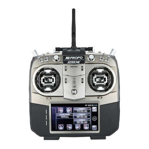
Thisisourfirstnostalgictransmitter-projectC.O.L.T.-Classic
OldLookingTransmitter.Whilethetransmitterisretroonthe
outside,witha1960'sfeel,ontheinsideitfeaturesthelatest
inJRDMSS2.4GHztechnology.
CompatiblewithXBussystem.XBuscompatibledevices
canbeadjustedthroughthetransmitter.
InputVoltage: AC100V-240V50/60Hz
DC15V30WOutputVoltage:
#04029NEC-A1530
Anewgenerationlong-lifeLi-Febatteryisusedwhich
contributestoalargereductionintransmitterweight.The
chargingcontrolcircuitisbuiltintothetransmitter.
Thisisamulti-function6-channeltransmitterthatis
capableofsupportingmanyaircraft.Ithasfunctionality
normallyonlyseeninmoreexpensivetransmitters.
Whenusingthedialtochangenumericalvalues,
simultaneouslypressingthedialandrotatingitallows
thevaluetobechangedataten-timesfasterspeed.

2
Thiscompanycannotberesponsibleforanyaccident
orfailurethatmayoccurfromanymodificationofthis
product,useofnon-genuineparts,naturaldisaster,or
nonobservanceoftheprecautionsdescribedinthis
manual.
Further,fordamagescausedbyanaccidentorfailure,
pleaseunderstandthatitems(exceptingthisproduct
andthisCompanyʼsgenuineparts)suchasairplanes,
competitorʼsproducts,etcwillnotbecoveredunder
thewarranty.
Theuseofradiowavesrequiredbythisproductis
definedintheRadioLawofJapan.
▋BasicPrecautionsforSafeUseof
the2.4GHzSystem
The2.4GHzbandisnotexclusivelyforusewithRC
airplanes.Thisfrequencybandissharedwiththe
ISM(industry,science,andmedicalcare)bandwhich
iswidelyusedforshort-distancetransmissionsuch
asmicrowaveovens,wirelessLAN,digitalcordless
phones,audiogames,cellphoneBluetooth,andVICS.
Therefore,thesteeringresponseofthe2.4GHz
systemmaybedegradedinurbanareas.
Further,asitisalsousedforhamandlocalarea
radiocommunicationsformobileidentification,
pleasepayattentiontopossibleinfluencesfrom
these.Intheeventofanyadverseradiowave
interferenceonanexistingwirelessstation,
immediatelystopemittingradiowavesandtake
interferenceavoidancemeasures.
Ataracetrackorairfield,minimizeuseofdevices
thatcanaffectthetransmitter/receiverandbesure
toconfirmsafetybeforeoperation.Also,always
followinstructionsgivenbythefacilitystaff.
Ifanaircraftisallowedtoflyoutofsightbehinda
building,apylon,trees,etc.sothattheradio-waves
areblocked,thecontrolresponsemaydrop,even
resultinginan“out-of-control”situation.Alwayslet
theaircraftflywithinanareathatcanbevisually
observed.
▋IndicationsandSymbolsRelated
toSafety
Thefollowingsymbolsusedinthismanualindicate
theprecautionsregardingpossibledangerwhichmay
occurfollowingimproperhandling.
Besuretostrictlyobservethem,astheycontain
importantsafetyinstructions.Ifincorrectoperation
methodsareused,therewillbeadangerofdeathor
seriousinjury.
Ifincorrectoperationmethodsareused,therewill
beapossibilityofdeathorseriousinjury.
DANGER
WARNING
▋HowtoHandle
Beforeusingthisproduct,ensureallpartshavebeen
provided.Connecttheswitchharnessandservostothe
receiver,andinsertbatteriestopowerthetransmitter
andreceiver.Turnonthetransmitterthenreceiverand
confirmthattheyoperatecorrectly.Iftheydonotoperate,
checkthevoltageofthebatteries.Ifarechargeable
batteryisusedforthefirsttimeafterpurchaseorisused
afterbeingleftunusedforalongperiod,besuretofully
chargeitwiththebatterychargerbeforeuse,andconfirm
thetransmitterandreceiverarecorrectlybound.
RefertothePage11"BindingProcedure"
Intheeventoffindinganymissingparts,malfunctions,
etc.,pleasecontactyourJRagentordistributorinyour
country.
Out-of-controlanddangeroussituationscanoccur.
DONOTusethisproductonrainydayssinceitmay
malfunctionifwatergetsinsidetheTransmitter
orreceiver.Ifuseisanecessity,besuretotake
waterproofingmeasures.
Injuryduetoheatgeneration,fire,orelectricshock
canoccur.Neverdisassembleormodifythisproduct.
DONOTstarttheenginewiththetransmitterthrottle
inahighspeedposition.Thisisverydangerous.
Theengineandthemotor(inthecaseofan
electrically-drivenmodel)canstartrotatingathigh
speed,causingdanger.Whenturningonthepower
switch,setthetransmitterthrottlesticktothelowest
speedposition(topreventengine/motorrotation)
andthenturnonthetransmitterpowerswitch
followedbythereceiverpowerswitch.Whenturning
offthesystem,turnoffthereceiverpowerthenthe
transmitterpowerinthisorder.
Injurycanbecaused.Whenadjustingtheengine
(motor),payattentiontothedangerspresented.DO
NOTstarttheenginewiththetransmitterthrottle
stickinahighspeedposition.Thisisverydangerous.
Failurecanbecaused.DONOTusethisradioset
incombinationwithacompetitorʼsproduct(servo,
gyro,regulator,etc).Malfunctioncanoccur.Asthe
electronicpartsmountedinthetransmitterand
receiveraresusceptibletoimpactdamage,DONOT
allowstrongimpactordropthem.
Thisindicatesactionsthatareforbidden.
Thisindicatesactionsthatmustbeimplemented.
DANGER
WARNING
Introduction
ᴾ
▋GeneralSafetyPrecautions
* Itisveryimportanttoensurethatyou
observethefollowingprecautions.
●Whenthisproductisusedoverseas,authorization
inthecountryofusewillberequired.
●Whenthisproductisusedoverseasforapurpose
otherthanasradiocontrolsystemforamodel,itmay
besubjecttotherestrictionsinaccordancewiththe
ExportTradeControlOrder.Insuchacase,anexport
permitundertheOrderisrequired.
Ifincorrectoperationmethodsareused,therewill
beapossibilityofdeathorseriousinjury.
Ifincorrectoperationmethodsareused,itcanbeexpected
thattherewillbeapossibilityofproblemsoccurring.
CAUTION

3
Out-of-controlanddangeroussituationscan
becaused.Whendegradedservomovementis
detected,immediatelystopoperatingandcheck
thebatterypowerremaining,servos,etc.
DONOTusetheproductinthefollowingplaces,
asthereisariskofanout-of-controlstateoran
accidentoccurring:
Transceiverinterferenceexists.
Operatingneartrafficconsistingofcars,
motorcyclesandmopeds(i.e.enginepowered
vehicleswithsparkignition).
Nearhigh-tensionelectriclines,buildings,banks,
hospitalsorinamountainousarea,etc.
NearFM/TVstations,oraradiotransmitting
stationforshipradios.
Nearresidencesandbuildings,andnearpeople.
Asuddenmalfunctionmayoccurandwillbe
dangerous.Evenifthereceiver,servoetc.getwet
andthenoperatenormallyafterbeingfullydried,
theservosmaylatermalfunction.Insuchcase,
DONOTcontinuetousetheproduct,andcontact
yourJRdealerordistributorinyourcountryfor
inspectionregardlessofnormaloperation.
Priortoflying,checkthefollowingitemsforsafety:
Isthereenoughbatteryremaininginthe
transmitter/receiver?(Isanyrechargeable
batteryfullycharged?)
Isthereanyfuelspillageonthereceiver,servos,
etc.whichwascausedbyleakagefromthefuel
tank?Isthereenoughfuel?
Checkthatnolinkageisincontactwiththe
airplanebody.Also,conductavibrationtestby
settingtheengine(motor)tohighwhileholding
themodelandconfirmthateachcontrolsurface
movescorrectly.
Inthecaseoftheinitialflight,avoidflyingatgreat
distances,chooseasafeplace,andperformflying
practiceinclosevicinityforseveralminutes.
CAUTION
Introduction
▋RecyclingtheRechargeableBattery
UsedLi-Febatteriesandnickelmetal-hydridebatteriesareimportantresources.Placeapieceoftapeor
similarovertheterminalareas,andbringthemtorecyclingdepotsthatcollectsmallrechargeablebatteries.
▋RechargeableBatteryand
BatteryCharger
Abidebythefollowingtopreventpotential
leakage,explosion,heatgeneration,andfire.
TheAC/DCAdapterismulti-voltage(100V-
240V).Besuretouseappropriate outlet plugs.
DONOTuse/Adapterwith(+)or(-)setinthe
oppositedirection.
DONOTplacenearfireorheat.
DONOTconnect(+)or(-)toanymaterialthat
mayconductelectricity including metals(wire,
etc.),carbonmaterials, etc.
DONOTdisassemble, remodel,orsolder.
Itmaycausealossofvisioniftheliquidinside
thebatterygetsintoyoureyes.Consulta
doctorimmediately afterwashingeyeswith
cleanwater,andDONOTrubeyeareas.
Failurecanbecaused.
AlwaysuseagenuineJRbattery.Stopcharging
whenthespecifiedchargingtimeisreached.
DONOTwetthebatterywithwaterorsea
water.
DONOTscratch ortearofftheinsulating tube,
theleadwire,ortheconnector.
DONOTusethebatteryifascratchislefton
theinsulating tube,leadwire,andconnector,
oriftheinsulation isdamaged.
Itmaydamageskinifleakedbatteryliquidstayson
yourskinorclothes.Washawayimmediately withclean
water.
Out-of-control anddangerous situations canbe
caused.
Therechargeablebatteryiscomposedofa
combinationofseveralnumbersofbatteries.Thus,
confirmthatallrechargeablebatteriesinsidethepack
areinnormalstatebyusingabatterychecker,etc.
Notethattheactualbatteryleveloftherechargeable
batteriescannotbepreciselyconfirmedbytesters
suchasabatterychecker.Makesuretojudgethe
stateinacomprehensivewaybyusingabattery
checker,checkingtherechargingtime,andoperating
time.
CAUTION
DONOTstorethebattery inaplacewithhigh
temperature/humidity ordust.
Storethebattery outofreachofchildren.
DONOTchargethebatteryinaplacewithlow
temperature (belowzerodegreesCelsius).
Disposeofoldbatteriesaccordingtothelocal
disposalregulations, anddonotthrowthem
awayingarbage cans,etc.
DANGER
WARNING

4
Contents
ᴾ
▋Contents
▊Introduction
Greetings ・・・・・・・・・・・・・・・・・・ 1
Features・・・・・・・・・・・・・・・・・・・ 1
GeneralSafetyPrecautions ・・・・・・・・・・ 2
▊Contents
Contents ・・・・・・・・・・・・・・・・・・ 4
▊Preparation
StickLengthAdjustment ・・・・・・・・・・・ 5
Reargripattachment ・・・・・・・・・・・・・ 5
InsertingandRemovingtheMicroSDCard ・・・ 5
InsertingandRemovingtheTransmitterBattery ・ 6
ChargingtheTransmitterBattery ・・・・・・・・ 6
Notesonsticktensionspringadjustmentand
thethrottlestroketraveladjustmentplate・・・・ 7
ReceiverConnections・・・・・・・・・・・・・ 8
Usingthetransmitterandreceiver-
Receivermountinglocation.
・・・・・・・・・・ 9
BindingProcedure ・・・・・・・・・・・・・・ 11
▊FunctionsCommontoAllModels
NamesofEachTransmitterControl・・・・・・・ 12
NamesandFunctionsoftheInputDial ・・・・・ 14
TRIM【SpoilerTrim,RudderTrim,AileronTrim,Elevator
Trim】 ・・・・・・・・・・・・・・・・・・・・ 14
InformationDisplay・・・・・・・・・・・・・・ 15
MyListFunction ・・・・・・・・・・・・・・・ 16
NavigationduringModelSetting・・・・・・・・ 17
FlightMode ・・・・・・・・・・・・・・・・・ 18
▊FunctionList
Dual-Rate& 】PXE&R/D【laitnenopxE ・・・・・・ 20
Traveladjust【TRAVEL ADJUST】 ・・・・・・・・ 21
SubTrim【SUBTRIM】 ・・・・・・・・・・・・・ 22
ReverseSwitch【REVERSESW】 ・・・・・・・・・ 23
ThrottleCurve【THROCURVE】 ・・・・・・・・・ 24
PitchCurve【PITCHCURVE】 ・・・・・・・・・・ 26
TailCurve【TAILCURVE】・・・・・・・・・・・・ 28
ThrottleHold【THROHOLD】 ・・・・・・・・・・ 29
GyroSensitivity【GYROSENS】 ・・・・・・・・・ 30
SwashMixing【SWASHMIX】・・・・・・・・・・ 31
ThrottleTrim【THRO TRIM】 ・・・・・・・・・・ 32
FlightModeDelay【FLIGHTMODEDELAY】・・・・ 33
FlapSystem【FLAPSYSTEM】・・・・・・・・・・ 34
】LAITNEREFFID【laitnereffiD ・・・・・・・・・・ 35
AilerontoRudderMixing【AILE→ RUDDMIX】・・ 36
MotorSystem【MOTOR SYSTEM】・・・・・・・・ 37
CamberSystem【CAMBER SYSTEM】・・・・・・・ 38
BrakeSystem【BRAKE SYSTEM】・・・・・・・・・ 39
ProgramMixing【PROGRAMMIX1-3】・・・・・・ 40
Timer【TIMER】 ・・・・・・・・・・・・・・・・ 44
MixMonitor【MIXMONITOR】 ・・・・・・・・・ 45
ServoMonitor【MONITOR】 ・・・・・・・・・・ 46
ModelSelect【MODELSELECT】 ・・・・・・・・ 47
▊SystemList
ModelCopy&Erase【MODELCOPY/ERASE】 ・・・ 48
ModelTypeSelect【TYPESELECT】 ・・・・・・・ 50
ModelName【MODELNAME】 ・・・・・・・・・ 51
FlightModeName【FLIGHTMODENAME】・・・・ 52
TrimSystem【TRIMSYSTEM】・・・・・・・・・・ 53
TransmitterSetting【TXSETTING】 ・・・・・・・
・・・・・・・
54
Trainer【TRAINER】aka:BuddyBox 56
BindandRangeCheck【BIND&RANGE】 ・・・・・ 57
TelemetrySystem【TELEMETRY】 ・・・・・・・・ 58
FailSafe【FAIL SAFE】 ・・・・・・・・・・・・・ 61
FlightModeSwitch【FLIGHTMODESW】・・・・・ 62
DeviceSelect【DEVICESELECT】 ・・・・・・・・ 63
SwashType【SWASH TYPE】 ・・・・・・・・・・ 64
WingType【WINGTYPE】 ・・・・・・・・・・・ 65
ThrottleStickDirection
【THRO(SPOI)STICKDIRECTION】 ・・・・・・・・ 67
StickMode【STICKMODE】・・・・・・・・・・・ 68
XBusFunction 【X.BUS】・・・・・・・・・・・・ 69
▊DataSheet
▊Infomation
XG6DATASHEET/HELI ・・・・・・・・・・・ 74
XG6DATASHEET/ACRO ・・・・・・・・・・・ 76
XG6DATASHEET/GLID ・・・・・・・・・・・ 78
▊WhenRequired...
SoftwareErrorScreens ・・・・・・・・・・・・ 73
RepairandAfterSalesService ・・・・・・・・・ 80
FCCandICInformation ・・・・・・・・・・・・ 80

5
Preparation
ᴾ
▋StickLengthAdjustment
Undotherecessedsetscrewlocatedatthetipofthe
controlstick.Nowrotatetheentiresticktoadjustits
length.Whenfinished,locktherecessedsetscrew.
ᴾ
▋InsertingandRemovingtheMicroSDCard
Insertingmethod
RemovingTheCard
Lock
Unlock
▋
▋
ThisradioisequippedwithahingedmicroSDcard
cover.Toopen,slidethehingedcover1mmtothe
right,thenliftuptheedgeofthecover.When
insertingthemicroSDcard,becarefultoorientate
thecardcorrectly.Finallyflipthecoverdownand
slideittotheleftapproximately1mm.Whensliding
thecover,youwillfeelitclickintoplace.
▋
RubberGripAttachment
Theincludedrubbergripsmaybeattachedto
thebackofthetransmitterusingtheincluded
tape.Thiscanallowamoresecuregripofthe
transmitter.
Slidethecover1mmtotheright.Liftupthe
coverandremovethemicroSDcard.Flip
downthecoverandslideitapproximately
1mmtotheleft.Youwillagainhearthe
coverclickintoplace.
Pressthecoverflat,andslider
itintothe'locked'position.
SlidethemicroSDcardholderin
the'open'direction,
liftupthecover,andslider
themicroSDcardin.
Drawingshowsthehingedcoveropen.
InserttheMicroSDcardinthedirectionofthearrow,
notingtheorientationofthecard.
CompatibleMicroSDCardsare16GBorlessinsizeandmustbeformattedusingFAT.
InsertingandremovingMicroSDcardsshouldbecarriedoutafteropeningthebatterycover,withthetransmit-
terswitchedoff.TheMicroSDcardholderislocatedunderthebattery.NotethatnotallMicroSDcardsare
compatiblewiththistransmitter.

6
ᴾ
▋Inserting and Removing theTransmitter Battery
Batteryconnector
Batterybox
Batterycover
Preparation
1) Toopenthebatterycover,liftthetabontherearofthetransmitter.
2)
3)
※Duetocharacteristicofthepaint,thebatterycoverandradiocasemaysticktogetherslightly.
Simplywigglethebatterycoverleftandrighttoremove.
Whenremovingthe
connector,pressthelever
toreleasethelockwhile
pullingouttheconnector.
1
2
CAUTION
(DC15V)chargingjack
Tochargingjack
(onlyforLi-ionbatterychargingTX)
ToACoutlet
ChargingIndicater
LED
ThestockLiFebattery(2F1400#04153)connectswithasingleconnector.
TheoptionalLi-Ionbattery(2L3200#04158)connectsusingtwoconnectors.
Fittherechargeablebatteryintothebatterybox,andclosethebatterycover,takingcarenottopinchthe
leadwires.Duringcharging,thetransmitterLEDwilllightinagreencolor.Whenchargingisfinished,theLED
willswitchoff.Thestandardchargetimeisapproximately3hours.
ᴾ
▋ChargingtheTransmitterBattery
Beforechargingthebattery,becertaintoreadtheprecautionswrittenonthebatterylabel.
ThetransmitteroperatesexclusivelywithgenuineJRbatteries.Donotusethetransmitterwithother
rechargeablebatteriesorwithdrycellbatteries.
Duringcharging,thetransmittershouldbeswitchedoff.WhenthetransmitterON,chargingwillnottakeplace.
Notethatifusingaflightsimulatorwiththecontrolcablepluggedintothetrainerjack(andthepowerswitchOFF
onthetransmitter),itispossibletoplugthechargecableintothetransmitterandusetheACadaptortosupply
power.Sincethebuilt-inbatterywillnotbeused,thiswillallowenjoymentwhileconservingenergy.
1) InserttheACadaptorintotheACelectricpowersocket.
2) InserttheplugoftheACadapterasfarasitwillgointotheDCpowerjackofthetransmitter.IftheLEDofthe
transmitterdoesnotilluminate,anerrormayhaveoccurred.Inthissituation,detachtheACadapterplug,and
re-insertit.IftheLEDdoesnotlightevenafterthecablehasbeenremovedandinsertedseveraltimes,please
contactyourJRagentordistributorinyourcountry.
3) Duringcharging,theLEDofthetransmitterwilllightGreen.Whenchargingiscomplete,theLED
willswitchoff.Thestandardchargingtimeisapproximately3hours.
4) Aftercharginghasbeencompleted,promptlydetachalltheconnections.Donotleavethechargerconnected
tothetransmitter.
※
BecertaintoonlyusethegenuineJRC.O.L.T.dedicatedACadapter(NEC-A1530).Chargingcannotbecarriedout
usingotherACadapters.Further,donotusethisACadapterforchargingproductsotherthantheC.O.L.T..
Warning!Abnormal
heatgenerationmay cause explosion ofthe battery!
Afterchargingiscomplete,detachalloftheconnectionsincludingtheACadaptorfromtheoutlet.
NeverleavetheACadaptorconnectedtothetransmitterorpluggedintotheACoutlet.Thisistoavoid
possiblefireriskafterchargingthebattery.
WARNING
DonotusetheACadapterwhilethecordisstillbundled
together,sincetherewillbeariskofheatgeneration.
CAUTION
Duringcharging:Green
15V30WACadaptor(NEC-A1530)
※TheACadaptormayacceptalltypesofplugadaptors(traveladaptor)toconvertittoyourrequirments.
Butpleasemakesurethatitisfittedcorrectly.
BATTERYFAULT:Red
2L3200
IfusingtheoptionalLi-Ionbattery(2L3200),
besuretopluginthebothconnectors.
(Soldseparatory)

A
A
A
B
B
B
7
▋Sticktensionadjustment
andthrottletraveladjustmentplate
▋
Adjustmentofthestickspringstrength
①
Removethebatterybeforecarryingoutanyadjustments.
② Removethescrewsfromthesixlocationsshown.
③ Adjustthespringstothedesiredspringtension.
Bycarefullyadjustingeachofthescrews,you
canachievearangeofspringtensions.
④ Closetherearcover,andtightenthescrews.
Takecareofinterlockingofthelevers,etc.
Ifyoupreferaratchetonthethrottle,replace
thespringplateasshown.
※ Thedrawingontherightshowsthedefault
setting,givingasmooththrottletransition.
NeverTouchthePrintedCircuitBoardorany
relatedpartsinsidethetransmitter.
※Touchingtheboardmayresultinelectricshock,uncontrolledmicrocomputeroperation,or
damagetomodeldata,andnormaloperationmaybecomeimpossible.
Detailofthisarea.
Screwtosecurespring
Screwforspringadjustment
Screwtosecurespring
Screwforspringadjustment
ContactSurface
※Ratchetoperation
※Smoothoperation
Directionofthe
Ratchetspring
Directionofthe
Ratchetspring
Directionofthe
Ratchetspring
Directionofthe
Ratchetspring
ContactSurface
Preparation
Screws(Black)×6
※STICKTYPEMODE1
Byaddingthethrottlestrokeadjustmentplatetothegimbal,the
throttlestrokeislimitedbyapproximately5degrees.
Besuretoinstallorremovetheplatewithreferencetothe
drawing.
Whenaddingthis"limiterplate"itisessentialtorecalibratethe
throttlestickrange.Besuretofollowthisprocedure.
Note:
RefertothePage76"TransmitterSetting【TXSETTING】"inthe
systemlistforfurtherdetailsofcalibration.
▋Throttletraveladjustment
FortheThrottle
FortheAileron
FortheElevator
FortheRudder
※STICKTYPEMODE2
FortheThrottle
FortheAileron
FortheElevator
FortheRudder
Throttleadjustment(mode1shown)

8
ᴾ
▋Receiver Connections
ReceiverConnectionstotheservosandthepowersupply.JRlabelsthechannelsonthereceiverwithnamesrather
thannumbers.Fromthispointonwardinthemanual,thereceiverchannelswillbedescribedusingtheirnames.
▋
▋
Servoconnectionstothereceiver
RXbattery
(soldseparately)
ConnectionChart
Switchharness
(soldseparately)
Y-Harness
(soldseparately)
ORANGE
BROWN
RED
()
()
()
ORANGE
BROWN
RED
()
BROWN
()
()
RED
()
()
ORANGE
()
Harnessconnection
SENSOR
(soldseparately)
Receiver Helicopter Airplane Glider
1) THRO THRO THRO LAILE
2) AILE AILE AILE RAILE
3) ELEV ELEV ELEV ELEV
4) RUDD RUDD RUDD RUDD
5) GEAR GYRO GEAR MOTO
6) AUX1 PIT. FLAP FLAP
Preparation
SENSOR
RG612BX Receiver
ᵶᵠᶓᶑ
TheallnewXBussystemusesJR'sown
serialbusdatainsteadofPWM(Pulse
WidthModulation)tocommunicatewith
XBusproductssuchasservos.
Controlsignalsaresentinaserial
mannertoallchannels,withindividual
servosrecognizingtheirowndatafrom
thereceiver.
NonXBusservoscanstillbeusedin
conjunctionwithachanneldecoder(e.g.
XB1-CPG),orpluggeddirectlyintothe
receiver(avoidingtheXBusport).
NeverpluganynonXBusdeviceintothe
XBussystemasafailureissuretooccur.
On large models, our opt ional XBuspowerhuballowsservostoreceiveaseparatepowersupply.
OurnewXBusreceiverisalsoabletobepluggeddirectlyintocompatiblehelicopterFBLunits,allowinga
singleconnectionbetweenthereceiverandFBLunit.
RX
wiringexample
ConventionalServo
X.BusCompatibleservo
BATTRY
BATTRY
HUB HUB
Converter
OutputPort
(1ch)
(2ch)
(3ch) (4ch)
(5ch)
(6ch)
※
X.BusCompatibleservo
X.BusCompatibleservoX.BusCompatibleservo
X.BusCompatibleservo
Servoscanbeoperatedfroma
separatepowersupplybyusing
theoptional'X-Buspowerhub'.
Whenconnectingsensors,connectaY-Harness(soldseparately)tothe(BATT/SENS)
terminal.
Notethatsensorsdonotneedtobeboundwiththetransmitterandreceiver.
SensorInstallation
Sincethereceiverissusceptibletovibration,shock,andwaterdamage,anti-vibrationandwaterproofingmeasuresshouldbeimplemented.
Iftheconnectorsbecomedetachedwhileflying,therewillbeariskofuncontrolledoperation.Pleasesecurelyinsertalloftheconnectorsas
farastheywillgo.
Inthesituationwhereextensionleadsareusedduringinstallationtapeshouldbewrappedroundtheconnectorstofixthem.Beabsolutely
surenottoleavetheconnectorshangingunsupported.
Inserttheconnector,
takingcareofthe
direction.

9
Preparation
ᴾ
▋Usingthetransmitterandreceiver.
Receivermountinglocation.
▋Pleasesetuptheantennadirectionasshown
The2.4GHzbandradiowavesareverydirectional.Thereceiversignalisverydependantonthedirection
oftheantenna.Sincetheantennareceivesradiowavesfromthesidesratherthanfromthetip,please
appropriatelypositionthereceiverantennawheninstallingthereceiverinthemodel.
S
S
S
W
Meaningofsymbol
S
W
Weakradiowave
Radiowaveisweak.
Strongradiowave
Strongradiowavetransmitted
totheaircraft,helicopter,etc.
Asthestrongestradiowavesradiatefromthesides
oftheantenna,thisallowsthebesttransmissionto
thereceiverforthosewhoflyhelicoptersor
airplanes.Thispositionisalsosuggestedforthose
pilotswhoholdtheradiohorizontally.
Thispositionallowsthebesttransmissiontothereceiver
forthosewhoflyglidersverticallyabovethemselves,and
alsothosepilotswhoholdthetransmitterverticallytothe
aircraft.

10
▋2.4GHzAntennaConsiderations
2.4GHzbandradiowaveshavestrongdirectionalitysoreceivingsensitivitydiffersgreatlydependingonthe
directionofantennaorientation.
※ Iftheantennaisattacheddirectlytoashieldingmaterialsuchascarbonormetal,thereceivingsensitivityofthe
antennaisconsiderablyreduced.
MultiCoaxialAntennatypereceiver(morethanonecoaxialantennaextendingfromthereceiver)
Besuretoinstalltheantennaʼsatrightanglestoeachother,ratherthanparallel.
SingleCoaxialAntennatypereceiver
Avoidplacingtheantennaalongacarbonfuselage,orsurroundedbymetalmaterials.
▋RemoteAntennainstallation
Theantennapartshouldbeinstalled
inaperfectlystraightcondition.
RGCable
RemoteAntenna
※Theremoteantenna
receivesdata
andalsofeedsback
tothetransmitter
(telemetry).
ReceivingSensitivity(High)
RX RX
Receiving
Sensitivity
(Low)
MaterialFrame
Receiving
Sensitivity
(High)
ReceivingSensitivity(High)
※Takecarenotto
damagetheanten-
nasprojectingfrom
theaircraftbody.
Aircraftbodysurfacemade
fromshieldingmaterial.
Preparation
TheRG612BXreceiverhasintegratedtelemetry,andittherefore
operatesasareceiverandatransmitteratthesametime.When
installingthereceiverinthefuselage,toavoidRFinterference,please
placethereceiverawayfromtheESC,regulator,servos,fuelpumps,
oilpumps,andgyrounit.Mostimportantly,donotcrosswiresover
thereceiverantennas,includingthoseofanyremotereceiver.
Strong
Reception
Weak
Signal
Strong
Reception
Strong
Reception
Weak
Signal
Strong
Reception
TheRG612BXfeaturesdiversityRF
reception.Thisworksperfectlyinmost
installations.However,whenusingthe
receiverindemandingenvironments
(lostofcarbonfiber,etc)we
recommendyouaddanoptional
remoteantenna(RA-02TL).
Coaxialpartoftheantennacanbebent
however,donotbenditinasharpangle.
Thiswilldamagetheinternalantennawires.
TheremoteantennaRA02TLreceivesdatafromthetransmitter,andalsofeedstelemetrydatabacktothe
transmittersoitishighlyrecommendedtolocatetheremoteantennaawayfromthemainreceiverunit,ESC,
regulator,servos,gyroSensors,harnessorpowercables,etctoavoidinterference.

11
ᴾ
▋BindingProcedure
Inorderforthetransmitterandreceivertocommunicate,itisessentialtopairorbindthemtogether.
Pleasefollowthisprocedure:
1)
※
2)
3)
※
4)
5)
6)
※IftheRadiowavereceptionisweak,
theLEDlightsonreceivermayflashorturnoff.
(pairingthetransmitterandreceiver)
1.Arethetransmitterandreceiverbatteriesfullycharged?
2.Istheremoteantennasecurelyconnected?
3. Isthedistancebetweenthetransmitterandreceivertooclose?
4.Whentheprocedureiscarriedoutonthetopofadeskor
benchtopthatismadefrommetal,thebindingprocedure
maynotbesuccessful.
Ifthebindprocessorrangecheckisnotsuccessful,
checkthefollowingitems:
Pleasenotethatwhenthemodelormodeltypeis
changedinthetransmitter,re-bindingwillberequired.
NeverflytheaircraftinRangeCheckmode.
Besurethatthefailsafesettingsaresetinthe
transmitter.
Preparation
ᴾ
▋
▋BindingwiththeEZBindSystem
1)
2)
EZBindsystem
▋
▋
Receiverswhichrequireabindplugforpairing.
40meters
BindLEDflashing(blue)
*IfthebindLEDisnotlit,repeat
theprocedurefromthebeginning.
BindLEDflashing(blue)
*IfthebindLEDisnotlit,repeat
theprocedurefromthebeginning.
*Ifyouuseanoptionalremoteantenna,pleasebesurethattheremoteantennais
connectedduringthebindprocess,andconfirmthattheremoteantennaʼsLED
alsochangesfromflashingtosteadylit.
*Aftercompletingthebindingoperation,turningonthereceiverfirstwillresultinit
enteringabindstandbyconditionafter3seconds.Thiswilllastfor5seconds.
Innormaloperation,alwaysturnonthetransmitterfirst!
Setthetransmittertobindmode(seepage57),andthenconnectthebatterytothereceiver.
ThereceiverʼsLEDwillstartflashing,andthebindprocesswillbegin.
WhenthebindLEDonthereceiverchangesfromflashingtosteadylit,thebindprocessiscomplete.
Besurethattheremoteantennaisproperlyconnectedtothereceiver.Locatethe
includedbindplug,andensurethetransmitterandreceiverbatteriesarefullycharged.
NotethattheRemoteAntennaactsasbothareceiverandalsotransmitsdatabacktothe
transmitter.
Onthetransmitteraccessthe“BIND&RANGE”menuundertheSystemList.
RefertothePage57"BindandRangeCheck【BIND&RANGE】"
Insertthebindplugintothebindterminalofthereceiverandconnectthe
batterytoasparechannel(suchastheAUXchannel)-theLEDʼsonthe
receiverandtheremoteantennawillbegintoblink(readytobind).
Besuretoinsertthebindplugbeforeconnectingthebattery.
Refertothe“BIND&RANGECHECK”screeninthetransmittersystemsettings.
Pressthedialtostartthebindprocess.
ʻBindingʼwillflashonthetransmitterdisplay,anduponcompletionofthebindingprocess,
itwilldisplay“SUCCESS!PLEASECHECKFAILSAFE”.
Concurrently,bothreceiverʼsLEDʼswillstopflashingandbesolid,signifyingcompletionof
thebindprocess.
IftheLEDʼscontinuetoblink,repeattheprocedurefromthebeginning.Next,disconnect
thebindplugfromreceiver,disconnectthereceiverbatteryandswitchoffthetransmitter.
Lastly,connectaservo,turnonthetransmitterthenreceiver,andconfirmthatcommunications
havebeenestablished.
Bindingterminal
Bindplug
Thischeckstheperformanceofthetransmitterbyloweringthepoweroutputtosimulatealong
distancerangetest.Underthe”Bind&RangeCheck”settingscreen,movethecursortothe
POWER:NORMALcolumnandchangeittoLOW.Thetransmitterwillchangetolowpower
mode.Wheninthismode,walkadistanceofapproximately40mfromtheaircraftandconfirm
thatthetransmitteroperatestheaircraftnormally.Continuetestingasyouwalkaroundthe
aircraft.
RefertothePage57"BindandRangeCheck【BIND&RANGE】"
RangeCheck
TheEZBindsystemisanuniquesystemdesignedforconvenience,andallowsbindingwithoutusingabindplug.
LookfortheEZbindlogoandfollowthebindingproceduresbelow.
Ifthereceiveristurnedonfirst,itcouldbepotentiallyboundto
anothertransmitter(ifanothertransmitterhappenstobeclose
byandplacedinbindmode-whichisunlikely).Toavoidthis
risk,alwaysturnyourtransmitteronfirst.
Connectthe
batterytoa
sparechannel
TheincludedRG612BXreceiverusesJR'snewEZbindsystem.

12
ᴾ
▋Names ofEachTransmitterControl
Airplane
ᵨᵰᴾᶅᶇᶔᶃᶑᴾᶃᵿᶁᶆᴾᶑᶕᶇᶒᶁᶆᴾᶍᶐᴾ ᶊᶃᶔᶃᶐᴾ ᵿᴾ ᶌᵿᶋᶃᴾ ᶐᵿᶒᶆᶃᶐᴾ ᶒᶆᵿᶌᴾ ᵿᴾᶌᶓᶋᶀᶃᶐᴾᶍᶌᴾᶒᶆᶃᴾᶒᶐᵿᶌᶑᶋᶇᶒᶒᶃᶐᵌᴾ ᵲᶆᶃᴾ ᶌᵿᶋᶃᶑᴾ ᵿᶌᶂᴾ ᶎᶍᶑᶇᶒᶇᶍᶌᶑᴾ ᵿᶐᶃᴾ
ᶂᶇᶄᶄᶃᶐᶃᶌᶒᴾᶂᶃᶎᶃᶌᶂᶇᶌᶅᴾᶍᶌᴾᶒᶆᶃᴾᶋᶍᶂᶃᶊᴾᶒᶗᶎᶃᵌᴾᵮᶊᶃᵿᶑᶃᴾᶌᶍᶒᶃᴾᶒᶆᶇᶑᴾᶕᶆᶃᶌᴾᶐᶃᵿᶂᶇᶌᶅᴾᶒᶆᶃᴾᶋᵿᶌᶓᵿᶊᵌ
FunctionsCommontoAllModels
ᵲᶆᶃᴾᶌᵿᶋᶃᶑᴾᶇᶌᴾᶑᶏᶓᵿᶐᶃᴾᶀᶐᵿᶁᶉᶃᶒᶑᴾẔẕᴾᵿᶐᶃᴾᶒᶆᶃᴾᵿᶀᶀᶐᶃᶔᶇᵿᶒᶃᶂᴾᶁᶆᵿᶐᵿᶁᶒᶃᶐᶑᴾ
ᶂᶇᶑᶎᶊᵿᶗᶃᶂᴾᶍᶌᴾᶃᵿᶁᶆᴾᶑᶃᶒᶒᶇᶌᶅᴾᶑᶁᶐᶃᶃᶌᵌ
BatteryConnector
2.4GHzAntenna
TrainerJack
MicroSDCardSlot
BatteryBox
BatteryCover
Common
MainPowerSwitch
Dial
Display
TelemetryIndicatorlamp
(OrangeLED)
Acknowledgementof
Telemetrydatareception:SolidOn
ᴾ
▋
ᴾ
Chargingjack
Displaycover
CoverOpen Backview
Charge:Green
Chargingerror: Red
PowerON: Red
Airplane
FlapSwitch【FLAPSW】
Elevator/RudderStick
RudderTrim
ElevatorTrim
GearSwitch【GEARSW】
ThrottleTrim
AileronTrim
Throttle/AileronStick
ThrottleCut/Timer
【THROCUT/TIMER】
Trainer【TRAINER】
PilotLamp(LED)
Mode1Example

13
▋Helicopter
▋Glider
FunctionsCommontoAllModels
ᵲᶆᶃᴾᶌᵿᶋᶃᶑᴾᶇᶌᴾᶑᶏᶓᵿᶐᶃᴾᶀᶐᵿᶁᶉᶃᶒᶑᴾẔẕᴾᵿᶐᶃᴾᶒᶆᶃᴾᵿᶀᶀᶐᶃᶔᶇᵿᶒᶃᶂᴾᶁᶆᵿᶐᵿᶁᶒᶃᶐᶑᴾ
ᶂᶇᶑᶎᶊᵿᶗᶃᶂᴾᶍᶌᴾᶃᵿᶁᶆᴾᶑᶃᶒᶒᶇᶌᶅᴾᶑᶁᶐᶃᶃᶌᵌ
ThrottleholdSwitch
Elevator/RudderStick
RudderTrim
ElevatorTrim ThrottleTrim
AileronTrim
Throttle(Pitch)
/AileronStick
ThrottleCut/Timer
【THROCUT/TIMER】
Trainer
ᵲᶆᶃᴾᶌᵿᶋᶃᶑᴾᶇᶌᴾᶑᶏᶓᵿᶐᶃᴾᶀᶐᵿᶁᶉᶃᶒᶑᴾẔẕᴾᵿᶐᶃᴾᶒᶆᶃᴾᵿᶀᶀᶐᶃᶔᶇᵿᶒᶃᶂᴾᶁᶆᵿᶐᵿᶁᶒᶃᶐᶑᴾ
ᶂᶇᶑᶎᶊᵿᶗᶃᶂᴾᶍᶌᴾᶃᵿᶁᶆᴾᶑᶃᶒᶒᶇᶌᶅᴾᶑᶁᶐᶃᶃᶌᵌ
Motor【MOTOSW】
Elevator/RudderStick
RudderTrim
ElevatorTrim
FlightmodeSwitch
【FMODSW】
SpoilerTrim
AileronTrim
Spoiler/AileronStick
Timer【TIMER】
Trainer【TRAINER】
MainPowerSwitch
MainPowerSwitch
【HOLDSW】
【TRAINER】
Trainerjack
Trainerjack
Chargingjack
Chargingjack
Displaycover
Displaycover
Helicopter
Glider
FlightModeSwitch
【FMODSW】
Mode1Example
Mode1Example
Charge:Green
Chargingerror: Red
PowerON: Red
PilotLamp(LED)
Charge:Green
Chargingerror: Red
PowerON: Red
PilotLamp(LED)

14
ᴾ
▋NamesandFunctionsoftheInputDial
Thistransmitteremploysajog-dial.Whenprogrammingthetransmitter,alloperationscanbeperformedvery
intuitivelyusingthisdial.Thedialfunctionsbyrotatingitleftorright,andpressingit.
▋JogDial
“click”soundisheardconfirmingavalidinput.
“click”soundmayalsobeheardwithoutanychangetothenumericalnumbersonthe
display.Thisisbecausenumericalnumbersbelowthedecimalpointarenotdisplayed,even
thoughtthesetvalueischangedinternally.
Bypressingdownthedialforthree(3)seconds,anysetvaluecanbechangedtothedefault.
ᴾ
▋TRIM【SpoilerTrim,RudderTrim,AileronTrim,
ElevatorTrim】
Thisfunctionadjuststheresponseofthetrimleavers,whichareusedtoadjusttheflightcontrolsurfaceby
changingtheirposition.ThistransmitterusesAdvancedDigitalTrim(knownasADT)forallthetrimming
channels.TheADTsystemisdescribedbelow.
Trimindicationdisplayandaudiosound.
ThegraphicbaronthedisplayshowstheamountofADTwhichhasbeeninputbythetrimlevers.ThePosition
ofthetrimcanalsoberecognizedbythetoneoftheaudiosound.Theactualaudiotonecanbeselectablein“TX
SETTING”.Therearetwotonesavailable-HighandLow.
Thesetonescanalsobemuted.RefertothePage54"TransmitterSetting【TXSETTING】"
AutoRepeatFunctionandCenterClickFunction
Theautorepeatfunctionallowsthetrimlevertobecontinuallypressedovertothesidethatyouwishtoadjust,
andthetrimvalueiscontinuouslyincreasedordecreasedusingafast-forwardaction.However,ifthetrim
positionreachesneutral(center),itstopsforamomentandproducesaclicksoundtoinformtheuserthatthe
trimisintheneutralposition.Ifcontinuouslypressed,thetrimcontinuestomovepasttheneutralposition.
TrimStepFunction
ItispossibletoadjustthetrimstepbyusingtheTRIMSYSTEMundertheSystemMode.
RefertothePage53"TrimSystem【TRIMSYSTEM】"
Memoryfunction-Trimsettingvalue
ADTisactiveineachofthemodelmemoriesandthetrimpositionisautomaticallymemorized,evenwhen
switchingmodels.Thememorizedtrimamountandtrimstepforthemodelareautomaticallyset,andwillnot
beerasedbychangingmodels.Inaddition,eachADTcanbegivenadifferentadjustmentineachflightmodefor
eachmodel.WhenadjustingtheADTwiththeFlightModeswitchsettooptionalpositions,onlythetrimamount
ofthecorrespondingflightmodewillbeadjusted.
UnderGlidermode,toadjustthehorizontalmovementoftheAilerons,(i.e.theCamber)usetheFlaperon
trim.Again,alltrimismemorizedforeachflightmode.
FunctionsCommontoAllModels
TIPS
TIPS
Dial
Display

15
ᴾ
▋InformationDisplay
▋InitialINFOscreen
MyListscreen
RefertothePage16"MyListFunction"
FunctionListscreen
RefertothePage58"TelemetrySystem【TELEMETRY】"
FunctionsCommontoAllModels
※StickTypeMODE1
AileronTrim
Throttle(Spoiler)Trim
ElevatorTrim
RudderTrim
ModelNo.
ModelName
FlightMode
Timer
ReceiverPower
SourceVoltage
TransmitterPower
SourceVoltage
IntegratedTimer
TrimPositionDisplay
Chartshowsthetrimpositionforeachchannel.Chartshowsthetrimpositionforeachchannel.
ModelTypeDisplay
Inthesituationwhere
ThrottleTrimisinMemory,
thiswillbedisplayed.
Inthesituationwhere
ThrottleTrimisinMemory,
thiswillbedisplayed.
Helicopter Airplane Glider
Rotatethedialtomoveontopagetwo
-theSubinformationscreen
SelectLSTbyclickingthedial
Rotatethedialtotheleft.
SelectMyLST
● SubInformationScreen/
TelemetryScreen
Itispossibletodisplayamaximumofsix
(6)itemsfromthebelowtelemetry
functionsonthisscreen.
Chartofselectabletelemetryitems
INH ・・・・・Noitemselected
RX-BATT ・・・Receiverbatteryvoltage/
Nolinkalarm
TEMP. ・・・・Temperature
RPM ・・・・Motororrotorrevolutions
perminute
ALTITUDE ・・Altitude
PRESSURE ・・Atmosphericpressure
VARIO ・・・・Variometer(ClimbIndicator)
F-PACKV ・・FlightPackVoltage
F-PACKC ・・FlightPackCapacity
TIMER ・・・・Timer
(Notusingtelemetrydata)
FMOD ・・・・FlightMode
(Notusingtelemetrydata)
(Helicopter,Glider)
A-SPEED ・・・AirSpeedSensor
F-PACKA ・・FlightPackCurrent
F-PACKW ・・FlightPackWattage

16
ᴾ
▋MyListFunction
Frequentlyusedfunctionscanbeselectedand
displayedonthecustomizableʻMyList'for
quickaccess.
PressingtheENTERkeywhileonthenormal
screenwillselecttheMyListdisplay.
NothingwillbedisplayedontheMyListscreen
untilithasbeencustomized.
Toaddfunctionstothislist,select"EDIT"on
display.Thedisplaywillbeshownand“EDIT
MODE”willflash.
Rotatethedialtomovethecursortothe
desiredpositionandpressthedialtodisplay
theitemsthatcanbeaddedtothelist.
Tocompletetheeditingprocess,press"OK"to
exiteditmode.
IfyouwishtodeleteafunctionfromtheʻMy
List'screen,selectEditmode,movethecursor
totheitemandpressthedialforthree(3)
seconds.Thisclearstheselectedfunctionfrom
"MyList".
FunctionsCommontoAllModels
MyListinitialCondition
FunctionSelectScreen
EditMode
Itisalsopossibletoadditemsfromthesystem
listhere(modelselectisausefulone).Simply
continuescrollingthroughthefunctionlist
items,andyouwillthenalsofindsystemlist
functions.

17
ᴾ
▋NavigationduringModelSetting
Whenanewmodelhasbeencreated,orwhenthemodeltypeischanged,itisnecessarytoenterbasicinitial
information.
1) Typeselection
2) ModelName
3) Completesomebasicsetupinformationdependingonthemodeltypeselected,asshownbelow.
Helicopter(HELI)
-SwashTypeSelection →SwashMixingSetting
Airplane(ACRO)
-WingTypeSelection/VTailSetting
Glider(GLID)
-DualFlapSelection/VTailSelection
FunctionsCommontoAllModels
TypeSelection
ModelNameInput
1
2
※WhenCCPMisselected
(GLID)
Glider
DualFlapSelection/VTailSelection
(ACRO)
Airplane
WingTypeSelection/VTailSelection
(HELI)
Helicopter
SwashTypeSelection
※SwashMixingSetting

18
ᴾ
▋FlightMode
▋FunctionExplanation
TheFlightModefunctionallowsswitchingbetweenvariousaircraftsettingsusingaswitch.This
meansitispossibletoselectaircraftflightcharacteristicsusingaʻone-touch'operation.
Themaximumnumberofflightmodeswhichcanbeselectedvarieswithmodeltype.Itis
-sredilgrofsedomthgifleerhtotpu,sretpocilehrofsedomthgifleerhtotputcelesotelbissop
thereisnoflightmodeselectionavailableforairplanes.
ThecurrentFlightModeisdisplayedontheInitialINFOscreen,whereitcanbeconfirmed.Inaddition,itis
possibletochangethedisplayedflightmodenameusingtheFlightModeNamescreenintheSystemList.
▋Helicopterflightmode
NORMAL
STUNT
HOLD
※ Itispossibletoselecttheflightmodeswitch
fromtheSystemListunder"FlightModeSwitch".
※ Alsonotethat"HOLD"isnotactivebydefault
‒itcanbeactivatedintheFunctionList(see
"Throttlehold").
※ Thefollowingsequencegivestheflight
modeprioritywhenthevariousswitchesare
activated.
"HOLD>NORMAL/STUNT"
▋AirplaneFlightMode
※ NoFlightmodeonAirplanes.
▋Gliderflightmode
CRUISE
LAUNCH
LAND
※ Gliderflightmodesarenotactivatedby
default.
Itispossibletoactivatetheseflightmodesin
thesystemlist,"DEVICESELECT".
※ Thefollowingsequencegivestheflight
modeprioritywhenthevariousswitchesare
activated.
"LAUNCH>LAND>CRUISE"
FunctionsCommontoAllModels
Glider
Helicopter
CurrentFlightMode

19
▋Itemswhichcanbemodifiedineachflightmode
▋ForHelicopter
• Dual-Rate&Exponential【D/R&EXP】・・・・・・・・・Page20
• ThrottleCurve【THROCURVE】 ・・・・・・・・・・・ Page24
• PitchCurve【PITCHCURVE】 ・・・・・・・・・・・・Page26
• TailCurve【TAILCURVE】・・・・・・・・・・・・・・Page28
• GyroSensitivity【GYROSENS】・・・・・・・・・・・・Page30
• FlightModeDelay【FLIGHTMODEDELAY】・・・・・・Page33
• ProgramMixing【PROGRAMMIX1-3】・・・・・・・・Page40
• FlightModeName【FLIGHTMODENAME】 ・・・・・・Page52
• 】WSEDOMTHGILF【hctiwSedoMthgilF ・・・・・・・Page62
• Memoryfunction-Trimsettingvalue ・・・・・・・・Page14
Asanexample,screenshowing
【D/REXPO】
▋ForGlider
• Dual-Rate&Exponential【D/R&EXP】・・・・・・・・・Page20
• Differential【DIFFERENTIAL】 ・・・・・・・・・・・・Page35
• Cambersystem【CAMBERSYSTEM】 ・・・・・・・・・Page38
• Brakesystem【BRAKESYSTEM】・・・・・・・・・・・Page39
• ProgramMixing【PROGRAMMIX1-3】・・・・・・・・Page40
• FlightModeName【FLIGHTMODENAME】 ・・・・・・Page52
• TrimSystem【TRIMSYSTEM】・・・・・・・・・・・・Page53
• DeviceSelect【DEVICESELECT】・・・・・・・・・・・Page63
• Memoryfunction-Trimsettingvalue ・・・・・・・・Page14
Asanexample,screenshowing
【DIFFENRENTIAL】
※ ThereisnoflightmodeforAirplane
FunctionsCommontoAllModels
This manual suits for next models
1
Table of contents
Other JR ProPo Transmitter manuals