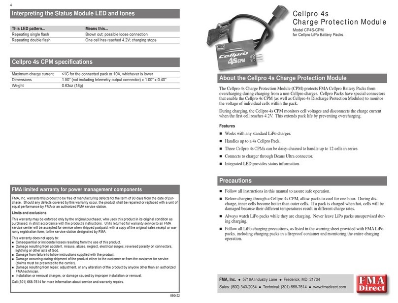
FMA Direct Cellpro 4s User manual

8
060429
FMA limited warranty
FMA, Inc. warrants this product to be free of manufacturing defects for the term of 90 days from the date of
purchase. Should any defects covered by this warranty occur, the product shall be repaired or replaced with a
unit of equal performance by FMA or an authorized FMA service station.
Limits and exclusions
This warranty may be enforced only by the original purchaser, who uses this product in its original condition as
purchased, in strict accordance with the product’s instructions. Units returned for warranty service to an FMA
service center will be accepted for service when shipped postpaid, with a copy of the original sales receipt or
warranty registration form, to the service station designated by FMA.
This warranty does not apply to:
Consequential or incidental losses resulting from the use of this product.
Damage resulting from accident, misuse, abuse, neglect, electrical surges, reversed polarity on connectors,
lightning or other acts of God.
Damage from failure to follow instructions supplied with the product.
Damage occurring during shipment of the product either to the customer or from the customer for service
(claims must be presented to the carrier).
Damage resulting from repair, adjustment, or any alteration of the product by anyone other than an autho-
rized FMA technician.
Installation or removal charges, or damage caused by improper installation or removal.
Call (301) 668-7614 for more information about service and warranty repairs.
Cellpro 4s
Discharge Protection Module
for use with Cellpro LiPo Battery Packs
Model CP4S-DPM-BEC
for ESCs with Battery Elimination Circuits (BECs)
Model CP4S-DPM-OPTO
for ESCs with optical isolation in throttle circuit
FMA, Inc.
5716A Industry Lane
Frederick, MD 21704
Sales: (800) 343-2934
Technical: (301) 668-7614
www.fmadirect.com
About the Cellpro 4s Discharge Protection Module
The Cellpro 4s Discharge Protection Module (DPM) prevents FMACellpro Battery Packs from overdis-
charging in electric-powered radio controlled aircraft. Cellpro Packs have special connectors that enable
Cellpro 4s Discharge Protection Modules (as well as Cellpro 4s Charge Protection Modules) to monitor
the voltage of individual cells within the pack.
About the Cellpro system. Your airborne power supply will be made from two kinds of components:
CellproPack(s). Each pack has a special connector that enables Cellpro components to monitor the
voltage of individual cells within the pack.
Cellpro 4s Discharge Protection Module (DPM) for each Cellpro Pack. During discharge
(ying), the Cellpro 4s DPM monitors individual cells within the connected pack and pro-
vides a warning when voltage gets low. A complex algorithm determines when the rst cell
reaches a preset voltage. At this time, the Cellpro 4s DPM works with your existing ESC to
cut voltage to the motor.
For charging you’ll need one of the following:
Cellpro 4s Charger.
or
BalancePro HD Charger with BalancePro HD-to-CellproAdapter, which automatically bal-
ances each cell and prevents overcharging. Besides providing fast charging, this combination
enables Cellpro Packs to deliver longer life, as well as longer and consistent ight duration.
or
Other LiPo charger and Cellpro 4s Charge Protection Module. This setup prevents over-
charging, but cannot perform cell balancing. Over time, the pack may become unbalanced,
reducing ight duration.
Cellpro 4s DPM features
Works with any Electronic Speed Control (ESC).
Enables use of LiPo batteries with both brushed and brushless ESCs.
Soft cutoff gives you time to set up for landing before battery is depleted.
Handles up to a 4s Cellpro Pack.
Three Cellpro 4 DPMs can be daisy-chained to handle up to 12 cells in series.
Connects to ESC through Deans Ultra connectors.
CP4S-DPM-OPTO only: Optical isolation prevents interference from propagating back to receiver.
Optional LED/Speaker Module provides status information.
Precautions
Read and follow all precautions provided with LiPo packs and chargers.

2 7
Installing the CP4S-DPM-BEC
Note: Use the CP4S-DPM-BEC if your ESC is
equipped with a Battery Eliminator Circuit (BEC)
and
You do not need optical isolation to prevent inter-
ference from propagating back into the receiver.
1. Disable the ESC’s cutoff, or set the cutoff to a
value well below 3V/cell.
2. Connect components (see drawing at right):
a. Attach the ESC’s throttle connector to the
Cellpro 4s DPM’s Throttle Output connector.
b. Attach the DPM’s Throttle Input connector
to the receiver’s throttle channel.
c. If you purchased the optional LED/Speaker
Module, plug it into the DPM.
d. Connect the Cellpro Battery Pack to the
ESC.
CAUTION: Do not install an on/off switch in the
battery negative (black) wire. You can install an
arming switch in the battery positive (red) wire.
However, remove power by disconnecting the
battery from the DPM.
Capacitors, connectors and arcing
FMA recommends connecting the Cellpro 4s DPM
to the ESC using mating Deans Ultra connectors.
Noise reduction capacitors at the motor draw ex-
tremely high currents when battery voltage is applied
to the ESC. This current typically causes arcing
at the pins of the connector completing the circuit.
Here’s the correct procedure for powering up the
ESC:
1. Disconnect the Deans Ultra connector between
the Cellpro 4s DPM and the ESC.
2. Connect the Cellpro Pack to the Cellpro 4s DPM.
3. Connect the Deans Ultra connector to complete
the circuit. Arcing may occur at this connector.
While this procedure doesn’t eliminate arcing, it as-
sures that it happens at the Deans Ultra connector.
Eventually, repeated arcing will degrade the connec-
tor and you’ll need to replace it. That’s not a bad
thing, as the Deans Ultra is both inexpensive and
easy to replace.
–+
Receiver
Throttle
1s to 4s
Cellpro
Battery Pack
Throttle
signal Receiver and
servo power
Cellpro 4s DPM
CP4S-DPM-BEC
Gnd pin
(black)
Optional
LED/Spkr
Module
Throttle
signal
Receiver and
servo power
*Disconnect pack
when not in use.
Leaving pack
connected to DPM
will slowly discharge
pack.
ESC
with BEC
Motor
Driving a motor with Cellpro Packs in parallel
For higher capacity, connect any number of Cellpro Packs in parallel, as shown below. This
example shows CP4S-DPM-OPTOs, which need a separate battery to power the receiver and
servos.
Receiver
Throttle
Battery
Receiver
battery
Throttle signal
Cellpro 4s DPM
CP4S-DPM-OPTO
Ground pin
(black wire)
Optional
LED/Speaker
Module
Opto-isolated
throttle signal
Opto-isolated
throttle signal
Motor
Cellpro 4s DPM
CP4S-DPM-OPTO
FMA CMP-HC-5
Parallel Connector Module
Receiver and
servo power
1s to 4s
Cellpro
Battery Pack
1s to 4s
Cellpro
Battery Pack
–+
ESC with
opto-isolated
throttle circuit

6 3
–+
Receiver
Throttle
1s to 4s
Cellpro
Battery Pack
Throttle signal
Ground pin
(black wire)
Optional
LED/Speaker
Module
Throttle signal
Throttle signal
ESC with
BEC
Motor
Receiver and
servo power
Receiver and
servo power
1s to 4s
Cellpro
Battery Pack
Cellpro 4s DPM
CP4S-DPM-BEC Cellpro 4s DPM
CP4S-DPM-BEC
Driving a motor with Cellpro Packs in series
You can connect up to three Cellpro 4s DPMs for higher voltage systems. Voltage to the ESC is
the sum of the voltages of the Cellpro packs.
Note: If you connect an optional LED and Speaker Module to one Cellpro 4s DPM, you
must also connect one to the other Cellpro 4s DPM to receive correct status.
Wiring alternatives
There are a couple of ways to connect the batteries
to the ESC. On this page, Deans Ultra connec-
tors are soldered directly to the ESC input leads.
You can also use FMA Connector Modules. Use
a CMS-HC-5 to connect up to three Cellpro Packs
in series. Use CMP-HC-5 modules to connect any
number of Cellpro Packs in parallel (as shown on
the next page) for increased capacity.
Installing the CP4S-DPM-OPTO
Note: Use the CP4S-DPM-OPTO if your ESC
has optical isolation in the throttle circuit,
or
When your ESC is equipped with a Battery Elimi-
nator Circuit (BEC) and you need to prevent inter-
ference from propagating back into the receiver.
1. Disable the ESC’s cutoff, or set the cutoff to a
value well below 3V/cell.
2. Connect components (see drawing at left):
a. Attach the ESC’s throttle connector to the
Cellpro 4s DPM’s Throttle Output connector.
b. Attach the DPM’s Throttle Input connector
to the receiver’s throttle channel.
c. Connect a battery to the receiver. This bat-
tery will power the receiver and servos.
d. If you purchased the optional LED/Speaker
Module, plug it into the DPM.
e. Connect the Cellpro Battery Pack to the
ESC.
CAUTION:
Charging Cellpro Packs
FMA recommends that you charge Cellpro
Packs with a BalancePro 6s Charger with
BalancePro HD-to-Cellpro Adapter, or with a
Cellpro 4s Charge Protection Module and an-
other LiPo-compatible charger.
–+
Receiver
Throttle
1s to 4s
Cellpro
Battery Pack
Throttle
signal
Gnd pin
(black)
Optional
LED/Spkr
Module
*Disconnect pack
when not in use.
Leaving pack
connected to DPM
will slowly discharge
pack.
Motor
Battery
Receiver
battery
Opto-isolated
throttle signal
ESC with
opto-isolated
throttle circuit
Cellpro 4s DPM
CP4S-DPM-OPTO

4 5
Setting up the Cellpro 4s DPM
1. Teach the Cellpro 4s DPM about the throttle’s off position. The DPM will function without
completing the following steps; however, it will operate with a hard cutoff rather than a soft
cutoff. Be careful when performing these steps. The motor will turn if you move the
throttle stick.
a. Turn off the ESC and turn off your transmitter.
b. Set Cellpro 4s DPM Switch 2 on (see switch diagram
at right).
c. Move transmitter throttle stick all the way down.
d. Turn on transmitter, then turn on ESC. Don’t move
the throttle stick!
e. Set Cellpro 4s Switch 2 off.
2. Set the low voltage cutoff warning time (Switch 1) to Standard or Short:
Standard is for new batteries. Use this setting when you want highest level of protection
for the pack and longest warning time (motor pulses longer before cutoff) when the pack
reaches cutoff.
Short is for older batteries when you are less concerned about ultimate battery protection
and more concerned about getting the longest ight time. The LVC is slightly lower in
this setting. Although run time will be extended, warning time will also be shortened.
Flying with the Cellpro 4s DPM
Note: Be sure to follow the connection order described in “Capacitors, connectors and
arcing” on page 2 when assembling your power system. When not using the pack, dis-
connect it from the DPM so it won’t slowly discharge.
The Cellpro 4s DPM provides a warning when cells in its connected pack approach the preset
voltage. When the rst cell reaches the preset voltage, the Cellpro 4s DPM pulses voltage to the
ESC (soft cutoff) so you can prepare for landing. Soon after, the motor will stop (hard cutoff).
After the hard cutoff, you may be able to reset the Cellpro 4s DPM by pulling the throttle low
and advancing it again. Restarts are possible, but the number depends on how fast the cell with
the lowest voltage recovers above the minimum operating voltage. When the pack is fully ex-
hausted, there will be no power to the motor.
It’s a good idea to ground-test the entire propulsion system before ying with it. Take it through
a full simulated run and keep pushing it until the motor won’t restart. You’ll get a feel for ying
time, and gain hands-on experience with end-of-run motor behavior.
Standard
Short
On
Off
Low voltage cutoff
warning time Throttle setup
ON
1 2
Interpreting the Status Module LED and tones
This tone... Means this...
Startup song Power applied
Single low tone (same as rst note Brown out; possible loose connection
of startup song)
“Cricket” sound (starts when Cellpro Disconnect Cellpro pack from Cellpro 4s DPM
6s DPM has not detected a throttle signal
from the receiver for two hours)
This LED pattern... Means this... And this happens...
Repeating single ash Low battery warning —
Repeating double ash Low battery, near cutoff Motor pulses
Solid on Battery depleted ESC shuts down*
This tone during a ight
(or other discharge)... Means this... And this happens...
Repeating single tone Low battery warning —
Repeating double tones Low battery, near cutoff Motor pulses
Solid tone Battery depleted ESC shuts down*
*ESC may restart if battery voltage recovers above cutoff.
Troubleshooting
Symptom Solution
Solid tone after connecting to battery Check for dirty node connector or broken wire.
Cellpro 4s DPM specications
Power consumption 10mA from Cellpro Pack
Dimensions 1.15" (not including Throttle Output connector) x 0.82" x 0.43"
Weight 0.26oz (7.3g)
Optional speaker weight 0.14oz (4g)
This manual suits for next models
2
Other FMA Direct Control Unit manuals
