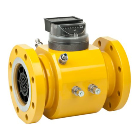
FMG FMR 171 User manual

FMR 171/241/260 QA Installation and Operation Instructions –Page 1 of 20
EN
Installation and Operation Instructions
Rotary Gas Meter Type FMR 171/241/260
WARNING
If there remain any questions or remarks after reading these instructions,
please contact the supplier of this product. Before installing the gas meter
the international, national, as well as local and company regulations related
to this product should be known.
A more extensive manual of this gas meter is available on request.
ENVIRONMENTAL CONDITIONS OF THE METER:
Mechanical class M2 & Electromagnetic class E1
Max. Operating temperature range from -40°C to +70°C.
Meter can be installed in open air.
Avoid direct sunshine on the meter.
Minimal IP-classification of Index: IP54 (splash proof)
INSTRUCTIONS:
1) Check the meter for damage due to transportation and handling. The rotors should
rotate freely.
2) Check the flow direction, as indicated with an arrow on the Pm-
indication label on the meter. In case the flow direction is incorrect, this
can be changed to a reversed flow (horizontal, right to left) by turning
the index plate. For the positions of the Pressure and Temperature
connections see figure 4.
3) The piping on the inlet side of the meter must be clean (free of dirt, welding beads
and pipe scale). It is recommended to install a 100 micron filter upstream of the
meter. For new installations it is recommended to install a wire mesh screen (250
micron) for the first weeks of operation.
4) The meter must be installed free of piping stress.
5) Level the meter within 5mm/m side-to-side and front-to-back
6) TIGHTEN THE FLANGE BOLTS CROSSWISE AND REGULARLY (for the dimensions of the
flange bolts and the applied tightening torque on the different sizes see figure 3).
7) The meter is shipped with empty oil reservoir. Fill the oil reservoir at the front side of
the meter with the supplied oil to the indicated level (see figure 1). For a correct
II 2 G T4

FMR 171/241/260 QA Installation and Operation Instructions –Page 2 of 20
reading of the oil level it should stabilize for a few minutes. To remove or place the oil
plug you need an Allen key.
8) Pressurize the meter with care to avoid overloading. The pressure change should never
exceed 350 mbar/sec.
9) Connect the electrical pulsers in accordance with the connection diagram (see figure
2). The connector is in conformance with IP67 as long as the companion plug or the
protection cap is connected.
10) An indication of the meter condition can be obtained by monitoring the pressure drop
over the meter (Pm- vs. P-point). It is recommended that the pressure drop over a new
meter is measured. This value can be compared to future measurements.
PRECAUTIONS:
1) Never use the meter as a spool piece during welding.
2) The meter must be depressurised before filling or adding oil.
3) Before removing the meter, the oil should be drained.
4) The meter should be transported and stored with the rotor axis horizontal.
5) Use only devices with electrical characteristics as recommended (see connection
diagram figure 2)
6) The maximum tightening torque on the Pressure and Temperature tapping connections
is: 18 Nm. To tighten the swivel nuts; use 2 wrenches to avoid over tighten and
damage the meter body.
7) Avoid mechanical shock during handling and transportation of the meter.
8) Avoid strong magnet fields close to the meter (particular the index), since they can
affect the metrological performance and/or interrupt the pulse generators.
9) Seal all plugs and sight glasses to overcome fraud and/or theft of gas.
10) Lock (two bolts M5) and seal the index after adjusting it in the right position.
all BLUE or TABLET seals are ‘Metrological Seals’; do NOT
remove them
all ORANGE seals are ‘Service Seals’; they can/may be removed
and replaced

FMR 171/241/260 QA Installation and Operation Instructions –Page 3 of 20
NL
Installatie en bedieningshandleiding
Rotor Gas Meter Type FMR 171/241/260
OMGEVINGSCONDITIES VAN DE METER:
Mechanisch klasse M2 en Elektromagnetisch klasse E1
Bedrijfstemperatuur -40°C tot +70°C.
Meter kan in de open lucht worden opgesteld.
Voorkom directe instraling van zonlicht
Minimale IP Klasse van telwerk: IP54, mits aangesloten volgens voorschrift.
INBOUWINSTRUCTIES:
1) Controleer de meter op beschadigingen veroorzaakt door het transport. De rotoren
moeten vrij draaien. In geval van beschadigingen meld dit bij de leverancier van dit
product.
2) Controleer de stromingsrichting zoals aangegeven op de meter (Pm
label met pijl) en sluit de druk- en temperatuursensors aan op de
daarvoor bestemde aansluitingen. Het maximale aanhaalkoppel voor
de druk- en temperatuuraansluitingen is 18 Nm.
3) De in en uitlaat pijpstukken van de meter dienen vrij te zijn van vuil,
roest, lasslakken, etc. Het wordt aanbevolen, om in de eerste weken van gebruik een
250 micron filter te installeren.
4) De meter moet vrij van installatiespanningen geïnstalleerd worden.
5) De meter moet in alle richtingen horizontaal vlak geïnstalleerd worden met een
maximale afwijking van 5mm per meter.
6) HAAL DE FLENSBOUTEN KRUISLINGS EN EVENREDIG aan met een maximaal
aanhaalmoment zoals weergeven in onderstaande tabel.
7) De meters dienen altijd getransporteerd te worden zonder olie in het carter.
Vul het carter met de meegeleverde olie tot het niveau als weergegeven in
onderstaande figuur. Wacht een minuut om het olieniveau te laten stabiliseren.
WAARSCHUWING
Bij vragen of onduidelijkheden na het lezen van de handleiding wordt
verzocht contact op te nemen met de leverancier van het product. Voor
het installeren en in gebruik nemen dienen de van toepassing zijnde
nationale / internationale en bedrijfsregels bekend te zijn. Een meer
uitgebreide handleiding (Engelse taal) is op verzoek verkrijgbaar.
II 2 G T4

FMR 171/241/260 QA Installation and Operation Instructions –Page 4 of 20
8) Breng de meter langzaam (maximaal 350mbar/sec) op druk en voorkom daarmee
overbelasting.
9) Sluit de elektrische contacten aan volgens onderstaand figuur. De connector en het
telwerk hebben een classificatie IP67 zolang het contradeel of de beschermingskap van
de connector zijn aangesloten.
VOORZORGSMAATREGELEN:
1) Gebruik de meter niet als vulstuk bij laswerkzaamheden.
2) Voordat een van de pluggen (olie vulplug, olie aftapplug, HF plug, etc.) van het
voordeksel losgedraaid wordt, dient de druk in de meter afgelaten te worden.
3) Voordat de meter uit de leiding wordt gehaald dient de olie uit het carter af getapt te
worden. Voer de afgetapte olie af volgens geldende milieu wetgeving/richtlijnen.
4) De meter moet met de rotorassen horizontaal getransporteerd en opgeslagen worden.
5) Sluit alleen elektrische apparaten aan met de juiste elektrische eigenschappen (zie
aansluitschema).
6) Voorkom mechanische schokken gedurende het transport en het inbouwen.
7) Voorkom magnetische velden dicht bij de meter. Sterke magnetische velden kunnen de
metrologische eigenschappen van de meter beïnvloeden.
8) Voorkom dat de pluggen en kijkglazen ongeoorloofd geopend kunnen worden in
verband met beïnvloeding van de metrologische eigenschappen en diefstal van gas.
9) Fixeer het telwerk middels de twee M5 bouten aan het voordeksel en verzegel de
afdekplaten.
10) De conditie van de meter kan worden gecontroleerd door regelmatig het drukverschil
te meten over de drukmeetpunten (PM - vs. P punt). Het wordt daarom aanbevolen het
drukverschil over een nieuwe meter te meten. Deze waarde kan worden vergeleken
met toekomstige metingen.
alle BLAUWE of TABLET zegels zijn ‘Metrologische Zegels’;
verwijder deze NIET!
alle ORANJE zegels zijn ‘Service Zegels’; deze kunnen/mogen
worden verwijderd/vervangen.

FMR 171/241/260 QA Installation and Operation Instructions –Page 5 of 20
DU
Installation und Inbetriebsanleitungen
Drehkolbengaszähler Typ FMR 171/241/260
UMGEBUNGSBEDINGUNGEN DES ZÄHLERS:
•Mechanische Klasse M2 und elektromagnetische Klasse E1.
•Max. Betriebstemperatur -40° C bis +70 ° C.
•Das Messgerät kann im Freien installiert werden.
•Direkte Sonneneinstrahlung vermeiden.
•Minimaler IP Klasse Zählerwerk: IP54 sofern nach Vorgaben angeschlossen.
INSTALLATIONSANLEITUNG:
1) Das Rohrleitungs-System, in das der Zähler montiert wird, muss sauber und frei von
Schweissrückständen u.ä. sein.
2) Zählerkontrolle auf Transportschäden und freie Drehbewegung der Rotoren.
3) Transportschäden sind unmittelbar an den Zählerhersteller zu melden.
4) Es wird empfohlen, ein 250 Mikro-Filter (Sieb) zu installieren.
5) Überprüfen Sie die Durchflussrichtung - wie angegeben auf dem Zähler
(Pm Andeutung mit Pfeil) - und schließen Sie Druck- und Temperatur-
Sensoren an die entsprechenden Buchsen (Anschlusspositionen) an. Das
maximale Anzugsdrehmoment für Druck- und Temperaturverbindungen
beträgt 18 Nm. Es wird empfohlen zwei Schlüssel zu verwenden.
6) Bei Zählermontage Strömungsrichtung beachten. Vor Drehung des Zählwerks sollten
zwei verplombte M5-Schrauben auf der linken Seite des Zählwerks entfernt werden.
Drehen Sie das Zählwerk in die richtige Position (Durchflussrichtung). Nach der
Positionierung des Zählwerks müssen die zwei M5-Schrauben wieder verplombt
werden.
7) Der Zähler muss spannungsfrei und waagerecht installiert werden (maximale
Abweichung von 5 mm/m).
Sollten sich nach dem Durchlesen dieser Anleitung Fragen oder Hinweise
ergeben, wenden Sie sich bitte an den Hersteller.
Bei Installation und Anwendung dieser Anleitung sollten nationale- und
internationale Vorschriften bekannt sein.
Ein Handbuch in Englisch steht auf Anfrage zur Verfügung.
II 2 G T4

FMR 171/241/260 QA Installation and Operation Instructions –Page 6 of 20
8) ZIEHEN SIE DIE FLANSCHSCHRAUBEN KREUZWEISE UND REGELMÄSSIG. Das maximale
Drehmoment der Flanschverschraubung ist in einer der folgenden Tabelle dargestellt.
9) Der Zähler wird mit leeren Ölreservoir geliefert. Füllen Sie das Öl-Reservoir an der
Vorderseite des Zählers mit dem mitgelieferten Öl zu dem angegebenen Ebene (siehe
Abbildung 1). Für die richtige Lesung des Ölstands sollte es für ein paar Minuten
stabilisieren. Zum Entfernen oder legen den Öl-Stopfen benötigen Sie einen
Inbusschlüssel.
10) Den Zähler langsam mit Gas befüllen (bis max. 350mbar/s).
11) Verbinden Sie die elektrischen Kontakte gemäß der Abbildung: elektrische Anschlüsse.
Ein Gegenstecker ist dem Gerät beigefügt. Die komplette Steckerverbindung entspricht
der Schutzart IP67.
12) Ein Hinweis auf die Zähler-Bedingung kann durch Überwachung des Druckabfalls über
der Zähler (Pm - vs. P-Punkt) abgerufen werden. Es wird empfohlen, dass der
Druckabfall über einem neuen Meter gemessen wird. Dieser Wert kann mit zukünftigen
Messungen verglichen werden.
MONTAGEHINWEISE / VORSICHTSMASSNAHMEN:
1) Verwenden Sie das Messgerät nicht als Passstück bei Schweißarbeiten.
2) Der Zähler muss vor dem Befüllen oder Hinzufügen von Öl drucklos sein.
3) Bevor der Zähler aus dem Netz genommen wird (drucklos), muss das Öl abgelassen
werden. Bei Entsorgung des Öls müssen die landesspezifischen Umweltrichtlinien
beachtet werden.
4) Der Zähler sollte in waagerechter Position transportiert werden.
5) Schließen Sie elektrische Geräte nach den entsprechend Vorschriften und der
Werksempfehlung an (siehe elektrische Anschlüsse).
6) Vermeiden Sie mechanische Erschütterungen und starke Magnetfelder (Magnetfelder
beeinflussen die messtechnischen Eigenschaften).
7) Verplomben Sie alle Schrauben (Diebstahlsicherung von Gas).
Jede BLAUE Plombe/Schlagsiegel ist ein
eichamtliche Versiegelung und darf NIEMALS
entfernt werden!
Jede ORANGE Plombe ist eine Werksversiegelung
und darf durch Ihre eigenen Werksplombe ersetzt
werden!

FMR 171/241/260 QA Installation and Operation Instructions –Page 7 of 20
Calculation HF value
for optical testing
(only for UNI-directional version)
HF [imp/m³] = 1000 / ( Volume [m³] * 2 )
the value of the volume (V) is mentioned on
the nameplate of the meter.
(in testbench setup: n cycle = 2)
Berekenen impulswaarde
Optische HF Sensor
(alleen bij UNI-directionele versie)
HF [imp/m³] = 1000 / ( Slagvolume [m³] * 2 )
De waarde van het slagvolume (V) staat op
de typeplaat van de meter.
(in testbank setup: n cycle = 2)
Berechnung Impulswertigkeit
Optischer HF Sensor
(nur bei Universal Ausführung)
Für Prüfzwecke ist eine optische Schnittstelle vorgesehen.
Die zu verwenden Impulswertigkeit wie folgt berechnen:
Impuls (imp/m³) = 1000 / Kammervolumen * 2
Das Kammervolumen steht auf den Typschild. Um maximale
Messsicherheit bei Zeitmessung zu gewährleisten, muss
jeder zweite Impuls bei Start / Stopp registriert werden.
Fig. 1
OIL VOLUMES (INDICATIVE)
OLIE VOLUMES (INDICATIEF)
ÖLSTANDANZEIGE (INDIKATIV)
Length
Front
view
Horizontal
position
Vertical
position
= pressure tapping
= Temperature tapping
= fill-/drain plug = oil sight glass
= Optical HF (non-standard feature)
171
37 cc
99 cc
241
37 cc
99 cc
241/260
119 cc
266 cc
Level –Oil Sight Glass
Fig. 2
Max
Min
3mm
mmm
mmm
3mm
mm
M
e
n
i
s
t
s
t
r
a
a
t
5
c
,
7
0
9
1
Z
Z
D
i
n
x
p
e
r
l
o
,
T
h
e

FMR 171/241/260 QA Installation and Operation Instructions –Page 8 of 20
Fig. 3 FLANGE CONNECTIONS (threading size + threading length in body)
FLENS AANSLUITINGEN (schroefdraad grootte / lengte in huis)
FLANSCH ANSCHLÜSSE (Gewinde / Gewindelänge im Gehäuse)
Inlet Size
1½”
DN040
2”
DN050
3”
DN080
Flange conn.
ANSI
DIN
ANSI
DIN
ANSI
DIN
Thread (T)
1/2"UNC
M16
5/8"UNC
M16
5/8"UNC
M16
max. Length (L) mm
16-24
16-24
16-24
16-24
16-24
16-24
Inlet Size
4”
DN100
6”
DN150
Flange conn.
ANSI
DIN
ANSI
DIN
Thread (T)
5/8"UNC
M16
3/4"UNC
M20
max. Length (L) mm
16-24
16-24
20-30
20-30
Fig. 4 TIGHTENING TORQUES OF FLANGE BOLTS (in opposite pairs)
AANDRAAIMOMENTEN FLENS BOUTEN (kruislings aandraaien)
DREHMOMENTEN FLANSCH BOLTZEN (über Kreuz anzuziehen)
Inlet Size
1½”
DN040
2”
DN050
3”
DN080
Flange conn.
ANSI
DIN
ANSI
DIN
ANSI
DIN
nominal Torque
40 Nm
40 Nm
50 Nm
50 Nm
40 Nm
40 Nm
max. Torque
50 Nm
50 Nm
60 Nm
60 Nm
50 Nm
50 Nm
Inlet Size
4”
DN100
6”
DN150
Flange conn.
ANSI
DIN
ANSI
DIN
nominal Torque
55 Nm
55 Nm
70 Nm
70 Nm
max. Torque
65 Nm
65 Nm
80 Nm
80 Nm

FMR 171/241/260 QA Installation and Operation Instructions –Page 9 of 20
Fig.5 (EN) POSITION OF PRESSURE AND TEMPERATURE CONNECTIONS
(NL) POSITIE VAN DRUK EN TEMPERATUUR AANSLUITINGEN
(DU) POSITIONEN VON DRUCK UND TEMPERATUR ANSCHLUSSE
The pressure reference connection (Pm) is always located on the INLET of the rotary meter.
De referentiedrukaansluiting (Pm) zit altijd aan de INLAATzijde van de rotormeter.
Den Referenzdruckanschluss (Pm) ist immer am EINGANG der Drehkolbengaszähler.
P + T connections: on front cover / op deksel (voorzijde) / am vorderseite der Zähler
T Pm T
left-right / top-bottom
links-rechts / boven-onder
links-rechts / oben-unten
T Pm T
right-left / bottom-top (not recommended)
rechts-links / onder-boven (niet aanbevolen)
rechts-links / unten-oben (nicht bevorzugt)
P + T connections: on body / op het huis / auf Gehäuse der Zähler
T Pm T
left-right / top-bottom
links-rechts / boven-onder
links-rechts / oben-unten
T Pm T
right-left / bottom-top (not recommended)
rechts-links / onder-boven (niet aanbevolen)
rechts-links / unten-oben (nicht bevorzugt)
P + T connections: UNI-directional versions / UNI-directionele versies / Universal
Ausführung
T Pm T
T Pm T

FMR 171/241/260 QA Installation and Operation Instructions –Page 10 of 20
Introduction to the universal index
This is the standard version and it has two 8-digit mechanical roller
indexes. Depending on the flow direction, one index will be covered.
The index can be rotated in any position, so that the meter can be
used in any position. Two separate LF pulse signals can be
monitored by a integrated male binder connection in the index.
Introduction to the basic index
Optional is the basic index. This is a simplified version of the universal
index. It is suitable for only one flow direction. It is equipped with a
male binder to monitor the LF pulses.
Introduction to the instrument drive
This is a standalone unit to provide a mechanical input into for
example a volume corrector. To rotate the instrument drive, see
instructions below.
Rotating the index
To rotate the Universal index or the instrument drive it is required to remove the two M5 screws.
Therefore the service sealing will have to be removed. After the index has been rotated in the correct
position, the two M5 screws should be mounted and the service sealing will have to be applied again.
(Note: The position of the M5 screws may vary due to customer standards.)
The basic index can always be rotated in the desired position.
Index: Universal –Basic –Instrument drive

FMR 171/241/260 QA Installation and Operation Instructions –Page 11 of 20
Sensor section
Installation
Commissioning
Service
WARNING
A sensor Assy may only be connected and operated by trained and qualified staff,
which must have knowledge of and have verified the protection classes, directives
and regulations concerning electrical equipment designed for use in explosive
atmospheres.
The approval expires if the device is repaired or modified by a person other than
the manufacturer.
Do not install the device in a dust flow and avoid build-up of dust deposits.
Avoid static charging. Please only clean the device with a damp cloth.
If connection cables could be subject to mechanical damage, they must be
protected accordingly.
Connection cables must be shielded against strong electro-magnetic fields
Disconnect power before proceeding with any work on this equipment
Hazardous voltage can cause electrical shock and burns. Electrical plugs and
sockets shall be:
a) interlocked mechanically, so that they cannot be separated when the contacts
are energized and the contacts cannot be energized when the plug and socket are
separated, or
b) fixed together by means of special fasteners and the device marked with the
separation marking as required “WARNING – DO NOT SEPERATE WHEN
ENERGIZED”
Sensor: 3700 REED - 3710 MSR - 3720 Wiegand
Introduction to the 3700 Reed Assy
The 3700 Reed Assy can be used in FMG gas meters which are fitted with a
mechanical index. The device will provide two electrical low frequency pulse
outputs and one electrical magnetic tamper status output for use with
auxiliary electronic equipment.
Introduction to the 3710 MSR Assy
The 3710 MSR Assy can be used in FMG gas meters which
are fitted with a mechanical index. The device will
provide two electrical low frequency pulse outputs and
one electrical magnetic tamper status output for use with
auxiliary electronic equipment.
3710 in LC index 3710 in Std Index
Introduction to the 3720 Wiegand Assy
The 3720 Wiegand Assy can be used in FMG gas meters which are
fitted with a mechanical index. The device provides two low frequency
solid state pulse outputs and one magnetic tamper status output for
use with auxiliary electronic equipment.

FMR 171/241/260 QA Installation and Operation Instructions –Page 12 of 20
Intended use in explosive atmospheres
The Assy fulfills the requirements of the ATEX directive 94/9/EC and can be used in
explosive atmospheres according the European normative documents EN60079-0 and
EN60079-11 (Ex i).
CAUTION
Electrical
equipment
for use in
explosive
atmospheres
Electrical
protection
concept
EC Type Examination
Certificate(s)
Ingress
Protection
Ambient
Temp.
Range
II 2 G
Ex ia IIC
T4…T6 Gb
Baseefa11ATEX0280X
IP20
or IP67
-40°C ≤
Tamb
≤ +70°C
Please observe the max. admissible electrical ratings
for the applicable temperature classes.
3700/3710 ASSY
Intrinsically safe input parameters
Baseefa11ATEX0280X Issue 1
Temp.
Class
Ui
(V)
Ii
(mA)
Pi
(mW)
Ci
Li
T4
51
35
700
0
0
T5
51
35
400
0
0
T6
51
35
80
0
0
Each circuit 1&4, 2&5, 3&6 may be connected to linked
(multi-channel single IS source) or separate intrinsically
safe sources which are certified [Ex ia IIC] such that the
series or parallel combinations of all 3 channels do not
exceed 51V, 35mA and 700mW(T4), 400mW(T5) and
80mW(T6).
Please observe the max. admissible electrical
ratings for the applicable temperature classes.
3720 WIEGAND ASSY
Intrinsically safe input parameters
Baseefa11ATEX0280X Issue 1
Temp.
Class
Ui
(V)
Ii
(mA)
Pi
(mW)
Ci
Li
T4
51
35
700
0
0
T5
51
35
300
0
0
T6
51
35
80
0
0
3700 REED ASSY
(Potted Enclosure)
47R
47R
47R
LF 1
LF 2
Tamper
8.2V < 5 mA
Control Circuit
(EN60947-5-6)
Ri=1k
Ri=1k
Ri=1k
1
4
2
5
3
6
3710 MSR ASSY
47R
47R
47R
LF 1
LF 2
Tamper
8.2V < 5 mA
Control Circuit
(EN60947-5-6)
Ri=1k
Ri=1k
Ri=1k
1
4
2
5
3
6

FMR 171/241/260 QA Installation and Operation Instructions –Page 13 of 20
Each output circuit 1&4, 2&5, 3&6 may be connected to linked (multi-channel single IS
source) or separate intrinsically safe sources which are certified [Ex ia IIC] such that the
series or parallel combinations of all 3 channels do not exceed 51V, 35mA and 700mW(T4),
300mW(T5) and 80mW(T6). Be aware that the two Wiegand Sensor outputs share a
common ground!
Sensor: 4000 HF Sensor Assy
Introduction to the 4000 HF Sensor Assy
The 4000 HF Sensor Assy can be (optionally) used with FMG gas meters. The device provides
a dual high frequency (HF) pulse output (Acc. NAMUR, EN60947-5-6) suitable for gas volume
measurement. The dual pulse output is fase-shifted suitable for direction discrimination
and/or use with auxiliary gas measurement equipment.
Intended use in explosive atmospheres
The 4000 HF Sensor Assy fulfills the requirements of the ATEX directive 94/9/EC and the
EMC directive 2004/108/EC and can be used in explosive atmospheres according the
European normative documents EN60079-0, EN60079-11 and EN60079-26.
CAUTION
Electrical
equipment
for use in
explosive
atmospheres
Electrical
protection
concept
EC Type Examination
Certificate(s) for
embedded sensor:
Manufacturer: TURCK
Type: BIM-EH6,5-
2AY1/S1236 0,5m
Ingress
Protection
Ambient Temp.
Range
II 1 G
or
II 2 G
Ex ia IIC
T4…T6 Ga
or
Ex ia IIC
T4…T6 Gb
KEMA 04 ATEX 1152X
IP67
See table
Temp.
Classes &
Intrinsically
Safe Circuit
Parameters
4000 HF Sensor - Temperature Classes and Intrinsically Safe Circuit Parameters
Min. Amb.
Temp.
Max.
Amb.
Temp.
Category
Temp.
Class
Pi *1
(mW)
Ui *2
(VDC)
Ii *2
(mA)
Li *2
(µH)
Ci *2
(nF)
-40°C
+100
°C
II 2 G
T4
200
20
60
350
180
+80 °C
II 1 G, II 2 G
T4
200
+85 °C
II 2 G
T5
80
+80 °C
II 1 G, II 2 G
T5
80
+70 °C
II 1 G, II 2 G
T5
200
+70 °C
II 1 G, II 2 G
T6
80
+60 °C
II 1 G, II 2 G
T6
150
Note 1
Parameter Pi is applicable for the combined sensor circuits (1A and 1B)
Note 2
Parameters Ui, Ii, Ci and Li apply per sensor circuit (1A or 1B)
Please observe the max. admissible electrical ratings for the applicable temperature classes.

FMR 171/241/260 QA Installation and Operation Instructions –Page 14 of 20
An industrial IP67, M12 4-pin male socket (A-type coded
acc. EN 61076-2-101) is provided for external signal
connections. The M12 metal shell of the output socket
is electrically connected to the gas meter body which
should in gas installations be connected to (skid) earth
potential. The M12 connector nut should be tightened
with a preset torque of 0.4 Nm to guarantee IP67 ingress
protection.
1B
1A 1(+)
2(+)
4(-)
3(-)
WH
BK
BN
BU
Model 4000 HF Sensor Assy
PE

FMR 171/241/260 QA Installation and Operation Instructions –Page 15 of 20

FMR 171/241/260 QA Installation and Operation Instructions –Page 16 of 20

FMR 171/241/260 QA Installation and Operation Instructions –Page 17 of 20
Declaration of Conformity
This “Declaration of Conformity“ complies with the European Standards
-NEN-EN-ISO/IEC 17050-1:2010, Conformity assessment - Supplier's declaration of conformity –Part
1 “General Requirements” and where applicable,
-NEN-EN-ISO/IEC 17050-2:2004, Conformity assessment - Supplier's declaration of conformity –Part
2 “Supporting documentation”.
We: Flow Meter Group B.V.
Meniststraat 5c, 7091 ZZ Dinxperlo, The Netherlands
declare under our sole responsibility that the product(s)
Product: Rotary Gas Meter
Type: FMR 171 + FMR 241 + FMR 260
to which this declaration relates are in conformity with the relevant sections of the following standard(s)
EN12480 ASME B31.8 ASME VIII Div. 1 EN 1127-1 EN 13463-1
EN 13463-5 EN 60079-0 EN 60079-11 EN 60079-26
and where applicable following the provisions of EU Directive(s)
Pressure Equipment Directive (97/23/EC)
Conformity assessment body involved for Annex III (Module B + D):
Lloyd’s Register Verification Limited
71 Fenchurch Street, London EC3M 4BS, United Kingdom, NB number: 0038
Certificate Number / marking:
9004693 / 0038
ATEX 95 (94/9/EC)
Conformity assessment body involved for Annex VIII (Module A+):
Lloyd’s Register Verification Limited
71 Fenchurch Street, London EC3M 4BS, United Kingdom, NB number: 0038
Marking:
II 2 G T4
Signature:
Name: Paul Hoeks
Position: CEO Flow Meter Group B.V.
Dinxperlo, 7 November 2012

FMR 171/241/260 QA Installation and Operation Instructions –Page 18 of 20
This page intentionally left blank.

FMR 171/241/260 QA Installation and Operation Instructions –Page 19 of 20
This page intentionally left blank.

FMR 171/241/260 QA Installation and Operation Instructions –Page 20 of 20
Notice of Rights:
This document is property of Flow Meter Group.
Reproduction, utilization or disclosure to third parties
in any form whatsoever is not allowed
without written consent of the proprietor.
document: 90-200-0000012rev003
FLOW METER GROUP
Meniststraat 5c, 7091 ZZ Dinxperlo, The Netherlands
+31 (0)315 651 556 +31 (0)315 651 488
info@flowmetergroup.com www.flowmetergroup.com
This manual suits for next models
2
Table of contents
Other FMG Measuring Instrument manuals
