Model F53 Flow Monitor/Totalizer (universal-mount 1/2 DIN) Rev. 1-201
10
TABLE OF CONTENTS (continued)
SECTION 3 ADJUSTING DISPLAY CONTRAST.............................................................36
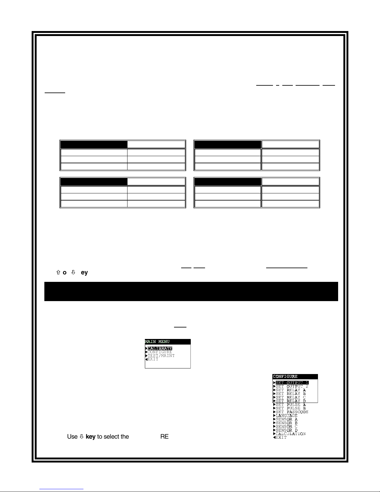
SECTION 4 ANALYZER CONFIGURATION
4.1 Selecting LANGUAGE to Operate Analyzer..........................................37
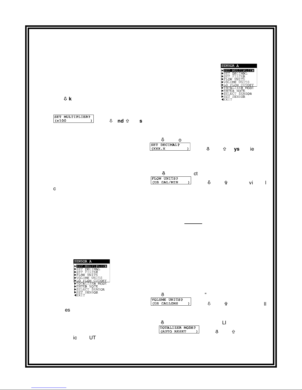
4.2 Configuring Sensors (A, B, C, and D):
SET MULTIPLIER (for displayed flow rate).................................38-39
SET DECIMAL (for displayed flow rate)...........................................39
SET FILTER Time.......................................................................39-40
Select FLOW UNITS (for displayed flow rate) ............................40-41
Select VOLUME UNITS (for displayed volume)...............................41
Set LO FLOW CUTOFF Limit ..........................................................42
Select TOTALIZER MODE (auto or manual reset) .....................42-43
ENTER NOTE (top line of MEASURE screen).................................43
SELECT SENSOR Type .............................................................43-44
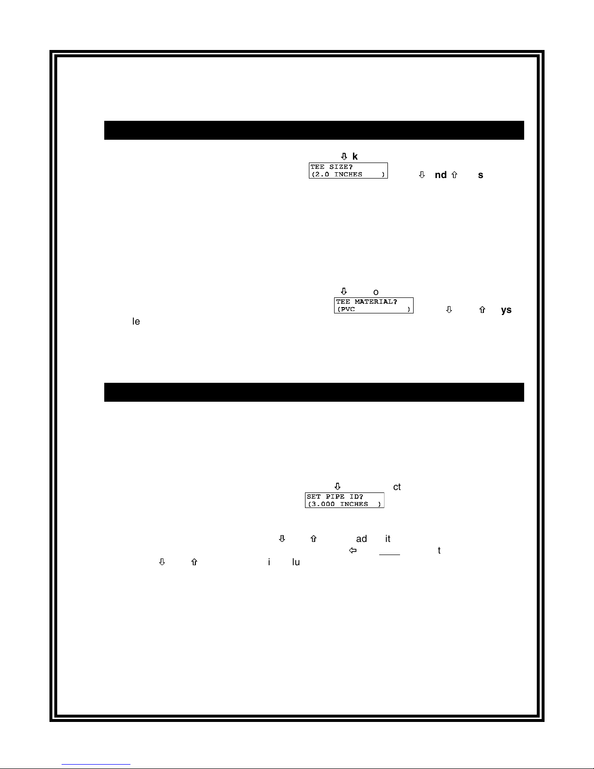
SET SENSOR Data:
GLI Tee Mount -- Select TEE SIZE and TEE MATERIAL......44-45
GLI Pipe Mount -- SET PIPE ID..................................................46
Non-GLI Sensor -- SET SLOPE and SET OFFSET Values......47-48
4.3 Configuring CALCULATION Measurement:
SET VARIABLE X ............................................................................49
SET VARIABLE Y ............................................................................50
SET FORMULA (X/Y, X-Y, X+Y, or [X/Y] x 100) ..............................50
Select DISPLAY FORMAT (decimal and multiplier)....................51-52
4.4 Configuring Analog Outputs (1 and 2):
SET PARAMETER (representation) ...........................................53-54
SET 0/4 mA and 20 mA VALUES................................................54-55
SET FILTER Time............................................................................55
Select SCALE 0 mA/4 mA (low endpoint) ........................................55
4.5 Configuring Relays (A, B, C, and D):
SET PARAMETER (representation) ...........................................56-57
SET FUNCTION Mode (alarm, control or status).............................57
ACTIVATION (configuration values)...........................................58-59
4.6 Configuring Pulse Outputs (A and B):
SET PARAMETER (representation) ................................................60
SET VOLUME Increment ............................................................60-61
Set PULSE DURATION ...................................................................61
4.7 SET PASSCODE (feature enabled or disabled) ...................................62
4.8 Configuration Setting Summary (ranges/choices and defaults) .......63-65
SECTION 5 ANALYZER CALIBRATION
5.1 Important Information ............................................................................66
5.2 OFFSET BY or SET TO Calibration Adjustment ..............................67-68
5.3 Analog Outputs (1 and 2) Calibration...............................................68-69