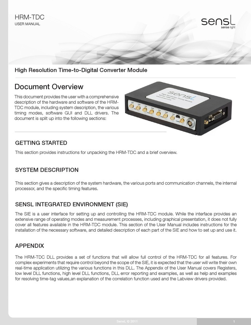
FMI P20D RTK User manual

www.feymani.com
P20D RTK
Positioning and Heading
Module
V1.4

www.feymani.com
REVISIONS
Version
Release notes
Dates
R1.0
Beta version
2022-12-09
R1.1
Add protocols GPHPR, GPIMU
2023-03-14
R1.2
Add protocols HDT, ROT, SXT
2023-03-23
R1.3
Add protocol FMI, add dual antenna installation notes, add
module picture
2023-06-06
R1.4
Add support for 10Hz RTK, enable 3 UART outputs
2023-09-04

www.feymani.com
Table of Contents
1. Introductions...............................................................................................................1
2. Features.......................................................................................................................1
3. Parameters...................................................................................................................2
4. Pin definition.............................................................................................................. 3
5. Antenna features ......................................................................................................... 4
6. Commands.................................................................................................................. 5
7. Packaging....................................................................................................................7
8. Manufacturing Requirements .....................................................................................8
9. Message protocols ...................................................................................................... 9

www.feymani.com
1
1. Introductions
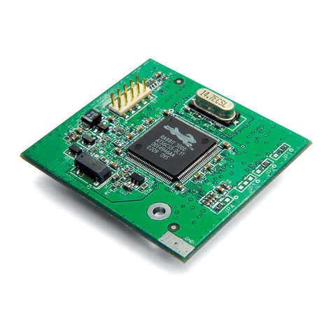
P20D is a high-precision GNSS RTK positioning and heading module. It can simultaneously
track multiple frequencies of all GNSS constellations (GPS, BDS2, BDS3, GALILEO, GLONASS,
QZSS), and the module can perform on-chip RTK positioning and dual-antenna heading
calculation. P20D has integrated an industrial 6-axis IMU sensor that can maintain correct heading
and attitude information for harsh GNSS signal reception environment.
P20D is a perfect choice for high-precision navigation and Positioning applications such as
UAV, machine control, precision agriculture and marine, that demands the highest stability and
integrity in heading and attitude.
2. Features
•12nm technology, most advanced in industry.
•Supports RTK between master and slave antenna for heading operation, with antenna
separation as close as 5 cm
•21 mm x 16 mm x 2.6 mm, the smallest integrated heading module
•Lowest power RTK&heading module (100mW peak power) in the world
•Supports dual mode operation (base station/rover mode)
•Full constellations and multiple frequencies

www.feymani.com
2
3. Parameters
Category
Performance index
Receive Type
GPS/QZSS: L1/L5
BeiDou: B1I/B2a
GALILEO: E1/E5a
GLONASS: G1
Nav. update rate
RTK: 1Hz/2Hz/5Hz/10Hz
IMU: 50Hz/100Hz
sensitivity
Tracking & Nav.
-165dBm
Reacquisition
-160dBm
Capture sensitivity
-148dBm
Acquisition
cold starts
27s
5s with AGNSS
hot starts
1s
Heading accuracy
0.2 degrees/1m baseline
Position accuracy
1cm + 1ppm
Altitude accuracy
2cm + 1ppm
Operational limits
Velocity
515m/s
Altitude
18km
Interface
UART
3 (default baud rate 115200)
PPS
1
Protocols
NMEA 0183
RTCM 3.3
Electrical data
Supply voltage
2.8V~4.3V (3.3V recommended)
RF Antenna voltage
3.3V
Serial voltage
2.8V
PPS
2.8V
power
30mA*3.3V
Operating temp
-40°C to 85°C
Storage temp
-40°C to 90°C
humidity
95% non-condensing
Package
21 mm x 16 mm x 2.6 mm

www.feymani.com
3
4. Pin definition
Pin NO
name
I/O
Descriptive
1
GND
-
Ground
2
ANT1_IN
I
GNSS antenna signal input (main antenna)
3~4
GND
-
ground
5~11
NC
-
vacancy
12
WIT
I/O
USB data
13
DIR
I
USB power
14
ERR_STAT
O
Abnormal status output, active high
15
PVT_STAT
O
PVT positioning indication, active high
16
RTK_STAT
O
RTK position indication, active high
17
RXD0
I
Serial 0 receive
18
TXD0
O
Serial 0 Transmit
19
RXD1
I
Serial port 1 receive
20
TXD1
O
Serial port 1 Transmit
21~22
NC
-
vacancy
23
VCC
POWER
Voltage supply 3.3V
24
VCC
POWER
Voltage supply 3.3V
25~26
NC
-
vacancy

www.feymani.com
4
27
TXD2
O
Serial port 2 Transmit
28
RXD2
I
Serial port 2 receive
29
NC
-
vacancy
30
PPS
O
second pulse (physics)
31
NC
-
vacancy
32
RTC_EINT
I
Low Power Wakeup
33
RESET
I
system reset
34~35
GND
-
ground
36
ANT2_IN
I
GNSS antenna signal input (from antenna)
37
GND
-
ground
38~40
NC
-
vacancy
41
GND
-
ground
42
NC
-
vacancy
43
GND
-
ground
44
NC
-
vacancy
45
GND
-
ground
46~48
NC
-
vacancy
5. Antenna features
Parameters
min
max
unit
Input Gain
18
23
dB

www.feymani.com
5
6. Commands
AT+GPGGA=n
Select serial port to output GGA every n epochs
AT+GPRMC=n
Select serial port to output RMC every n epochs
AT+GPSAT=n
Select serial port to output GSV/GSA every n epochs
AT+GPGST=n
Select serial port to output GST every n epochs
AT+GPGLL=n
Select serial port to output GLL every n epochs
AT+GPVTG=n
Select serial port to output VTG every n epochs
AT+GPZDA=n
Select serial port to output ZDA every n epochs
AT+GPHDT=n
Select serial port to output HDT every n epochs
AT+GPROT=n
Select serial port to output ROT every n epochs
AT+GPTHS=n
Select serial port to output THS every n epochs
AT+GPSXT=n
Select serial port to output SXT every n epochs
AT+GPFMI=n
Select serial port to output FMI every n epochs (upgrade to new firmware version
required)
AT+GPHPR=n
Select serial port to output HPR every n epochs(1~100Hz)
AT+GPIMU=n
Select serial port to output IMU every n epochs(1~100Hz) (1~100Hz)
AT+IMU_RATE=100
Set internal IMU update frequency (50Hz, 100Hz) Default 50Hz
AT+IMU_ANGLE=x,y,z
Setting the module mounting angle, see the module mounting help manual for
details, reboot required
AT+YAW_ANGLE=0,0,z
Set the dual antenna mounting rotation angle (z is the rotation angle) (following a
right-handed coordinate system, with the thumb pointing in the positive direction
of the z-axis, clockwise is positive, and the dual antenna direction is steered in the
direction of carrier motion)
AT+RTCM=1/0
Output RTCM3 Obs Data (1:open,0:close)
AT+NAVI_RATE=1
Set Nav update rate 1Hz
Support 1/2/5Hz, need cold restart
AT+UARTOFF=UART0/1
Stop all output of the select serial port
AT+BAUD_RATE=115200
Set the serial port baud rate
Need cold restar
(supports 460800, 921600)
AT+READ_PARA
Read mode parameters
AT+THIS_PORT
Read the current serial port number

www.feymani.com
6
Notes on module and dual antenna installation:
1. P20D has an integrated imu, therefore the module needs to be rigidly installed with the host
vehicle. There should be no relative motion between P20D module and the master/slave antennas.
2. The default orientation when installing the module is where the arrow on the module label is
pointing (as shown in the picture below) towards the direction of the carrier's movement, with the
top of the module pointing towards the sky and the back of the module pointing towards the ground.
3. Configuration Commands exist to allow for different orientations when the above
installations can not be made.
AT + IMU_ANGLE = x,y,z for the module mounting angle configuration (you can refer to the
P20X module mounting user manual)
4. If the dual-antenna direction is not consistent with the forward direction of the vehicle, it is
necessary to adjust the dual-antenna angle to ensure that it is consistent with the direction of the
vehicle, send the command AT+YAW_ANGLE=0,0,z to configure (z is the angle of rotation,
following the right-handed coordinate system, with the thumb pointing in the positive direction of
the z-axis, and the clockwise direction is positive, and the direction of the dual-antenna is shifted
towards the direction of the vehicle movement)
AT+WARM_RESET
Warm restart
AT+COLD_RESET
Cold restart (some commands require Cold restart to take effect)
AT+RTC_MODE=n
enter standby mode, n is the time (in seconds) to keep the RTC in sleep mode, the
Minimum valid time is 10 seconds, if set to 0, hardware wakeup is required.
AT+NMEA_HEAD=0/1
0: statements such as GGA begin with GN, 1: begin with GP (default 0)
Default baud rate 115200, commands end in \r\n. Compatible P20M Command Format

www.feymani.com
7
7. Packaging
Symbol
Min.(mm)
Typ.(mm)
Max.(mm)
A
20.80
21.00
21.50
B
15.80
16.00
16.50
C
2.40
2.60
2.80
D
2.78
2.88
2.98
E
0.95
1.05
1.15
F
1.55
1.65
1.75
G
1.17
1.27
1.37
H
0.70
0.80
0.90
K
1.40
1.50
1.60
M
4.10
4.20
4.30
N
3.70
3.80
3.90
P
2.05
2.10
2.15
R
0.90
1.00
1.10

www.feymani.com
8
8. Manufacturing Requirements
Furnace Temperature Schematic
Warm-up phase:
Temperature rise rate: max 3°C/S. If the temperature rise is too fast, it may result in a larger
paste slump.
Preheating time: 60~120 S. Insufficient preheating will produce large solder balls, on the
contrary, if preheating is too long, solder balls will be gathered and produced.
Termination temperature: 150°C to 200°C. Too low a temperature and some areas with a high
amount of hot melt will not melt.
Heating-Reflow stage:
Liquid temperature above 217°C. Avoid a sudden rise in temperature, which may cause the
material to collapse.
Time over 217°C: 40-60S.
Peak temperature: 245°C.
Cooling phase:
Cooling control mainly avoids solder becoming more brittle and possible mechanical tension
in the solder.
Cooling rate: max 4°C/S

www.feymani.com
9
9. Message protocols
(1) GPHPR
$GPHPR,<1>,<2>,<3>,<4>,<5>,<6>,<7>,<8>,<9>*<10><CR><LF>
<1> UTC time in the format hhmmss.sss
<2> Tow seconds in a week
<3> Roll angle (°)
<4> Pitch angle (°)
<5> Heading angle (°)
<6> Standard deviation of roll angle
<7> Standard deviation of pitch angle
<8> Standard deviation of heading angle
<9> Synchronized age
<10> heteroskedastic checksum
Example statement:
$GNHPR,054913.004,193771.004,-0.391,0.009,69.434,0.123,0.123,0.018,0.204*5D
(2) GPIMU
$GPIMU,<1>,<2>,<3>,<4>,<5>,<6>,<7>,<8>*<9><CR><LF>
<1> UTC time in the format hhmmss.sss
<2> x-axis acceleration (g)
<3> y-axis acceleration (g)
<4> z-axis acceleration (g)
<5> Gyro x-axis orientation (°/s)
<6> Gyro y-axis orientation (°/s)
<7> Gyro z-axis orientation (°/s)
<8> Sensor temperature (°C)
<9> heteroskedastic checksum
Example statement:
$GPIMU,054752.002,0.000,0.007,-1.032,-0.003,0.053,-0.016,26.00*59
(3) GNSXT
$GNSXT,<1>,<2>,<3>,<4>,<5>,<6>,<7>,<8>,<9>,<10>*<11><CR>& LF>
<1> utc time hhmmss.sss
<2> Distance from antenna to main antenna (m)
<3> North-facing position with the main antenna as origin (m)
<4> Easterly position with the main antenna as origin (m)
<5> Zenithward position with the main antenna as origin (m)
<6> Standard deviation of the northward position
<7> Standard deviation of the eastward position

www.feymani.com
10
<8> Standard deviation of zenith to position
<9> Number of satellites used for settlement from antennas
<10> Localization quality from antenna (0: not available, 4: fixed solution)
<11> checksum
Example statement:
$GNSXT,032423.200,9.903,3.484,9.270,-0.003,0.012,0.022,0.015,31,4*7B
(4) GPFMI
$GPFMI,<1>,<2>,<3>,<4>,<5>,<6>,<7>,<8>,<9>,<10>,<11>,<12>.
<13>,<14>,<15>,<16>,<17>,<18>,<19>,<20>,<21>,<22>,<23>[,<E1&
gt;~<E10>]*<24><CR><LF>
<1> UTC time in the format hhmmss.ss. ss
<2> Week number.
<3> Time of week, seconds of week, in the format (ss.mmm)
<4> Latitude in degrees. Positive numbers are north latitude, negative numbers are south
latitude
<5> Longitude, in degrees. Positive numbers are east longitude, negative numbers are west
longitude.
<6> Elevation, in meters
<7> Standard deviation of latitude, in meters
<8> Standard deviation of longitude, in meters
<9> Standard deviation of elevation, in meters
<10> Velocity eastward in meters per second (m/s)
<11> Velocity northward in meters per second (m/s)
<12> Velocity in zenith direction, in meters per second (m/s)
<13> Standard deviation of horizontal velocity, in m/s
<14> Angle of heading, in degrees
<15> Pitch angle, in degrees
<16> Traverse roll angle, in degrees
<17> Standard deviation of heading angle, in degrees
<18> Standard deviation of pitch angle, in degrees
<19> Standard deviation of roll angle, in degrees
<20> Baseline distance in meters
<21> Number of satellites visible from the antenna
<22> The number of observations fixed throughout the carrier week is only meaningful for
fixed solutions
<23> Positioning quality indication, 0=invalid solution, 1=single point solution, 2=differential
solution, 4=fixed solution, 5=floating point solution, 6=inertial guidance solution
If you set the FMI statement to expand, you will append 10 expansion fields
<E1> Fixed solution reference Ratio

www.feymani.com
11
<E2> Number of fixed-solution AR double-difference fuzzy degrees
<E3> Carrier-to-noise ratio average
<E4> Number of carrier non-integer observations
<E5> Number of delta observations
<E6> Reserved
<E7> Reserved
<E8> Reserved
<E9> Reserved
<E10> Reserved
<24> heteroskedastic checksum
Sample Statement (with Extended Fields)
$GPFMI,092900.20,2248,466158.200,42.06414612,106.22805621,154.305,0.0077,0.0068,0.0
166,-0.006,0.005,0.033,0.012,0.00,0.00,0.00, - 1.0000,-1.0000,-
1.0000,185.578,38,40,4,1.74,19,43,,,,,,,*4C
Table of contents
Other FMI Control Unit manuals
