manuals.online logo
Brands
  1. Home
  2. •
  3. Brands
  4. •
  5. FMI
  6. •
  7. Indoor Fireplace
  8. •
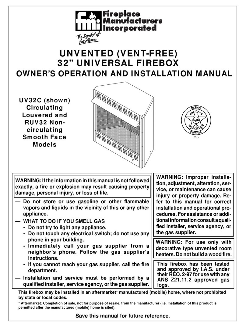
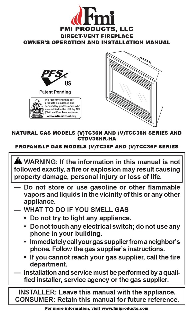
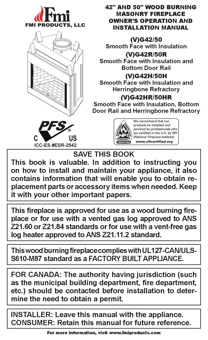
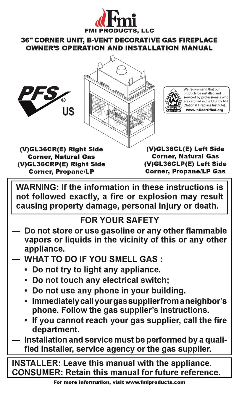
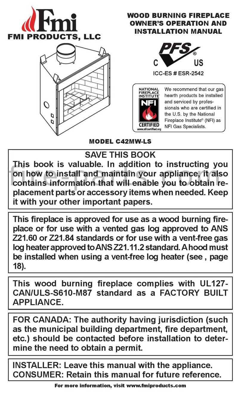
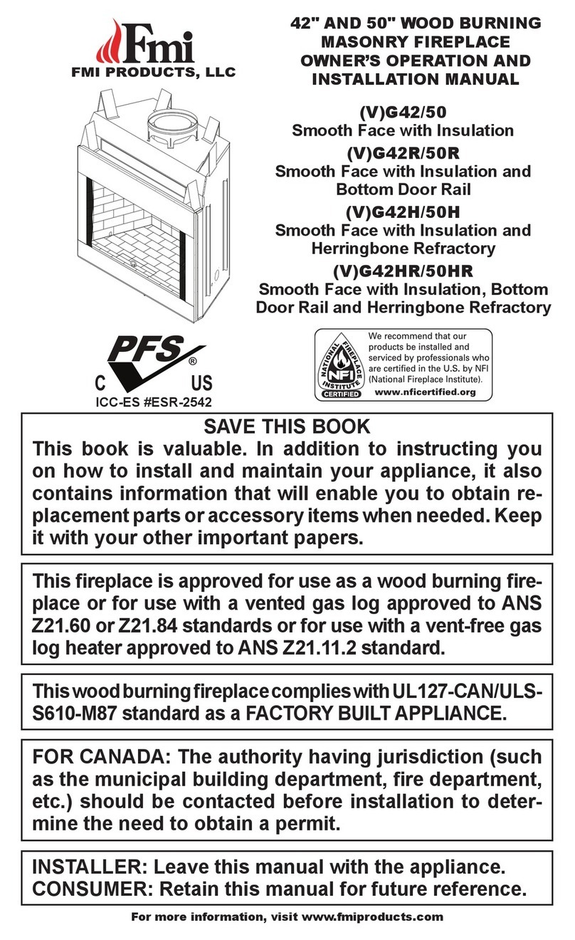
  9. FMI VLDV43NE Quick start guide

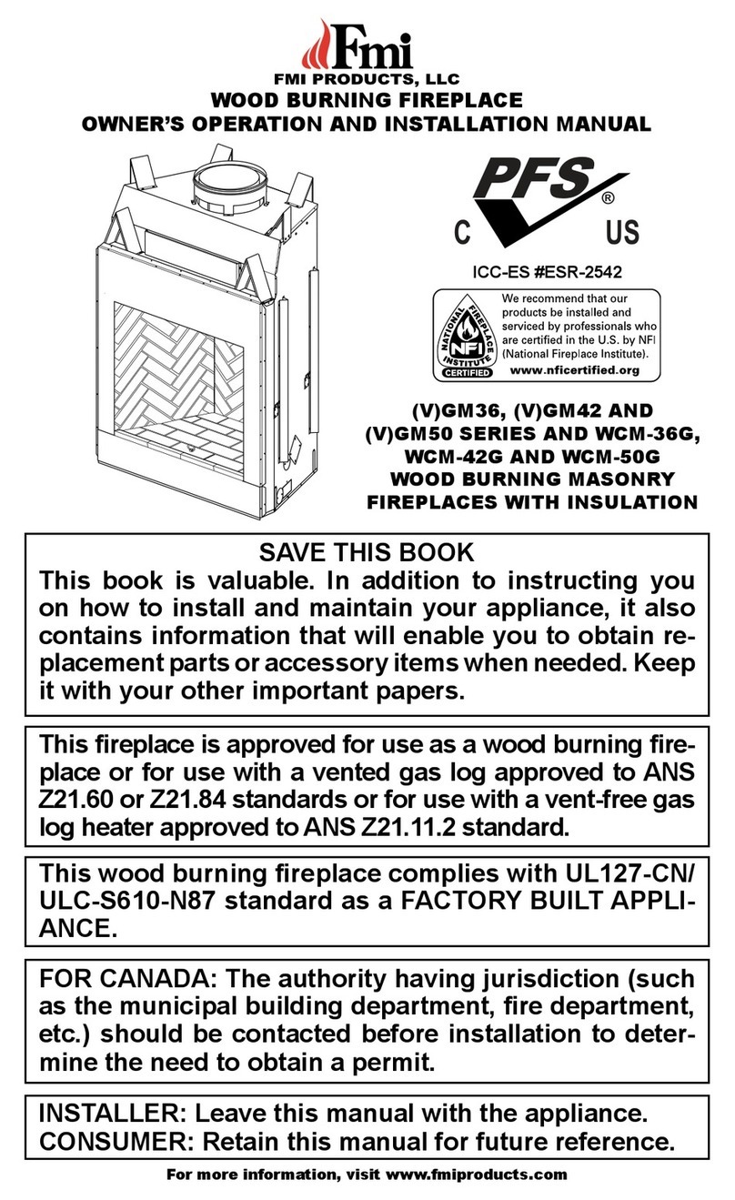
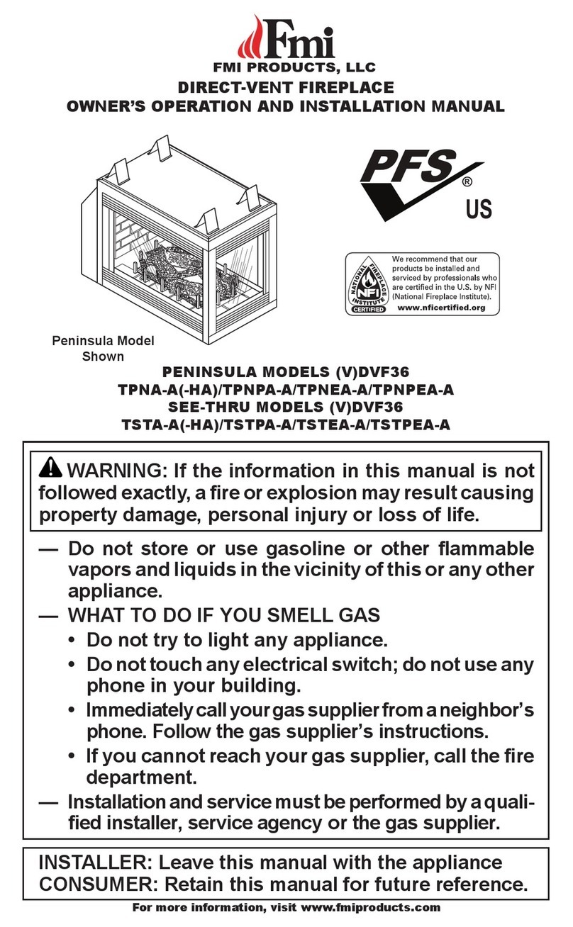
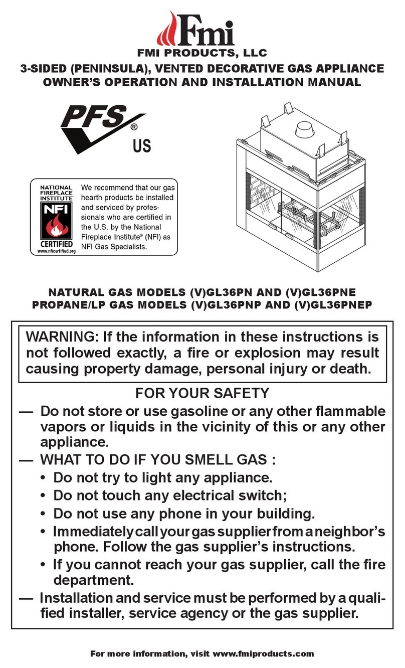
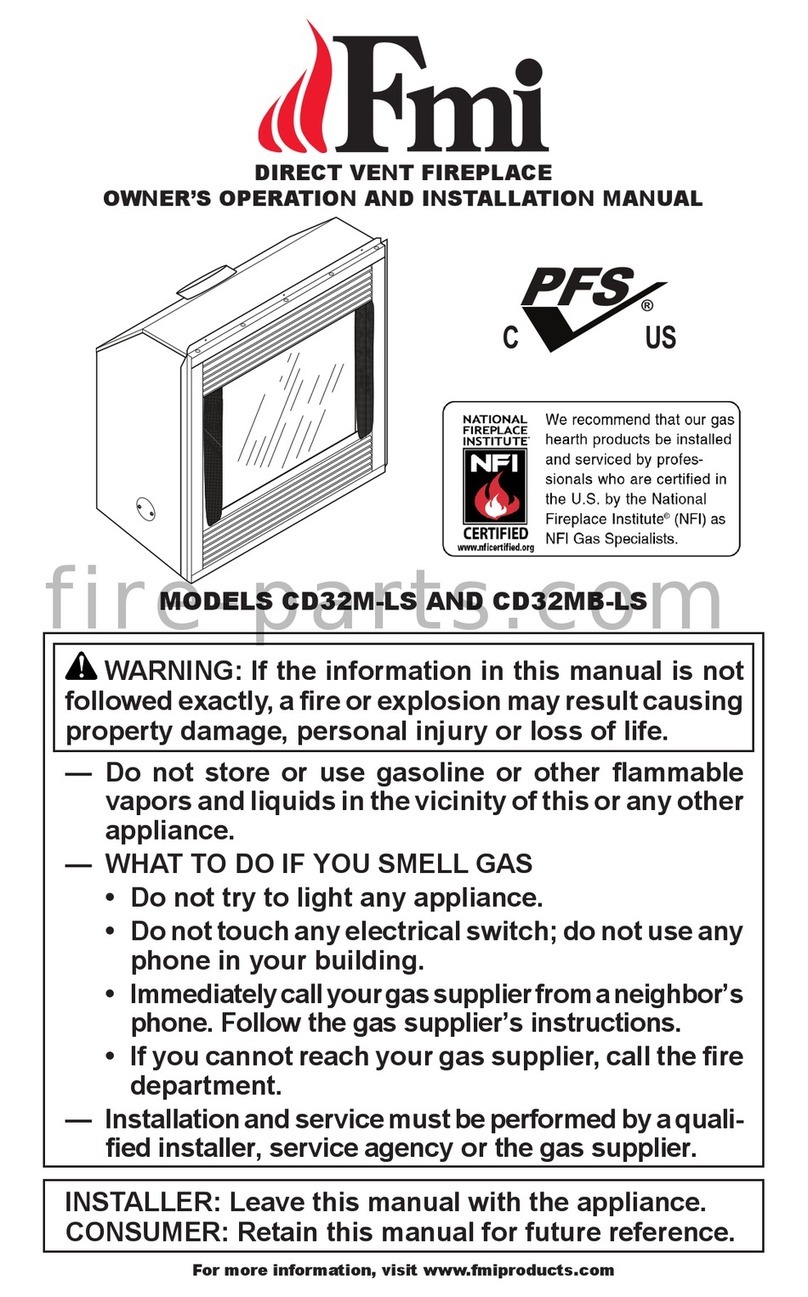
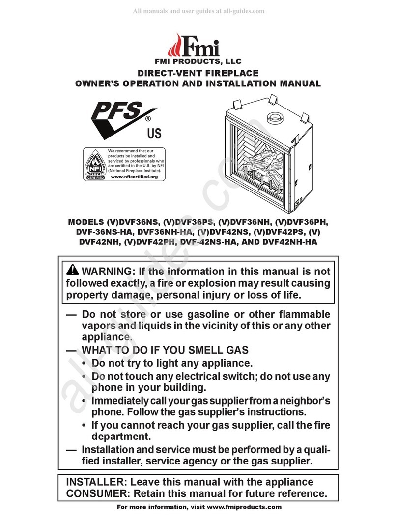
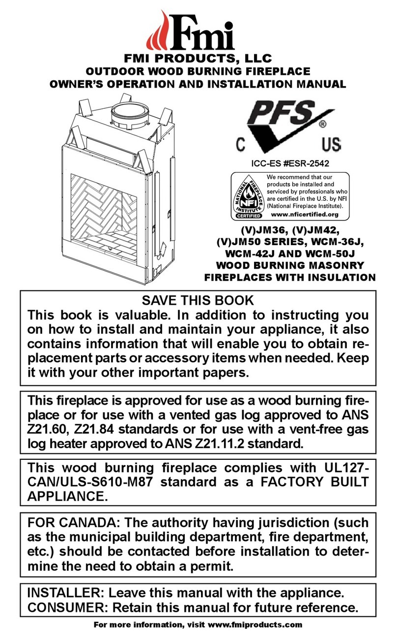
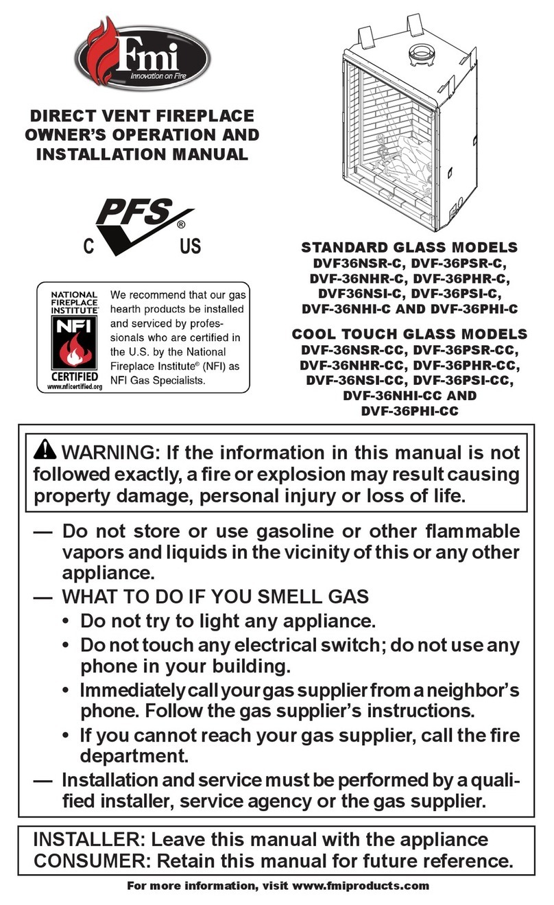
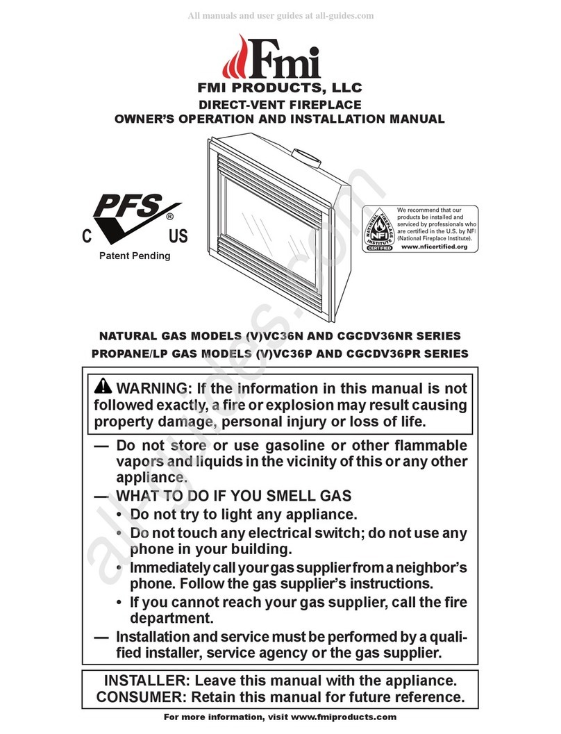
FMI VLDV43NE Quick start guide

For more information, visit www.fmiproducts.com
WARNING: If the information in this manual is not
— WHAT TO DO IF YOU SMELL GAS
-
DIRECT VENT
FIREPLACE
OWNER’S OPERATION AND
INSTALLATION MANUAL


MODELS (V)LDV43NE AND (V)LDV43PE
www.fmiproducts.com 125898-01D2
SAFETY
-
service or maintenance can
Refer to this manual for correct
additional information consult
State of Massachusetts: The
in the Commonwealth of Mas-
chemicals known to the State
of California to cause cancer or
-
-
-
TABLE OF CONTENTS
Safety .................................................................. 2
Local Codes......................................................... 4
........................................... 5
Product Features ................................................. 5
Requirements for the Commonwealth of
Massachusetts..................................................... 6
Pre-installation..................................................... 7
Location of Termination Cap.............................. 10
Venting Installation .............................................11
Fireplace Installation.......................................... 19
Operation........................................................... 26
Inspecting Burners............................................. 28
Cleaning and Maintenance................................ 28
Gas Control Module System.............................. 30
Troubleshooting................................................. 34
Wiring Diagram.................................................. 37
Parts .................................................................. 38
Accessories ....................................................... 41
.................................................... 42
Replacement Parts............................................ 42
Technical Service............................................... 42
Service Hints ..................................................... 42
Warranty ..............................................Back Cover
www.fmiproducts.com
125898-01D 3
-
-
FMI PRODUCTS, LLC vent pipe components
and terminations.
National Safety
Standards and is listed and tested by PFS Cor-
poration to ANSI Z21.88/CSA 2.33 standard as
in fresh air for combustion through the outer
pipe and combustion gases are exhausted
through the inner pipe. If the glass door assem-
bly and venting pipe are not properly seated,
connected and sealed, carbon monoxide leak-
Early signs of
with headaches, dizziness or nausea. If you
working properly. Have
-
fected by carbon monoxide than others. These
include pregnant women, people with heart
or lung disease or anemia, those under the
Natural and
propane/LP gas are odorless. An odor-making
agent is added to the gas. The odor helps you
detect a gas leak. However, the odor added to
the gas can fade. Gas may be present even
though no odor exists.
Make certain you read and understand all
warnings. Keep this manual for reference. It
is your guide to safe and proper operation of
-
WARNING: Do not use a
-
SAFETY
Continued
WARNING: Do not allow fans
-
-
adults away from hot surface
-
-
dren when they are in the room
www.fmiproducts.com 125898-01D4
structure. Locate propane/LP supply
problems, do not use propane/LP fuel tank
of less than 100 lb. capacity.
2. If you smell gas
use any phone in your building
a neighbor’s phone. Follow the gas sup-
plier's instructions
4. Turn fireplace off and let cool before
servicing, installing or repairing. Only a
-
service person.
5. You must keep control compartments,
burners and circulating air passages
clean. More frequent cleaning may be
needed due to excessive lint and dust
from carpeting, bedding material, etc.
Turn off the gas valve and pilot light before
SAFETY
Continued
6. Have venting system inspected annually
have venting system cleaned or repaired.
See Cleaning and Maintenance, page 28.
7. Do not use any solid fuels (wood, coal,
-
place nameplate.
8. This appliance, when installed, must be
electrically grounded in accordance with
local codes or, in the absence of local
codes, with the National Electrical Code,
ANSI/NFPA 70 or Canadian Electrical
Code, CSA C22.1.
exposed to or under water. Immediately
for replacement of the unit.
removed, cracked or broken.
11. Provide adequate clearances around air
openings.
LOCAL CODES
local codes. In the absence to local codes,
use the current National Fuel Gas Code ANSI
Z223.1/NFPA 54* CSA-
B149.1 Installation Code
*Available from:
American National Standards Institute, Inc.
1430 Broadway
New York, NY 10018
National Fire Protection Association, Inc.
Batterymarch Park
Quincy, MA 02269
www.fmiproducts.com
125898-01D 5
Figure 1 - Direct Vent Linear Fireplace
Glass Door
Pebble Pan
Flue Collar
Nailing
Flange
Access Door
To p
Spacers
PRODUCT IDENTIFICATION
PRODUCT FEATURES
These are a few facts that can help you un-
outside of your home in several ways. It
may vent to an outside/exterior wall (hori-
important to allow for proper operation.
You must follow the venting instructions
very carefully for either vertical or horizontal
applications.
of your house provided all local codes and
these installation instructions are followed.
may notice some amount of condensation
is normal and will disappear after 10-20
minutes of operation.
sealed gas operating unit. It requires ap-
proximately 10-20 minutes of operating
www.fmiproducts.com 125898-01D6
REQUIREMENTS FOR THE COMMONWEALTH OF
MASSACHUSETTS
For all side wall horizontally vented gas fueled
equipment installed in every dwelling, building or
structure used in whole or in part for residential
purposes, including those owned or operated by
the Commonwealth and where the side wall ex-
including but not limited to decks and porches,
INSTALLATION OF CARBON
MONOXIDE DETECTORS
At the time of installation of the side wall horizon-
tal vented gas fueled equipment, the installing
wired carbon monoxide detector with an alarm
where the gas equipment is to be installed. In
observe that a battery operated or hard wired car-
bon monoxide detector with an alarm is installed
on each additional level of the dwelling, building or
structure served by the side wall horizontal vented
gas fueled equipment. It shall be the responsibility
of the property owner to secure the services of
of hard wired carbon monoxide detectors.
In the event that the side wall horizontally
vented gas fueled equipment is installed
in a crawl space or an attic, the hard wired
carbon monoxide detector with alarm and
battery back-up may be installed on the next
In the event that the requirements of this
subdivision can not be met at the time of
completion of installation, the owner shall
operated carbon monoxide detector with an
alarm shall be installed.
Each carbon monoxide detector as required
in accordance with the above provisions shall
comply with NFPA 720 and be ANSI/UL 2034
SIGNAGE
permanently mounted to the exterior of the
above grade directly in line with the exhaust
vent terminal for the horizontally vented gas
fueled heating appliance or equipment. The
sign shall read, in print size no less than 1/2" in
size, "GAS VENT DIRECTLY BELOW. KEEP
CLEAR OF ALL OBSTRUCTIONS".
INSPECTION
The state or local gas inspector of the side
wall horizontally vented gas fueled equipment
shall not approve the installation unless, upon
inspection, the inspector observes carbon
monoxide detectors and signage installed in
accordance with the provisions of 248 CMR
EXEMPTIONS: The following equipment is
"Equipment Not Required To Be Vented"
in the most current edition of NFPA 54 as
vented gas fueled equipment installed in a
room or structure separate from the dwell-
ing, building or structure used in whole or
in part for residential purposes.
MANUFACTURER REQUIREMENTS
When the manufacturer of Product Approved
side wall horizontally vented gas equipment
provides a venting system design or venting
system components with the equipment, the
instructions provided by the manufacturer for
installation of the equipment and the venting
system shall include:
the venting system design or the venting
design or venting system.
Provided
When the manufacturer of a Product Ap-
proved side wall horizontally vented gas fu-
eled equipment does not provide the parts for
venting systems", the following requirements
The referenced "special venting system" in-
structions shall be included with the appliance
-
uct Approved by the Board, and the instruc-
tions for that system shall include a parts list
and detailed installation instructions.
A copy of all installation instructions for all
Product Approved side wall horizontally
vented gas fueled equipment, all venting in-
structions, all parts lists for venting instruc-
tions, and/or all venting design instructions
shall remain with the appliance or equipment
at the completion of the installation.
www.fmiproducts.com
125898-01D 7
PRE-INSTALLATION
LOCATION AND SPACE
REQUIREMENTS
-
that rafters and wall studs are not in the way
of the venting system. Choose a location
where the heat output is not affected by drafts,
air conditioning ducts, windows or doors.
Be aware of all restrictions and precautions
before deciding the exact location for your
follow these rules:
areas or near furniture or draperies.
carpeting, vinyl tile or any combustible mate-
rial other than wood, it must be installed on a
metal or wood panel extending the full width
directly against wall or framing material.
See framing details, page 8.
-
tant to observe the minimum clearances
shown in Figure 7, page 10.
or siding.
any obstruction such as
bushes, garden sheds, fences, decks or
utility buildings within 24" from the front of
the termination cap and the front of outside
air vent.
air vent where excessive snow or ice build
up may occur. Be sure to clear vent ter-
mination area after snow falls to prevent
accidental blockage of venting system.
When using snow blowers, do not direct
snow towards vent termination area.
CLEARANCES
Minimum clearances to combustibles for the
*Back and sides 1"
Perpendicular walls 8"
63"
Top of Enclosure
63"
Top of Standoffs 0"
Vent 1"
venting
with insulation or other materials.
-
-
FRAMING AND FINISHING
Figure 2, page 8 shows typical framing of this
see-thru installation. All minimum clearances
must be met. Vent pipe needs to maintain 1"
clearance. Steel framing may be necessary or
wood studs may be notched. Concrete board
shown in Figure 4, page 8.
If you are using a separate combustible man-
tel piece, refer to Figure 5 page 8 for proper
installation height. You can install noncombus-
Note: Noncombustible mantels may discolor!
www.fmiproducts.com 125898-01D8
PRE-INSTALLATION
Continued
Figure 2 - Framing Clearances for One
Sided Application
Figure 3 - Framing Clearances for See-
Thru Application






Figure 5 - Clearances for Combustible
Mantels
Mantel Mantel from
1 12" A 24"
2 9" B 21"
3 6" C 18"
4 4" D 16"
5 2" E 14"









Figure 4 - Installing Concrete Board
Concrete
Board


 
 
 





   

www.fmiproducts.com
125898-01D 9
 
  
  
   
 
  
 

 
 
 
 
 

 


 
 
 
 

 
PRE-INSTALLATION
Continued
Figure 6 - (V)LDV43 Series Dimensions
www.fmiproducts.com 125898-01D10

  


























        
 
        
    
          
             
         
          
         
 
      
      
  
         
         
        
         
       
       
         
        
  
          

         
        
             
         
          
         
 
          
            
    
          
       
      
    
          
         
        
      
                
      
                    
               
        
    
 




    
       
  
       
  
    
    
     
 
    
    
   


      
    


 

    
    
    



        

LOCATION OF TERMINATION CAP
Figure 7 - Minimum Clearances for Termination Cap
www.fmiproducts.com
125898-01D 11
VENTING INSTALLATION
NOTICE: Donot seal termination
INSTALLATION PRECAUTIONS
protection
or when on roof tops
walls and ceilings
The following actions will void the warranty
on your venting system:
component
manufactured or approved by FMI
PRODUCTS, LLC
these instructions
-
-
-
on the horizontal sections,
NOTICE: Read these instruc-
-
These models are tested and approved for
pipe components and terminations.
The venting system must terminate on the
outside of the structure and can not be at-
separate solid fuel or gas burning appliance.
A direct vent appliance must have its own
venting system. DO NOT common vent this
appliance.
These models are approved to be vented
either horizontally through an outside wall or
vertically through a roof or chase enclosure
using the following guidelines:
-
tally on an outside wall, you may install
a standoff if the termination cap is to be
such as vinyl, wood, stucco, etc.
cause excessive temperatures which could
-
bustibles are 1" on all sides except on the
horizontal sections, which requires 2" clear-
ance from the top of the pipe. Where the
termination cap penetrates a combustible
wall, 1" air space clearance is required.
-
nents on hand to help determine the exact
measurements when elbowing or offsetting.
-
ings or attic spaces.
4000 feet or greater, pay special attention
to venting requirement recommendations.
WARNING: Read all instruc-
Failure to do so could result in
NOTICE: Failure to follow these
www.fmiproducts.com 125898-01D12
INSTALLATION PLANNING
There are two basic types of direct vent
installation:
Horizontal Termination Installation
IMPORTANT: Horizontal square terminations
Horizontal installations using round termina-
-
termine the route your horizontal venting
venting has been installed. Some instal-
-
tions. Figures 11 and 12 on page 13 show
horizontal termination that will help you
decide which application best suits your
installation. Check to see if wall studs or
roof rafters are in the path of your desired
venting route. If they are, you may want
2. Direct vent pipe sections and components
are designed with special twist-lock con-
nections.
Twist-Lock Procedure: Female ends of
These lugs will slide straight into match-
Push pipe sections together and twist
one section clockwise approximately one-
quarter turn until sections are fully locked
Note: Horizontal runs of vent must be sup-
ported every three feet. Use wall straps
for this purpose.
3. Assemble desired combination of pipe
are long portions of venting run, pre-
assembled pipe sections may be installed
as subassemblies for convenience.
4. Carefully determine location where vent
pipe assembly will penetrate outside wall.
Center of hole should line up with center
line of horizontal vent pipe. Mark wall for
an 11 1/2" x 11 1/2" square hole. Cut and
frame square hole in exterior wall where
vent will be terminated. If wall being pen-
VENTING INSTALLATION
Continued
Figure 8 - Vent Pipe Connections
Female
Locking Lugs
Male
Slots
Figure 9 - Vent Opening Requirements
Center
of Hole
etrated is constructed of noncombustible
material, such as masonry block or con-
crete, a 8 1/2" hole with zero clearance is
WARNING: Do not recess











  













 
 
 
www.fmiproducts.com
125898-01D 13
VENTING INSTALLATION
Continued
5. Position
horizontal vent cap in center of the 8 1/2"
round hole and attach to exterior wall
with four wood screws provided. Before
attaching vent cap to exterior wall, run a
bead of non-hardening mastic (pliable
seal between it and outside wall.
Note: Four wood screws provided should
be replaced with appropriate fasteners for
stucco, brick, concrete or other types of
sidings (see Figure 10).
For vinyl
siding, stucco or wood exteriors, a siding
standoff may be installed between vent
cap and exterior wall. Siding standoff
prevents excessive heat from damaging
siding materials. Siding material must be
cut to accommodate standoff. Bolt vent
cap to standoff. Apply non-hardening
mastic around outside edge of standoff.
Position standoff/cap assembly in the
center of 11 1/2" square hole and attach to
exterior wall with provided wood screws
6.
pipe before connecting horizontal run to
Figure 10 - Installing Horizontal Vent Cap
(Noncombustible Exterior)
Wood
Screw
Vent Cap
Figure 11 - Installing Siding Standoff
(Combustible Exterior Wall)
Cut Siding Away to
Fit Standoff
Wood
Screw
Screws
Standoff
Vent
Cap
Apply Mastic
to All Four Sides
Vent Cap
(Horizontal
Interior Wall
Surface
Wall
Firestop
Horizontal
Vent Pipe
Figure 12 - Connecting Vent Cap with
Horizontal Vent Pipe
Screw
Apply
Mastic to All
Four Sides
-
sembly attached, toward wall and insert
vent pipe into horizontal termination. Pipe
overlap should be a minimum of 1 1/4" (see
surface and attach with screws provided.
See Figure 13, page 14, for horizontal
termination details.
noncombustible material if needed. Nail or
unit in place. IMPORTANT: -
is not level it will not work properly.
www.fmiproducts.com 125898-01D14
VENTING INSTALLATION
Continued
Figure 13 - Typical Horizontal
Termination Cap Mounting with
Additional Siding Standoff Installed
Siding
Standoff
Screws
High Wind
Termination
Apply
Mastic to
Outside
Edge of
Standoff
Exterior Wall with Vinyl Siding
11 1/2" x 11 1/2"
Framed Opening
Maintain 1"
Minimum Air
Space Around
Outer Pipe When
Penetrating a Wall
Minimum
Pipe
Overlap
11/4
Wall
Firestop
Direct
Vent
Pipe
-
rations for venting with horizontal termination
with a chart of critical minimum and maximum
dimensions which MUST be met.
NOTICE: Donot seal termination
WARNING: Never run vent
downward as this may cause
-
www.fmiproducts.com
125898-01D 15
VENTING INSTALLATION
Continued
GROUND FLOOR INSTALLATION
Recommended Applications:
square termination
Figure 14 - Horizontal Termination Using One 90° Elbow
Figure 15 - Horizontal Termination Using Two 90° Elbows
Wall
Firestop
90° Elbow
V + 90· Elbow
Horizontal High
Wind Square
Termination
1' Pipe Min. On
Horizontal Run
53'' Min.
Plus ¼''
Rise per
Foot
Minimum Maximum
53" 1 ft. 7 ft.
65" 2 ft. 11 ft.
77" 3 ft. 20 ft.
V + H = 40 feet maximum
H = 20 feet maximum
Horizontal
(H + H
5' Min. 8' Max
6' Min. 10' Max
7' Min. 15' Max
20' Min. 20' Max
www.fmiproducts.com 125898-01D16
VENTING INSTALLATION
Continued
Figure 16 - Offset with Wall Strap and 45°
Elbows
45° Elbow
Wall Strap
Roof Flashing
Ceiling Firestop
Installation
Note: Vertical restrictor must be installed in
all vertical installations.
1. Determine route your vertical venting
other framing will obstruct venting system,
cutting load bearing members. Note: Pay
special attention to these installation
instructions for required clearances (air
space) to combustibles when passing
through ceilings, walls, roofs, enclosures,
attic rafters, etc. Do not pack air spaces
with insulation. Also note maximum
vertical rise of venting system and any
maximum horizontal offset limitations.
plumb line down from ceiling to position
where vent will penetrate ceiling. Drill a
small locating hole at this point.
3. Drop a plumb line from inside of roof to
locating hole in ceiling. Mark center point
where vent will penetrate roof. Drill a small
locating hole at this point.
Roof Pitch
Flat to 6/12 1
6/12 to 7/12 1.25
Over 7/12 to 8/12 1.5
Over 8/12 to 9/12 2
Over 9/12 to 10/12 2.5
Over 10/12 to 11/12 3.25
Over 11/12 to 12/12 4
Over 12/12 to 14/12 5
Over 14/12 to 16/12 6
Over 16/12 to 18/12 7
Over 18/12 to 20/12 7.5
Over 20/12 to 21/12 8.0
1. Cut a 11 1/2" square hole in ceiling using
locating hole as a center point. Opening
should be framed to 11 1/2" x 11 1/2" inside
dimensions, as shown in Figure 9 on page
12 using framing lumber the same size as
from top side. This prevents loose insula-
tion from falling into required clearance
space. If area above ceiling is a living
Firestop should be installed with no less
Figure 17 - Installing Firestop
If area above is a living space, install
If area above is an attic or insulated area,
www.fmiproducts.com
125898-01D 17
VENTING INSTALLATION
Continued
2. Assemble desired lengths of pipe and
and elbow connections are fully twist-
3. Cut a hole in the roof using locating hole
as a center point. (Cover any exposed
open vent pipes before cutting hole in
1/2" x 11 1/2" hole must be
may be larger depending on pitch of roof.
There must be a 1" clearance from vent
pipe to combustible materials. Frame
opening as shown in Figure 9 page 12.
4. Connect a section of pipe and extend up
through hole.
Note: If an offset is needed to avoid
obstructions, you must support vent pipe
every 3 feet. Use wall straps for this pur-
pose (see Figure 14, page 15). Whenever
possible, use 45° elbows instead of 90°
elbows. The 45° elbow offers less restric-
-
tending through roof. Secure base of
16. There must be a 1" clearance from
vent pipe to combustible materials.
6. Continue to add pipe sections until height
of vent cap meets the minimum building
code requirements described in Figure 7
on page 10.
Note: You must increase vent height for
steep roof pitches. Nearby trees, adjoining
similar factors may cause poor draft or
down-drafting in high winds. Increasing
vent height may solve this problem.
7. Twist-lock vent cap onto last section of
vent pipe.
Note: If vent pipe passes through any occupied
and closets, you must enclose pipe. You may
frame and sheetrock enclosure with standard
construction material. Make sure and meet the
minimum allowable clearances to combustibles.
Figure 17 and 18, page 17 and 18, shows the
Figure 18 - Vertical Venting
Note: Vertical (V1 2
V + H = 40' Max.
H=20' Max.
Horizontal
5' Min. 10' Max
6' Min. 14' Max
7' Min. 20' Max
20' Max. 20' Max
Note: Install a
VR-58 vertical
restrictor ring
into inner pipe
section prior to
attaching vent
termination cap.
90°
Elbow
www.fmiproducts.com 125898-01D18
AND COMPONENTS
P58-6 6" Section Double Wall Pipe,
Galvanized
P58-12 12" Section Double Wall Pipe,
Galvanized
P58-24 24" Section Double Wall Pipe,
Galvanized
P58-36 36" Section Double Wall Pipe,
Galvanized
P58-48 48" Section Double Wall Pipe,
Galvanized
Double Wall Pipe, Galvanized
E58-45 45° Elbow, Galvanized
E58-90 90° Elbow, Galvanized
HTS-58 Horizontal Square
Termination, Galvanized
HHT-58 High Wind Round
Termination, Galvanized
VT-58 Vertical Round Termination,
Galvanized
SC-58 Storm Collar, Galvanized
WF-58 Wall Firestop, Galvanized
RF-58-6 Roof Flashing - 0 to 6/12
Pitch, Galvanized
RF-58-12 Roof Flashing - 6/12 to 12/12
Pitch, Galvanized
VR-58 Vertical Restrictor, Galvanized
S-58 Vinyl Siding Standoff,
Galvanized
WS-58 Wall Strap
CS-58 Cathedral Ceiling Support
FP-58 Firestop Plate
SF-58 Stucco Flashing - For use
with HTS-58
RF-58 Flat Roof Flashing
PF58-957 Flex Vent 9" - 27"
PF58-1236 Flex Vent 12" - 36"
PF58-1854 Flex Vent 18" - 54"
VENTING INSTALLATION
Continued
V = 40' max.
HIGH ALTITUDE INSTALLATION
has been tested and approved in the USA for
-
you may need to decrease the input rating
smaller size. Reduce input 4% for each 1000
your local gas company for proper derate
authorities.
For assistance with any high altitude
installation call FMI PRODUCTS, LLC at
1-866-328-4537.
www.fmiproducts.com
125898-01D 19
FIREPLACE INSTALLATION
according to your gas type.
INSTALLING GAS PIPING TO
FIREPLACE LOCATION
-
WARNING: For natural
Installation Items Needed
have the items listed below.
-
* An equipment shutoff valve with 1/8" NPT
tap is an acceptable alternative to test gauge
connection. Purchase the equipment shutoff
valve from your retailer.
For propane/LP connection only, the installer
must supply an external regulator. The exter-
nal regulator will reduce incoming gas pres-
sure. You must reduce incoming gas pressure
to between 11" and 14" of w.c. pressure. If
you do not reduce incoming gas pressure,
external regulator with the vent pointing down
as shown in Figure 19. Pointing the vent down
protects it from freezing rain or sleet.
CAUTION: Use only new,
-
Installation must include an equipment shutoff
valve, union and plugged 1/8" NPT tap. Locate
NPT tap within reach for test gauge hook up.
IMPORTANT: Install main gas valve (equip-
The main gas valve is for turning on or shutting
off the gas to the appliance.
Figure 20 - External Regulator with Vent
Pointing Down (Propane/LP Only)
Propane/LP
Supply Tank
External Regulator
with Vent Pointing
Down
www.fmiproducts.com 125898-01D20
Check your building codes for any special
requirements for locating equipment shutoff
threads. This will prevent excess sealant from
going into pipe. Excess sealant in pipe could
FIREPLACE INSTALLATION
Continued
Figure 21 - Gas Connection
Equipment Shutoff Valve
with 1/8" NPT Tap*
3" Minimum
Approved
Flexible
Gas Line
Cap Pipe Tee
Joint Nipple
Sediment Trap/
Drip Leg
Natural - From
Gas Meter (5.5"
W.C. to 10.5" W.C.
From
External Regulator
(11" W.C. to 14"
* The equipment shutoff valve may be sup-
plied with the appliance or you can purchase
it from your retailer.
Figure 22 - Connecting Incoming Gas Line to Flex Gas Line
We recommend that you install a sediment
trap/drip leg in supply line as shown in Figure
21. Locate sediment trap/drip leg where it
is within reach for cleaning. Install in piping
Locate sediment trap/drip leg where trapped
matter is not likely to freeze. A sediment trap
traps moisture and contaminants. This keeps
sediment trap/drip leg is not installed or is in-
CONNECTING FIREPLACE TO GAS
SUPPLY
Installation Items Needed
-
through one of the access holes on side
3. Check all gas connections for leaks. See
Checking Gas Connections, page 21.
Note:
shown for clarity
Tapping




 
Inlet Pressure Tap
Outlet Pressure Tap
Gas Shutoff
Valve
Flexible
Gas Line
Do NOT
Kink
1/2" NPT
Incoming
Gas Line
Set Screw

Other manuals for VLDV43NE

1

This manual suits for next models

3

Other FMI Indoor Fireplace manuals

FMI CD36RN User manual

FMI

FMI CD36RN User manual

FMI VB36 Quick start guide

FMI

FMI VB36 Quick start guide

FMI MMST43 User manual

FMI

FMI MMST43 User manual

FMI Vs68ST Quick start guide

FMI

FMI Vs68ST Quick start guide

FMI VCD36RN Quick start guide

FMI

FMI VCD36RN Quick start guide

FMI DVF34 Quick start guide

FMI

FMI DVF34 Quick start guide

FMI LVF43NR Quick start guide

FMI

FMI LVF43NR Quick start guide

FMI (V)VC42NE series Quick start guide

FMI

FMI (V)VC42NE series Quick start guide

FMI B36I Quick start guide

FMI

FMI B36I Quick start guide

FMI (V)KC42NE series Quick start guide

FMI

FMI (V)KC42NE series Quick start guide

FMI VUM Series Quick start guide

FMI

FMI VUM Series Quick start guide

FMI P325E(B) Specification sheet

FMI

FMI P325E(B) Specification sheet

FMI (V)3612ST Safety guide

FMI

FMI (V)3612ST Safety guide

FMI EADV36NE Quick start guide

FMI

FMI EADV36NE Quick start guide

FMI T32N-A Quick start guide

FMI

FMI T32N-A Quick start guide

FMI (V)BFBF36 series Quick start guide

FMI

FMI (V)BFBF36 series Quick start guide

FMI DVFH34 Quick start guide

FMI

FMI DVFH34 Quick start guide

FMI DVC36B Quick start guide

FMI

FMI DVC36B Quick start guide

FMI (V)DVF36NS Quick start guide

FMI

FMI (V)DVF36NS Quick start guide

FMI VCD36RN Quick start guide

FMI

FMI VCD36RN Quick start guide

FMI CGMFN Safety guide

FMI

FMI CGMFN Safety guide

FMI VLDV43NE Specification sheet

FMI

FMI VLDV43NE Specification sheet

FMI (V)GL36CR(E) Quick start guide

FMI

FMI (V)GL36CR(E) Quick start guide
FMI S36 Series User manual

FMI

FMI S36 Series User manual

Popular Indoor Fireplace manuals by other brands

Ecoflam MULTIFLAM 300.1 PR manual

Ecoflam

Ecoflam MULTIFLAM 300.1 PR manual

Regency Z2510L Owners & installation manual

Regency

Regency Z2510L Owners & installation manual

Warmington Debonaire DUPLO 1200 installation instructions

Warmington

Warmington Debonaire DUPLO 1200 installation instructions

Hearth and Home Technologies BE-32 owner's manual

Hearth and Home Technologies

Hearth and Home Technologies BE-32 owner's manual

Marco Traditional A41MTR Installing & operating manual

Marco

Marco Traditional A41MTR Installing & operating manual

Imperial Fires TF4 Installation and maintenance instructions

Imperial Fires

Imperial Fires TF4 Installation and maintenance instructions

Lacunza AUSTRALIA Verona 1000 Instruction book

Lacunza

Lacunza AUSTRALIA Verona 1000 Instruction book

Sierra Flame NEWCOMB-36 Installation and operating instructions

Sierra Flame

Sierra Flame NEWCOMB-36 Installation and operating instructions

Travis Industries 564 DF GSR2 owner's manual

Travis Industries

Travis Industries 564 DF GSR2 owner's manual

Enviro 828 DV.FS. owner's manual

Enviro

Enviro 828 DV.FS. owner's manual

Lennox Hearth Products LEGACY C260 Installation and operation manual

Lennox Hearth Products

Lennox Hearth Products LEGACY C260 Installation and operation manual

Continental Refrigerator CBLP Series owner's manual

Continental Refrigerator

Continental Refrigerator CBLP Series owner's manual

Jøtul F 602 installation manual

Jøtul

Jøtul F 602 installation manual

Quadra-Fire 21M-ACC owner's manual

Quadra-Fire

Quadra-Fire 21M-ACC owner's manual

Global G20 installation manual

Global

Global G20 installation manual

Osburn 1800 owner's manual

Osburn

Osburn 1800 owner's manual

Superior BC36MH installation instructions

Superior

Superior BC36MH installation instructions

Montigo L38DF series Installation & maintenance manual

Montigo

Montigo L38DF series Installation & maintenance manual

manuals.online logo
manuals.online logoBrands
  • About & Mission
  • Contact us
  • Privacy Policy
  • Terms and Conditions

Copyright 2025 Manuals.Online. All Rights Reserved.