FMS CMGZ411 User manual

Operating Manual CMGZ411/421
Digital microprocessor controlled tension control unit
V2.01 05/04 sd
This operation manual is also available in German.
Please contact your local representative.
Diese Bedienungsanleitung ist auch in Deutsch erhältlich.
Bitte kontaktieren Sie die Vertretung im zuständigen Land.
© by FMS Force Measuring Systems AG, CH-8154 Oberglatt – All rights reserved.

Operating Manual CMGZ411/421
2
1Safety Instructions
Danger
Some contacts of the 230VAC version are under 230V tension! Mortal danger! Disconnect power
supply before open the housing!
Danger
The tension controller can operate drives or brakes with high performance. It has no built-in
emergency stop function. Switching off the power supply is not sufficient to prevent personal
injury or mechanical damage! To provide safety of man and machine in case of malfunction, the
person responsible for system design has to establish specific safety procedures such as emergency
stop circuits, etc.
Caution
Bad earth connection may cause electric shock to persons, malfunction of the total system or damage
of the electronic unit! It is vital to ensure that proper earth connection is done.
Caution
The processor board is mounted directly behind the operation panel. Improper handling may damage
the fragile electronic equipment! Don’t use rough tools as screwdrivers or pliers! Don’t touch
processor board! Touch earthed metal part to discharge static electricity before removing operation
panel!
Caution
Proper function of the web tension controller is only guaranteed with the recommended application
of the components. In case of other arrangement, heavy malfunction can be the result. Therefore, the
installation instructions on the following pages must be followed strictly.
Caution
Local installation regulations are to preserve safety of electric equipment. They are not taken into
consideration by this operating manual. However, they have to be followed strictly.

Operating Manual CMGZ411/421
3
2Table of contents
1Safety Instructions ............................................................................................ 2
2Table of contents................................................................................................ 3
3Description......................................................................................................... 4
3.1 Common....................................................................................................................................4
3.2 Special functions CMGZ411.....................................................................................................4
Special functions CMGZ421.................................................................................................................4
3.3 Block Diagram CMGZ411........................................................................................................5
3.4 Block Diagram CMGZ421........................................................................................................5
4Controller theory............................................................................................... 6
5The 4 quadrants in drive technology............................................................... 7
6Quick installation guide.................................................................................... 7
7Applications ....................................................................................................... 8
7.1 Table of the application versions ..............................................................................................8
7.2 Determination of the machine configuration ............................................................................9
8Wiring............................................................................................................... 14
8.1 Wiring diagram of the web tension controller CMGZ411......................................................14
8.2 Wiring diagram of the web tension controller CMGZ421......................................................15
8.3 Wiring diagram CMGZ411.E / CMGZ421.E .........................................................................15
9Initial operation of measuring amplifier.......................................................17
9.1 Initial operation of measuring amplifier CMGZ411...............................................................17
9.2 Initial operation of measuring amplifier CMGZ421...............................................................18
9.3 Correction input (CMGZ411).................................................................................................19
10 Initial operation of PID controller................................................................. 20
10.1 Parametrization of the PID controller .....................................................................................20
10.2 Determination of PID control parameters...............................................................................20
10.3 Enable controller.....................................................................................................................21
10.4 Controller lock ........................................................................................................................21
10.5 Setting of tension reference.....................................................................................................22
10.6 Time flow of the signals using a control loop with drive........................................................22
11 Serial interface (RS232)..................................................................................22
11.1 Wiring diagram of the RS232 interface ..................................................................................23
11.2 Command list..........................................................................................................................23
11.3 Write parameters.....................................................................................................................24
11.4 Read parameters......................................................................................................................25
12 Parametrization............................................................................................... 27
12.1 Parameter list CMGZ411........................................................................................................27
12.2 Parameter list CMGZ421........................................................................................................28
12.3 Description of the parameters .................................................................................................29
13 Trouble shooting..............................................................................................39
13.1 Trouble shooting CMGZ411...................................................................................................39
13.2 Trouble shooting CMGZ421...................................................................................................39
14 Technical Data.................................................................................................40

Operating Manual CMGZ411/421
4
3Description
3.1 Common
The CMGZ411/421 is a digital web tension controller. The electronic unit contains a microprocessor to handle all
calculations and communications, the highly accurate sensor power supply and the signal amplifier for the measuring
value. As operation interface it provides 4 keys, 4 LED’s and a 2x16 characters display in the front of the electronic
unit. All inputs are saved in an EEPROM. The electronic unit has no jumpers or trimmers to keep most accurate long-
time and temperature stability. There can be connected one or two force sensors to the electronic unit.
Strain gauge amplifier: The strain gauge amplifier provides the highly accurate 4V power supply. A highly accurate,
fixed difference amplifier rises the mV signal up to 10V. This signal will be fed to the A/D converter. The
microprocessor then does all application-specific calculations with the digitized measuring value (such as offset, gain,
low-pass filter). The tension feedback signal is available at the 0...10V analogue output.
Controller: The control unit compares the reference value with the measured feedback value and transmits the error to
the controller configurable as PI, PD or PID. The controller calculates the output signal according to the difference. The
output signal is provided as an analogue signal (0...10V / ±10V / 0...20mA / 4...20mA).
Interface: As standard, the electronic unit supports an RS232 interface. As an option, there is an additional board with
CAN-Bus interface available.
3.2 Special functions CMGZ411
Gain switching: For applications with different wrap angles, the gain factor can be changed easily using a digital input.
Correction input: For applications with continuously varying wrap angles (i.e. at winders/unwinders directly), the
CMGZ411 provides a 0..10V input for the continuous correction. The correction signal usually is obtained from a PLC
or from a potmeter that is mounted at the moving section of the machine. Correction can be set to linear or cosine
function.
Diameter calculation: In winder / unwinder applications, the controller is able to calculate the actual diameter.
Therefore it is necessary to get line speed information from a tacho roller or from a PLC. Line speed information is
given to the controller using a 10V input.
Taper function: Based on the diameter calculation, the CMGZ411 is able to reduce tension reference automatically
across the increasing diameter. Three different reduction curves (square, linear, square root) are available. The tension
then is reduced from given reference at center diameter to the desired reduction at the maximum winding diameter.
Note:
Only one of the features that use an analog input (Diameter, Correction input, analog reference) can be used at a time.
Special functions CMGZ421
Double channel measurment: The CMGZ421 calculates the tension reference values independently for the 2 bearings
of a measuring roller. Analogue outputs provide the feedback signals for channel A, channel B and channel A+B. The
controller uses the feedback signal A+B.
If the Difference between A and B exceeds a limit value, an error message occurs.
Gain switching: For applications with different wrap angles, the gain factor can be changed easily using a digital input.

Operating Manual CMGZ411/421
5
3.3 Block Diagram CMGZ411
C411000e
3.4 Block Diagram CMGZ421
C421000e

Operating Manual CMGZ411/421
6
4Controller theory
Web tension control loops
When manufacturing and processing foils, wires, ropes, paper and fabric sheets, it is important that the product is under
constant tension when guided over the cylinders. Tension may change when humidity, temperature, winding or
unwinding diameters vary or when the material is being printed, coated, glued or pressed.
Tension is measured constantly and maintained at the correct value with the FMS force measuring and control system.
The system includes the following components:
- Force measuring bearings or Force measuring rollers for mechanical / electrical conversion of the force
- Amplifier providing the excitation and the amplifier for the mV signal of the sensors (integrated in CMGZ411).
- Control unit for the comparison of tension reference and feedback value and the PID controller.
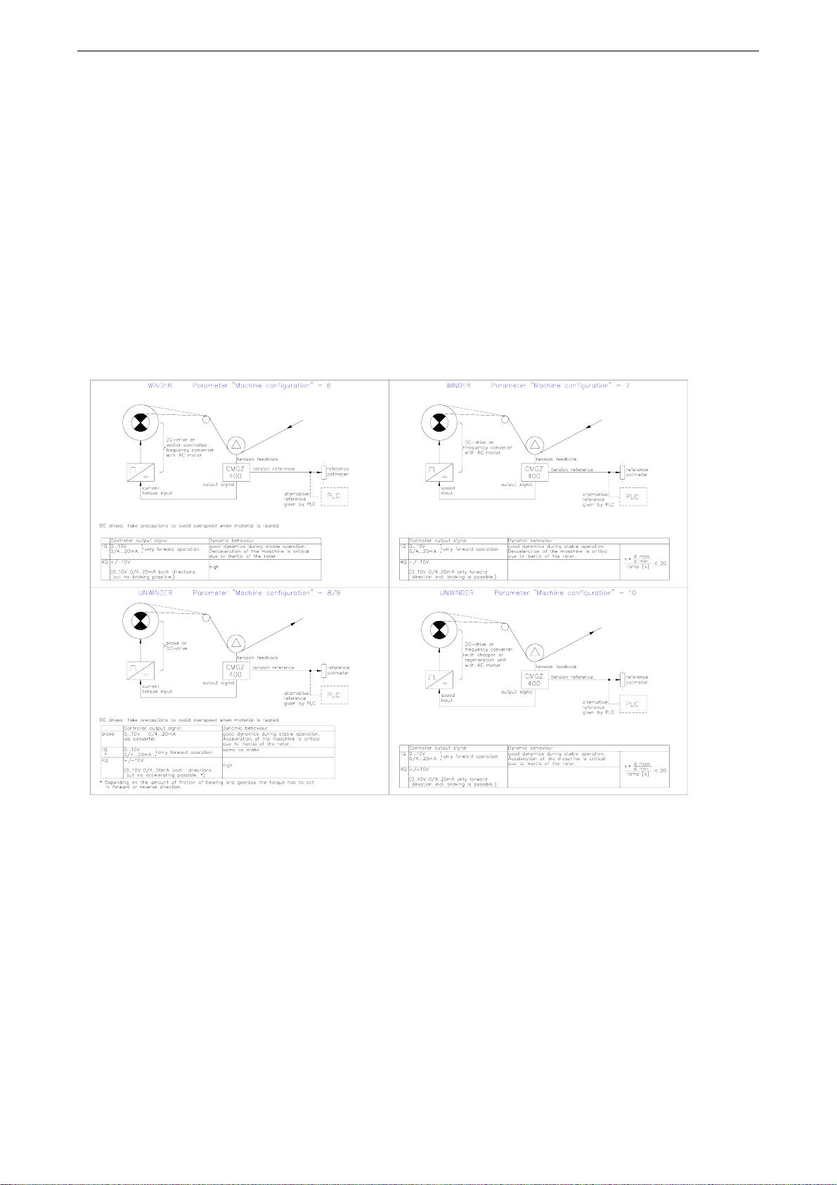
The output of the tension control unit drives either an electrical brake or a pneumatic brake via an electric/pneumatic
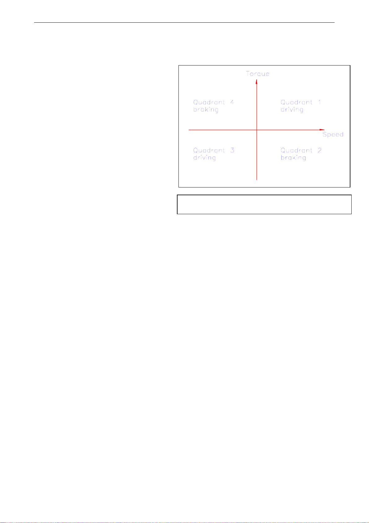
converter or an electric drive as a 1-quadrant or 4-quadrant model version. With a 4-quadrant electric drive, the tension
control unit is able to hold constant tension in both rotational directions as well as at standstill. As a tension control
loop prevents waste and tear of the band, this is a very economical solution for any kind of band material. The version
with compact steel housing (CMGZ411.E/421.E) allows to build a control system easily.
Control Unit
The function of any control loop is to maintain the feedback value exactly at the level of the reference and to minimize
the influence of any interference on the control loop.
In addition, the control loop must be stable under all operating conditions. These aims can only be achieved if the
dynamic behaviour of the control loop is adapted to the machine.
P Component
A controller with only a proportional component emits an output
signal that is proportional to the error. If the error equals to zero, the
output signal also equals to zero. A small error only can create a
small output signal which is not high enough to compensate the
complete error. That means that a controller with only a proportional
component will have a steady error depending on the p factor. The
characteristic value for a P controller is the proportional factor Xp.
I Component
A controller with an integral component integrates the error signal
continuously and emits the result as an output signal. The I controller
adds also very small differences between reference and feedback to
the output signal and thus, the output is adjusted until the error equals to zero. This output value is maintained until a
new error occurs. The integral component therefore allows zero error in steady state. The characteristic value for an I-
controller is the time Tn.
D Component
A controller with derivative component emits an output signal corresponding to the differentiated error signal.
Therefore, the value of this signal is proportional to the changing speed of the error signal. If the feedback value
deviates from the reference, the derivative component increases much faster than the proportional component. The
controller is able to react when even a small error occures, because it reacts already to a slightly changing error signal.
The characteristic value for a D controller is the time Tv.
Advantages of digital controllers compared with analog controllers
Digital controllers have exactly reproducible behaviour, because every parameter is known as an exact number. They
thus have very good long-term and temperature stability. This feature also allows one to interchange two units without
readjustments at the unit.
The initial adjustment usually is much easier, because numerical values are entered and no potentiometers have to be
turned a few degrees.
Digital units usually have a standard interface to a PLC, personal computer or other equipment. That makes it very easy
to integrate them into complex control systems. This concept simplifies initial operation and maintenance and allows
easy changement of some parameters when the processed goods are changing, etc.
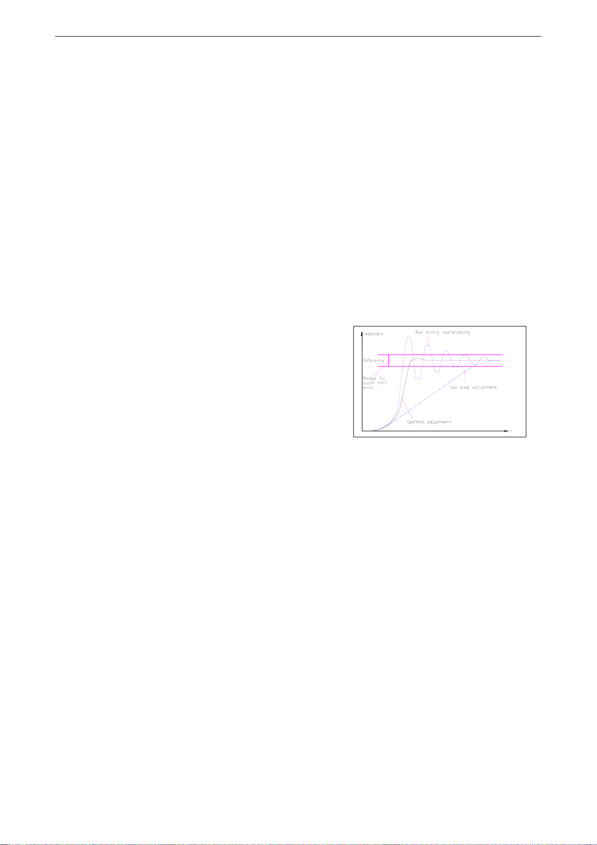
Diagram:Step response of a PID
controller

Operating Manual CMGZ411/421
7
5The 4 quadrants in drive technology
The four quadrants in drive technology refer to the
speed/torque diagram shown. The x axis shows
speed and the y axis shows torque.
The first quadrant shows positive speed and positive
torque and this results in positive power, eg. drive in
positive direction. In the second and fourth
quadrants, the power is negative because the signs
of speed and torque are different. In the third
quadrant, torque and speed are negative and this
results in positive power, which means driving in
negative direction.
A brake can work only in the second or the fourth
quadrant, because it is not able to drive by
definition. A 1-quadrant drive usually works in the
first quadrant, but can be installed to work in the
third quadrant also. It is not possible to brake with a
1-quadrant drive. A four-quadrant drive is able to
work in all 4 quadrants and able to drive and to
brake in positive and negative rotational direction.
Application
In applications where you need only low dynamic
response, it is possible to use 1-quadrant drives. If a
machine not only has to accelerate fast but also has to decelerate fast, it is necessary to use a 4-quadrant drive to switch
from driving to braking immediately. Only a 4-quadrant drive is able to handle both processes.
A brake would be able to help in the deceleration process, but in the acceleration phase, the brake for itself is
insufficient.
6Quick installation guide
•Find your application on pages 8-13
•Check all your requirements such as:
tension reduction / gain switching / analog outputs / line speed input
•draw your wiring diagram according to the wiring diagrams on pages 14-16. Do not forget the digital input
„controller enabled“!
•connect your components
•Parametrize: nominal force / Machine configuration (according to your chosen number) /
output configuration / start speed / start limit / synchronisation stop
•Put system into operation and adjust the PID controller as described on pages 20-22
•If needed, do additional adjustments (such as tension reduction, gain switching, scaling and filtering of analogue
outputs, etc.)
POWER = TORQUE x REVOLUTION SPEED

Operating Manual CMGZ411/421
8
7Applications
7.1 Table of the application versions
With the table and the following principle images, the machine configuration is determined.
snoitairavrellortnoC snoitacilppA
redniW redniwnU evirdetaidemretni
golanA noisnet ecnerefer
repaT noitcnuf dna retemaid noitaluclac
deepseniL dnatupni retemaid no
italuclac
euqroT dellortnoc
evirDCD• rotcev• dellortnoc evirD
deepS
dellortnoc
evirDCD• ycneuqerfCA• retrevnoc
euqroT dellortnoc
evirDCD• ekarB•
deepS
dellortnoc
evirDCD• ycneuqerfCA(• htiwretrevnoc )tinuekarB
euqroT dellortnoc
evirDCD• ycneuqerfCA• ,retrevnoc .rtnocrotcev
deepS
dellortnoc
evirDCD• ycneuqerfCA• retrevnoc
004ZGMC 1.gifnoc 004ZGMC 2.gifnoc 004ZGMC 4/3.gifnoc
004ZGMC 5.gifnoc
004ZGMC 6.gifnoc 004ZGMC 7.gifnoc 004ZGMC 8.gifnoc 9:ekarB
004ZGMC 01.gifnoc 004ZGMC 21/11.gifnoc 004ZGMC 41/31.gifnoc
004ZGMC 51.gifnoc 004ZGMC 61.gifnoc 004ZGMC 71.gifnoc 81:ekarB
004ZGMC 91.gifnoc 004ZGMC 12/02.gifnoc 004ZGMC 32/22.gifnoc
scimanyddooG scimanydrooP
C400000e

Operating Manual CMGZ411/421
9
7.2 Determination of the machine configuration
C400001e

Operating Manual CMGZ411/421
10
C400002e

Operating Manual CMGZ411/421
11
C400003e

Operating Manual CMGZ411/421
12
C400004e

Operating Manual CMGZ411/421
13
C400005e

Operating Manual CMGZ411/421
14
8Wiring
Wiring the controller
Firstly, the whole control system has to be wired. The terminal assignment of the controller is shown in the
diagrams below.
The force sensor have to be wired using 2*2*0.75mm2shielded twisted-pair cable to avoid signal noise.
Special importance must be given to the earth connection. The shield of the connection cables to the sensors
has to be connected at the controller side only. At the sensor side, it has to stay open to prevent ground
circuits. It is also important to ground the gnd terminal of the controller only to a single point. The Ground
terminals of the controller and the reference input of the drive resp. brake unit are connected!
Caution:
Bad earth connection may cause electric shock to persons, malfunction of the total system or damage of the
electronic unit! It is vital to ensure that proper earth connection is done.
Digital inputs / outputs
The digital inputs are activated by applying an external 24VDC source.
The digital outputs (open collector, gnd is switched) refer also to this 24VDC source.
The digital inputs and outputs are galvanic insulated from the other circuitry.
8.1 Wiring diagram of the web tension controller CMGZ411
C411001e

Operating Manual CMGZ411/421
15
8.2 Wiring diagram of the web tension controller CMGZ421
C421001e
8.3 Wiring diagram CMGZ411.E / CMGZ421.E
The housing of the electronic unit will be opened by unscrewing the 4 philips screws on the operation panel
and swinging out the operation panel to the right side.
Caution:
The processor board is mounted directly behind the operation panel. Improper handling may damage the
fragile electronic equipment! Don’t use rough tools as screwdrivers or pliers! Don’t touch processor board!
Touch earthed metal part to discharge static electricity before removing operation panel!
Danger: Some contacts of the 230VAC version are under 230V tension! Mortal danger! Disconnect power
supply before open the housing!
diagram: terminal board of CMGZ411.E / 421.E E411001e

Operating Manual CMGZ411/421
16
Terminal assignment CMGZ411.E Terminal assignment CMGZ421.E
Connection Wire colour #Connection Wire colour #
Sensor 1 / channel A
+ Excitation yellow 1 + Excitation yellow 1
+ Signal brown 2 + Signal brown 2
– Signal white 3 – Signal white 3
– Excitation green 4 – Excitation green 4
Shield/earth (metal) 5 Shield/earth (metal) 5
Sensor 2 / channel A
+ Excitation yellow 1 + Excitation yellow 6
+ Signal brown 2 + Signal brown 7
– Signal white 3 – Signal white 8
– Excitation green 4 – Excitation green 9
Shield/earth (metal) 5 Shield/earth (metal) 5
Correction input
Dig. I/O
0...10V 7 Dig.In controller enabled 23
Gnd 8 Dig.In reset diameter 24
Dig. I/O Dig.In gain 1 25
Dig.In controller enabled 23 Dig.In 4 (reserved) 26
Dig.In reset diameter 24 Dig.Out controller ok 27
Dig.In gain 1 25 Dig.Out alarm contr.err. 28
Dig.In 4 (reserved) 26 Dig.Out limit value 1 29
Dig.Out controller ok 27 Dig.Out limit value 2 30
Dig.Out alarm contr.err. 28
Analog Out
Dig.Out limit value 1 29 Controller out (0...10V) 12
Dig.Out limit value 2 30 Controller out (0/4..20mA) 13
Analog Out Controller out Gnd 14
Controller out (0...10V) 12 Feedback (0...10V)
(A+B) 15
Controller out
(0/4..20mA) 13 Feedback Gnd 18
Controller out Gnd 14 Feedback (0...5V) (A) 16
Feedback (0...10V) 15 Feedback (0...5V) (B) 17
Feedback Gnd 18 Feedback Gnd 18
RS232
RS232
Gnd 36 Gnd 36
RTS 37 RTS 37
TxD 38 TxD 38
RxD 39 RxD 39
CTS 40 CTS 40
Main supply 1)
Main supply 1)
Phase 230VAC brown L Phase 230VAC brown L
Gnd 230VAC blue N Gnd 230VAC blue N
Protection/earth yellow/gree
n PE Protection/earth yellow/gree
n PE
+24VDC 24V +24VDC 24V
Gnd 24VDC 0V Gnd 24VDC 0V
Protection/earth PE Protection/earth PE
1) Main supply is to connect with the 110/230VAC terminal block or the 24VDC terminal block, depending on
customer specification. The required supply voltage is printed to the nameplate on the steel housing.

Operating Manual CMGZ411/421
17
9Initial operation of measuring amplifier
9.1 Initial operation of measuring amplifier CMGZ411
Simulating method (recommended)
The following operating instructions describe operation and calibration in the machine; the web tension can
be simulated by a weight.
•Connect the first sensor
•Check, if a positive value is displayed when loading the
first sensor in measuring direction. If not, change terminals
z6 / z8 (2 / 3 with CMGZ411.E) at the controller.
•Connect the second sensor
•Check, if a positive value is displayed when loading the
first sensor in measuring direction. If not, change terminals
z6 / z8 (2 / 3 with CMGZ411.E) at the controller.
•Press key "PARAMETER" for 3 seconds
•Select parameter „nominal force“ with ↑or ↓keys.
Confirm with
↵key , input nominal force of the sensors with ↑↓←keys
and confirm with ↵key.
•Select parameter „1 or 2 sensors“ with ↑or ↓keys. Press ↵key, select number of sensors with the keys ↑
↓←and confirm with ↵key.
•Insert material or rope loosely into the machine.
•Select parameter „Find offset feedback“ with ↑or ↓keys. Press ↵key for 3 seconds. The electronic
calculates automatically the offset value and stores it under parameter „Value offset-feedback“.
•Load material or rope with a defined weight
•Select parameter „Calibration Feedback“ with ↑or ↓keys and confirm with ↵key. Input the force
referring to the applied weight with ↑↓←keys and confirm with ↵key. The electronic calculates
automatically the new gain value.
•Go back to initial screen with „HOME“ key.
Mathematical method
If the web tension cannot be simulated, calibration has to be done by calculation. This way of calibrating is
less accurate because the exact angles are often unknown and the effective mounting conditions, which
usually deviate from the ideal, are not taken into account.
For this purpose, the offset has to be adjusted as described above. The gain factor has to be calculated by the
following formulas and then entered under Parameter „Value gain-feedback“.
There are the following cases:
CMGZ411 with 1 Force measuring
bearing
Gain feedback = 1 .
sinδ* sin(γ/2)
CMGZ411 with 2 Force measuring
bearings
Gain feedback = 0.5 .
sinδ* sin(γ/2)
CMGZ411 with 1 Force measuring roller
Gain feedback = 0.5 .
sinδ* sin(γ/2)
With this setup, the display will show the
effective web tension value

Operating Manual CMGZ411/421
18
For all formulas, γwill be the wrap angle and δwill be the
angle between measuring web axis and resulting force FM.
9.2 Initial operation of measuring amplifier CMGZ421
Simulating method (recommended)
The following operating instructions describe operation and calibration in the machine; the web tension can
be simulated by a weight.
•Connect both sensors
•Check, if a positive value is displayed when loading the sensors in
measuring direction. If not, change terminals z6 / z8 resp. d6 / d8 (2
/ 3 resp. 7 / 8 with CMGZ421.E) at the controller.
•Press key "PARAMETER" for 3 seconds
•Select parameter „nominal force“ with ↑or ↓keys. Confirm with
↵key , input nominal force of the sensors with ↑↓←keys and
confirm with ↵key.
•Insert material or rope loosely into the machine.
•Select parameter „Find offset channel A“ with ↑or ↓keys. Press ↵
key for 3 seconds. The electronic calculates automatically the offset
value and stores it under parameter „Value offset-feedback channel A“.
•Select parameter „Find offset channel B“ with ↑or ↓keys. Press ↵key for 3 seconds. The electronic
calculates automatically the offset value and stores it under parameter „Value offset-feedback channel B“.
•Load material or rope with a defined weight
•Select parameter „Calibration Feedback channel A“ with ↑or ↓keys and confirm with ↵key. Input the
force referring to the applied weight with ↑↓←keys and confirm with ↵key. The electronic calculates
automatically the new gain value and stores it under parameter „Value gain-feedback channel A“.
•Select parameter „Calibration Feedback channel B“ with ↑or ↓keys and confirm with ↵key. Input the
force referring to the applied weight with ↑↓←keys and confirm with ↵key. The electronic calculates
automatically the new gain value and stores it under parameter „Value gain-feedback channel B“.
•Go back to initial screen with „HOME“ key.
Mathematical method
If the web tension cannot be simulated, calibration has to be done by calculation. This way of calibrating is
less accurate because the exact angles are often unknown and the effective mounting conditions, which
usually deviate from the ideal, are not taken into account.
For this purpose, the offset has to be adjusted as described above. The gain factor has to be calculated by the
following formulas and then entered under parameter „Value gain-feedback channel A“ and parameter
„Value gain-feedback channel B“.
There are the following cases:
CMGZ421 with 2 Force measuring bearings
Gain feedback ch.A = 0.5 .
sinδ* sin(γ/2)
Gain feedback ch.B = 0.5 .
sinδ* sin(γ/2)
For all formulas, γwill be the wrap angle and δwill be the
angle between measuring web axis and resulting force FM.
With this setup, the display will show
the effective web tension value

Operating Manual CMGZ411/421
19
9.3 Correction input (CMGZ411)
The correction input (terminals d6 / d8 resp. 7 / 8) is needed to change the gain value defined. Under
parameter „Correction input“, it is possible to select a linear or a cosine correction. This parameter is
normally used if the wrap angle changes continuously.
Linear correction
The adjustment is made by entering a correction value
(1.000 without influence) at 0V input (parameter
„Linear correction at 0V“), and also at 10V input
(parameter „Linear correction at 10V“).
The measured value can be influenced to higher values
(>1.000) as well as to lower values(<1.000).
Cosine correction
The adjustment is made by choosing 3 positions within
the used correction range. Search parameter „gain
cosine at U1“ and press the ″↵″ key. Change the value
in the display in this position with the keys ″↑ ↓″ until
the effective value is displayed. Save the gain and
voltage values with ↵key. The display shows now
„gain cosine at U2“.
Change now to the second position and press key ″↵″.
Change the shown value in this position with the keys
″↑ ↓″ until the effective value is shown. Save again
with ↵key. The display shows now „gain cosine at
U3“.
Change now to the third position and press key ″↵″. Change the shown value in this position with the keys
″↑ ↓″ until the effective value is shown. Save again with ↵key.
The correction voltage can be given also by a potentiometer.
Diagram: Example of a linear correction
Diagram: Example of a cosine correction

Operating Manual CMGZ411/421
20
10 Initial operation of PID controller
10.1 Parametrization of the PID controller
•Set the parameters „Machine configuration“ and
„Output configuration“ as needed
Reference value given by potentiometer
(analogically)
•Connect potentiometer or other source as shown in
the wiring diagram
•Set parameter „scale poti reference“ referring to the
needed nominal force at 10V
Winder/Unwinder with 10V input for line speed
•Input rotations per volt of the tacho generator to
parameter „Line speed tacho“
•Input diameter of the tacho roller to parameter „Tacho diameter“
•Input rotations per volt of the controlled drive to parameter „Winder drive“
•Input minimum roller diameter to parameter „Center diameter“
•Input maximum roller diameter to parameter „Max. diameter“
Tension reduction
If a reference tension reduction is needed, all settings have to be made as described under
„Winder/Unwinder“. In addition, the parameter „tension reduction“ stores the needed configuration, and the
parameter „reduction value“ stores the reduction factor.
Controller with line drive
•Input the percentage quota of the PID controller which is added to the line speed to parameter „Line
speed overlay“.
10.2 Determination of PID control parameters
Mathematic determination of control parameters
To calculate the parameters for the controller, the well-known equations of Bode, Ziegler-Nichols or others
can be used. The values calculated by the appropriate formulas can be entered under the parameters PID-
configuration, Proportional component P, Integral component I, Derivative component D. After that, the
controller is fine-tuned under operating conditions.
Experimental determination of control parameters (recommended)
In the case of a control loop with unknown behaviour, tuning is done by means of a systematic approach.
•Set parameter „PID-Configuration“ to PI
•Set Parameter “Integral component I″very high
•Set Parameter ″Proportional component″small
•enable controller
•If loop is instable: Decrease Parameter
„Proportional component P“
•If loop is stable: Increase Parameter „Proportional
component P“
•Repeat this procedure until the loop is stable, but
is just not oscillating. This setting allows the loop
to be stable, but as long as there is no I
component, there will be a steady error.
•If the loop is stable with only P component,
decrease the I component until the steady error
disappears. If the I component is too small, the
loop will once again become instable.
diagram: The controller has to be set in a way
that the feedback value will reach the
reference value as fast as possible.
This manual suits for next models
1
Table of contents
Other FMS Control Unit manuals
Popular Control Unit manuals by other brands

Niezgodka
Niezgodka TUV-SV Series manual

HPE
HPE Synergy 620 Gen9 Dissambly instruction

InSinkErator
InSinkErator MSLV installation manual

LEGRAND
LEGRAND 26192 manual

DynaQuip
DynaQuip WaterCop LEAK STOP+ Owner's manual and installation guide

meibes
meibes Fully Instructions for installation, commissioning, operation and maintenance

Pickering
Pickering 40-527A user manual

BARTEC FEAM
BARTEC FEAM ECD Series Instructions for use

Aprimatic
Aprimatic PTR-24 Electrical installation, Use and Maintenance instructions

Ontech
Ontech GSM 9025 Reference manual

Yoshitake
Yoshitake GD-46 Series instruction manual

BERMAD
BERMAD C30 Installation, operation and maintenance manual