FNS POWER FCIFP48100A Instructions for use

LITHIUM BATTERY
Lithium Iron Phosphate Battery Module
Application Manual
Read and follow these instructions!
The following precautions are intended to ensure your safety and prevent property damage. Before
installing this product, be sure to read all safety instructions in this document for proper installation.
Failure to comply with the instructions with this symbol may result in a
serious accident, causing death or a severe injury.
Failure to comply with the instructions with this symbol may result in a
serious accident, causing a severe injury.
Failure to comply with the instructions with this symbol may result in
minor or moderate injury.
Provides information considered important but not hazard-related. The
information relates to property damage.
Read instruction before use
Risk of electric shock
Operate as specified by the manual
This product is designed to an integrated system, which must be performed by a qualified person
trained in electrical engineering and familiar with the characteristics and safety requirements of lithium
batteries. Do not use this product if you are unsure if you possess the necessary skills to complete
this integration.

Table of Contents
1. Precautions ...................................................................................................................................... 1
1.1 General Safety Precautions .......................................................................................................... 1
1.2 Installation Precautions ................................................................................................................. 1
2. Product Introduction .........................................................................................................................2
2.1. Front Panel Function Introduction ................................................................................................2
2.2 Product Specifications ...................................................................................................................3
2.3 State Indicator ............................................................................................................................... 5
3. Unpack the Battery .......................................................................................................................... 6
3.1 Parts List ........................................................................................................................................6
3.2 Visual Inspection of the Modules .................................................................................................. 8
4. Battery Installation ...............................................................................................................................8
4.1 Battery Module Installation ............................................................................................................9
5. Cable Connection ..............................................................................................................................10
5.1 Single Battery Connection .......................................................................................................... 10
5.2 Connect Cables of the Multiple Batteries in Parallel .................................................................. 13
5.3 Visual Inspection of the Connection ............................................................................................18
6. Activate the Product ..........................................................................................................................18
6.1 Start the Battery ...........................................................................................................................18
6.2 Monitoring the Battery ................................................................................................................. 18
7. Inspection, Cleaning and Maintenance ............................................................................................ 20
7.1 General Information .....................................................................................................................20
7.2 Inspection .................................................................................................................................... 20
7.3 Cleaning .......................................................................................................................................20
7.4 Maintenance ................................................................................................................................ 21
7.5 Storage ........................................................................................................................................ 21
8. Troubleshooting ................................................................................................................................ 21
9. Battery recovery ................................................................................................................................ 23
10. Transportation Requirements ......................................................................................................... 23

1
1. Precautions
1.1 General Safety Precautions
The product provides a safe source of electrical energy when operated as intended and as designed.
Potentially hazardous circumstances such as excessive heat or electrolyte mist may occur under
improper operating conditions, damage, misuse and/or abuse. The following safety precautions and
the warning messages described in this part must be observed.
If any of the following precautions are not fully understood, or if you have any questions, contact us for
guidance.
Risks of explosion
Do not subject the battery to strong impacts.
Do not crush or puncture the battery.
Do not dispose of the battery in a fire.
Risks of fire
Do not expose the battery o temperatures in excess of 60℃.
Do not place the battery near a heat source such as a fireplace.
Do not expose the battery to direct sunlight.
Do not allow the battery connectors to touch conductive objects such as wires.
Risks of electric shock
Do not disassemble the battery.
Do not touch the battery with wet hands.
Do not expose the battery to moisture or liquids.
Keep the battery away from children and animals.
Risks of damage to the battery
Do not allow the battery to come into contact with liquids.
Do not subject the battery to high pressures.
1.2 Installation Precautions
Please be aware that a battery presents a risk of electrical shock including high short-circuit current.
Follow all safety precautions while operating the batteries.
Remove watches, rings, and other metallic accessories.
Use tools with insulated handles in order to avoid inadvertent short circuits.
2
Wear rubber gloves and safety boots.
Do not put tools or any metal parts on the top of the batteries.
Disconnect charging source and load before connecting or disconnecting terminals.
When moving batteries and wear all appropriate safety clothing and equipment.
Do not open or mutilate the batteries.
Verify polarity at all connections before energizing the system. Reverse
polarity at the battery terminals will void the Warranty and destroy the
batteries. Do not short circuit the batteries.
Do not combine Lithium Batteries with other brands or chemistries; Do
not mix Lithium Batteries from different installations, clients, or job sites.
Do not disassemble or modify the battery. If the battery housing is
damaged, do not touch exposed contents.
2. Product Introduction
48 V series lithium iron phosphate battery system has been designed to provide backup power for
different kinds of energy storage systems. These modules have characteristics of high system
integration, well reliability, long service life, and wide operating temperature range.
2.1. Front Panel Function Introduction
In order to operate the product correctly, please carefully view the function of the front panel of the
battery.

3
Figure 2-2: Front Panel Function Introduction
1. Reset: When the BMS is in the dormant state, press the button for 1S to activate the BMS.
Meanwhile, the LED indicator will be lit to show SOC of the battery. When the BMS is in the active
state, press the button for 3S to cause battery dormant. Then the LED indicator light will be lit from
"RUN" for 0.5 seconds.
2. ADD: DIP switch, used for setting the product communication address when communication
cascade;
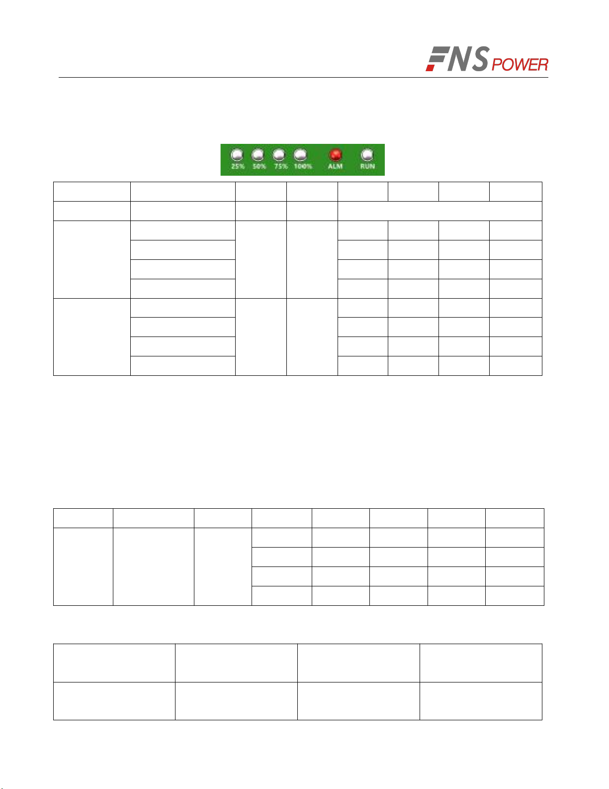
3. SOC: These 4 LEDs are used to display the pack SOC. The lightning of these LEDs indicates the
SOC of 25%, 50%, 75%, and 100%. For example, when SOC >75%, all 4 LEDS will be light up. If
SOC> 50% and <75%, 3 LEDs will be light up. Etc.
4. ALM: Warning light;
5. RUN: Indicate the alarm or the run status of the battery.
6. RS485: Communication interface: Used for RS485/CAN communication;
7. RS232: Connect with upper computer for battery system debugging and software upgrade.
8. Handle: It was used to carry/move the battery.
9. Used for fixing with cabinet.
10. Positive output terminal.
11. Negative output terminal.
12. Grounding bolt.
13. External switch interface.
2.2 Product Specifications
Table 2-1: Product Specifications

4
Basic Parameters
Model
FCIFP48100A
Anode Material
LiFePO4
Nominal Voltage(V)
48
Layout
15S1P
Rated Capacity(Ah)
100(0.5C,25℃)
Rated Energy(kWh)
4.8
Dimensions(W×D×H)mm
440×440×133(3U)
Weight(kg)
42(About)
Communication
RS485,CAN
Cycle Life
6000+(80%DOD,25℃)
Electrical Characteristics
Voltage Window(V)
40.5~54
Charge Current(A)
50(Recommend)
Max Charge Current(A)
100
Max Discharge Current(A)
100
Operation Environment
Charge Temperature(℃)
0℃~50℃(Optimum15℃~30℃)
Discharge Temperature(℃)
﹣20℃~50℃(Optimum5℃~45℃)
Storage Temperature(℃)
﹣20℃~55℃
Storage Humidity(RH)
5%~90%
Working Humidity(RH)
5%~90%
Protection Class
IP20
Products specifications described herein are subject to change without prior notification.
5
2.3 State Indicator
Table 2-2: Unprotected fault working mode
State
SOC(%)
RUN
ALM
25%
50%
75%
100%
shutdown
No light
No light
All no light
Standby/Disc
harge
0-25%
Flash
No light
Light
No light
No light
No light
25-50%
Light
Light
No light
No light
50-75%
Light
Light
Light
No light
75-100%
Light
Light
Light
Light
Charge
0-25%
Flash
No light
Flash
No light
No light
No light
25-50%
Light
Flash
No light
No light
50-75%
Light
Light
Flash
No light
75-100%
Light
Light
Light
Flash
Note: Flash: Light 0.5s, No light 0.5s
Table 2-3: Protected fault working mode
When the BMS detects a protection fault, the RUN indicator flashes from on for 0.5s to off for 0.5s, to
off for 0.5s and then on, waits for the ALM indicator to turn off for 0.5s after flashing according to the
fault, and repeats this cycle.
State
RUN
ALM
SOC(%)
25%
50%
75%
100%
Protection
status
No light 0.5s
and always
Light
Fault
content
0-25%
Light
No light
No light
No light
25-50%
Light
Light
No light
No light
50-75%
Light
Light
Light
No light
75-100%
Light
Light
Light
Light
Table 2-4: Fault code
RUN always Light and
ALM flashes
Fault
RUN always Light and
ALM flashes
Fault
1
Total pressure high
13
Ambient high
temperature

6
2
Total pressure low
14
Analog front end Fault
3
Cell voltage is too high
15
EEPROM Fault
4
Cell voltage is too low
16
short circuit Fault
5
Monomer high
temperature
17
low SOC
6
Monomer low
temperature
18
temperature rise too
fast
7
high differential
pressure
19
Precharge failed
8
low temperature
difference
20
MOS out of control
9
Overcurrent
21
ADC Fault
10
Voltage cable
22
limit Fault
11
temperature cable
23
Customize
12
MOS High
temperature Fault
24
Customize
3. Unpack the Battery
The battery and the related accessories are packed in the carton box and steel belt wooden box. Use
tools to open the packing box. After open the packing box, confirm the product components according
to the parts list.
3.1 Parts List
Check the parts during unpacking.
Violent unpacking is strictly prohibited. If the battery system is found to be
broken, deformed or other abnormal conditions, the user shall immediately
stop using the battery and contact us.
7
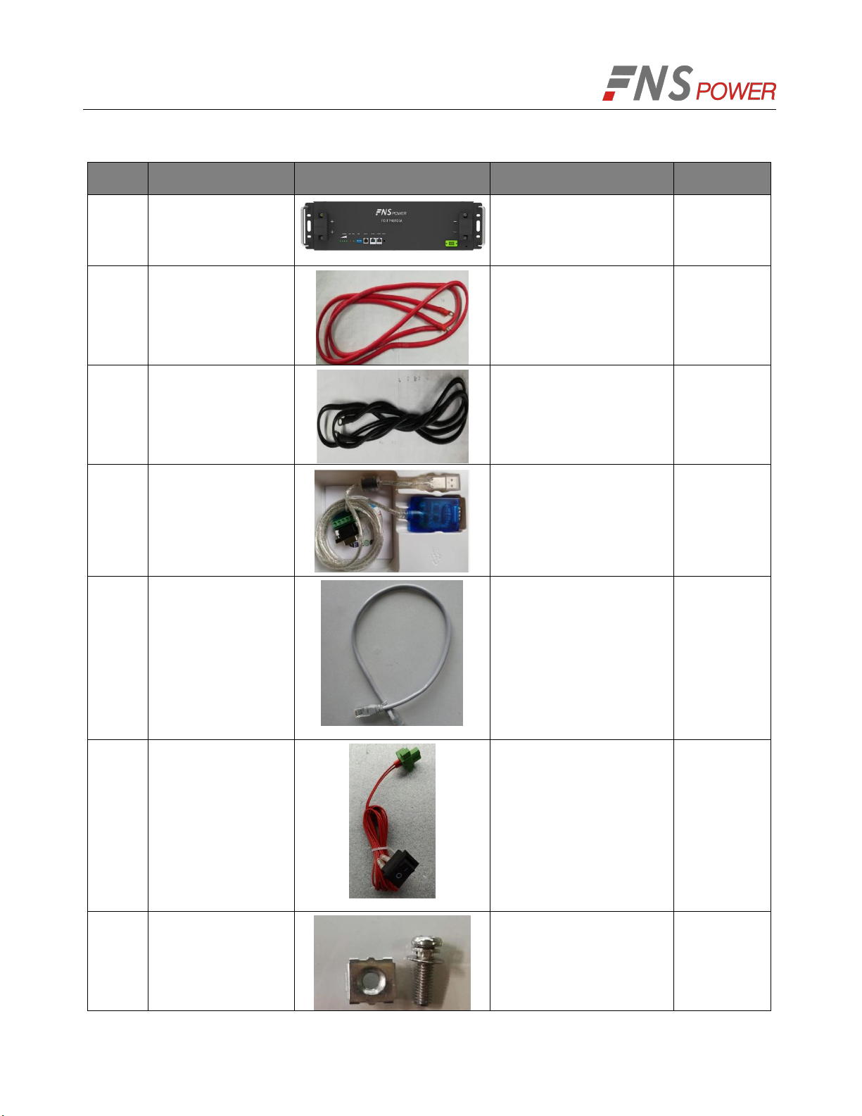
Table 3-1: Parts Lists
No.
Items
Appearance
Usage
Remarks
1
Battery
Provide power
2
Positive output
cable
Connect the battery and
inverter
3
Negative output
cable
Connect the battery and
inverter
4
RS485
communication
line
Apply to Modbus
protocol. Connect the
battery and the
computer.
Used to
monitor and
debug the
battery
(Optional)
5
RS485
communication line
Battery cascade line.
Connect the RS485
communication interface
between the adjacent
battery
Standard
RJ45
network
cable
6
External switch line
Battery external switch
7
Cabinet bolt
Fix the battery on the
rack or cabinet

8
Table 3-2: Recommended Tools and Instruments
No.
Items
Usage
Appearance
1
Phillips Screwdriver or Bit
To fasten battery and
assemblies
2
Box Cutter
Opening boxes
3
Insulated Torque Wrench
Installing cables and busbars
4
Insulated Sockets
Installing cables and busbars
5
Battery Tester
Measure battery module’s
voltage
3.2 Visual Inspection of the Modules
After transporting the modules to the installation location, check for:
Physical damage to the exterior
Damaged or protruding screws
4. Battery Installation
This system must be installed by qualified, trained workers familiar with the required instruments.
9
Be sure to use insulated tools (torque wrench, extension, socket, etc.).
All the instruments must be insulated and no metal articles (e.g. watch,
ring) should be present in the installation area.
All power switches must be turned off in advance.
Prepare a CO2fire extinguisher, a first aid kit, and an AED (automated
external defibrillator) before installation.
Arc Flash and Shock Hazard
Insulated tools are required for any work on this energized equipment.
Sharp Edges
Wear gloves and other protective gear to prevent injury.
Pinch Point
Use caution when working in the enclosure to prevent injury.
Heavy Object
Can cause muscle strain or back injury.
Use lifting aids and proper lifting techniques when moving trays, batteries
and other heavy objects.
4.1 Battery Module Installation
1. Transport battery modules to the installation location.
3. Place the battery modules on the rack frame or cabinet.
4. Fix the battery on the rack. Using the cabinet bolt to fix the battery into the hole on the rack.
5. After installation, tighten all bolts.
10
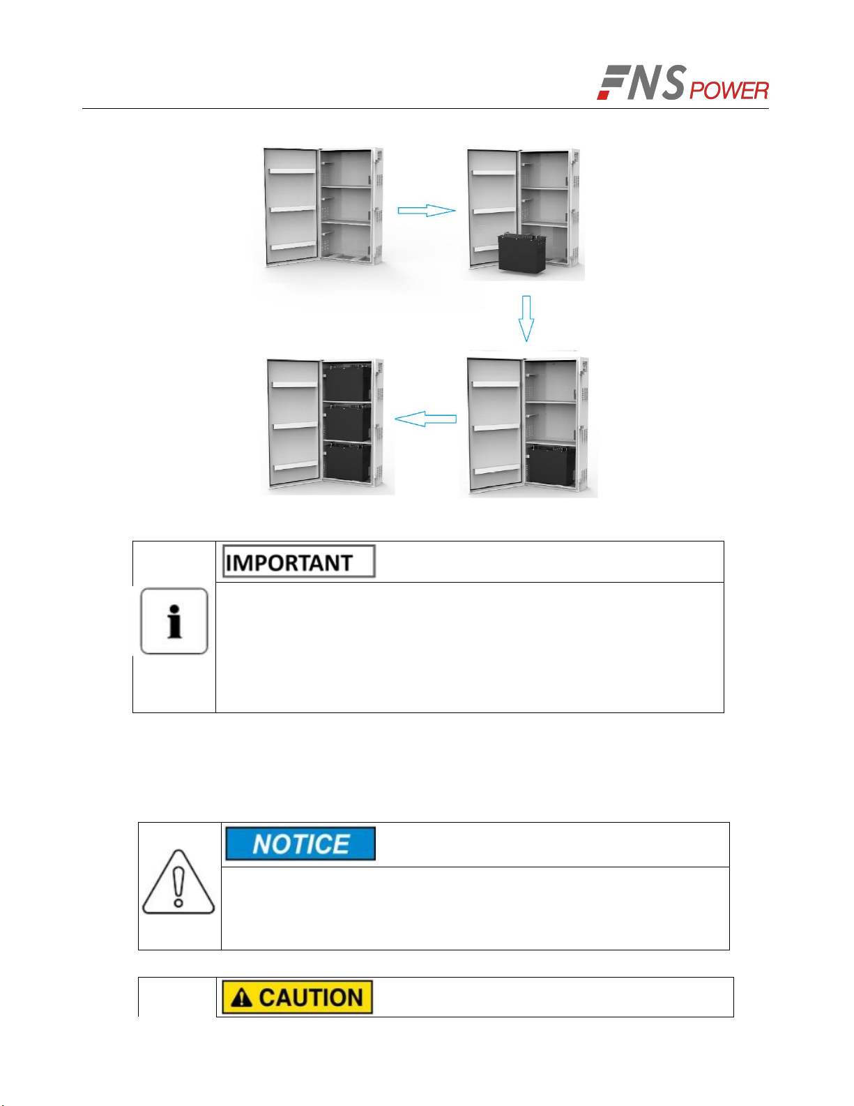
Figure 4-1: Battery Module Installation (A possible battery install procedure)
We recommends installing battery modules in the upper shelves first
and proceeding to the bottom.
The battery can be mounted on a standard 19 inches cabinet or rack.
Battery modules can be inserted into a rack frame according to the
customer battery configuration scheme.
5. Cable Connection
5.1 Single Battery Connection
Before connect the cable with the inverter, the worker must confirm the
output switch of the inverter has been turn off, to prevent the risk of fire
or electric shock.

11
Before connection, make sure to close the battery.
Please follow the instructions to protect the module BMS against
damage.
DO NOT deviate from the sequence of steps below.
Exercise extreme caution prevent the terminals from contacting anything
except their intended mounting points.
Terminals and their connected wires have either positive or negative
polarity (Positive: +; Negative-). The polarity of a terminal or a wire
connected to the terminal is on the front of each module. Exercise
extreme caution to prevent the terminals and/or wires with opposite
polarity from contacting with each other.
In telecom and battery, it is typically designed that positive is grounded.
Therefore, it is necessary to avoid any non-insulating contact between
the negative terminal and the positive terminal of the battery or the rack
during the connection process. This can effectively avoid issues such as
sparking or short circuit.
The maximum voltage of the battery is no more than 60V, which is higher
than the safe voltage of 36V. Therefore, we still recommend that the
battery terminals or other exposed parts should not be directly touched
When tightening the screws, make sure they are at a straight angle from
the battery module terminals to avoid damage to the nuts inside.
Assemble the screws using a Phillips-head within the fastening torque of
less than 8.0 Nm (79.88 kgf/cm).
The power terminals, such as “+,” “-,” of the module are covered with the
protecting cover to guard against a short circuit (Shown in Figure 5-1).
You must remove the insulation cover prior to connecting and reattach
the insulation cover immediately after connecting.
12
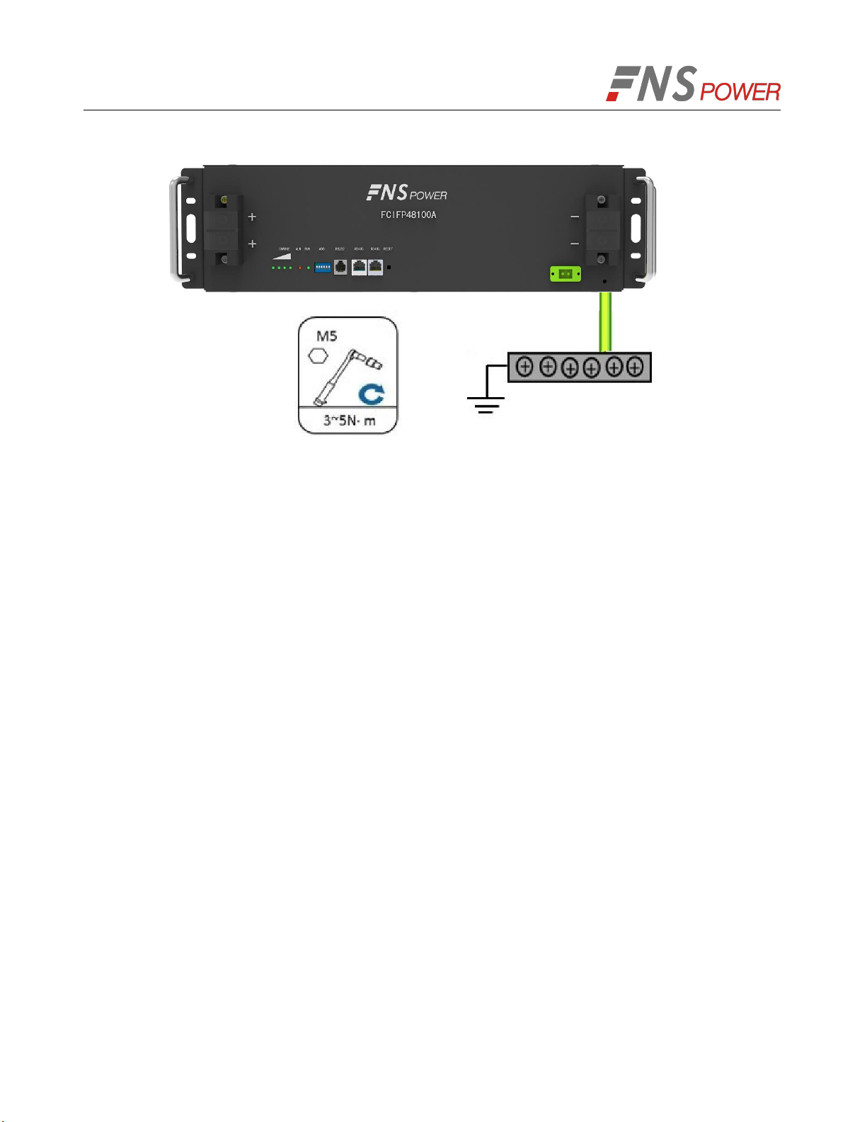
Figure 5-1: Install the Grounding Wire
Step 1 Wear the protective gloves. Step 2 Install the battery ground cable.
Step 3 Install negative and positive power cables for the battery.
1) Remove the protective cover from the battery power wiring terminal.
2) Connect the negative power cable to the battery.
3) Connect the positive power cable to the battery.
4) Install the other end of the battery power cables at a battery route and the corresponding RTN+
busbar in the power system.
5) Reinstall the protective cover on the battery power wiring terminals.
1. Remove the protecting cover.
2. Take-down positive fixing bolt by the Phillips Screwdriver and connect the positive output cable
between the battery positive terminal of the battery and the inverter. After connecting the battery,
fastening bolt immediately to avoid dropping.
13
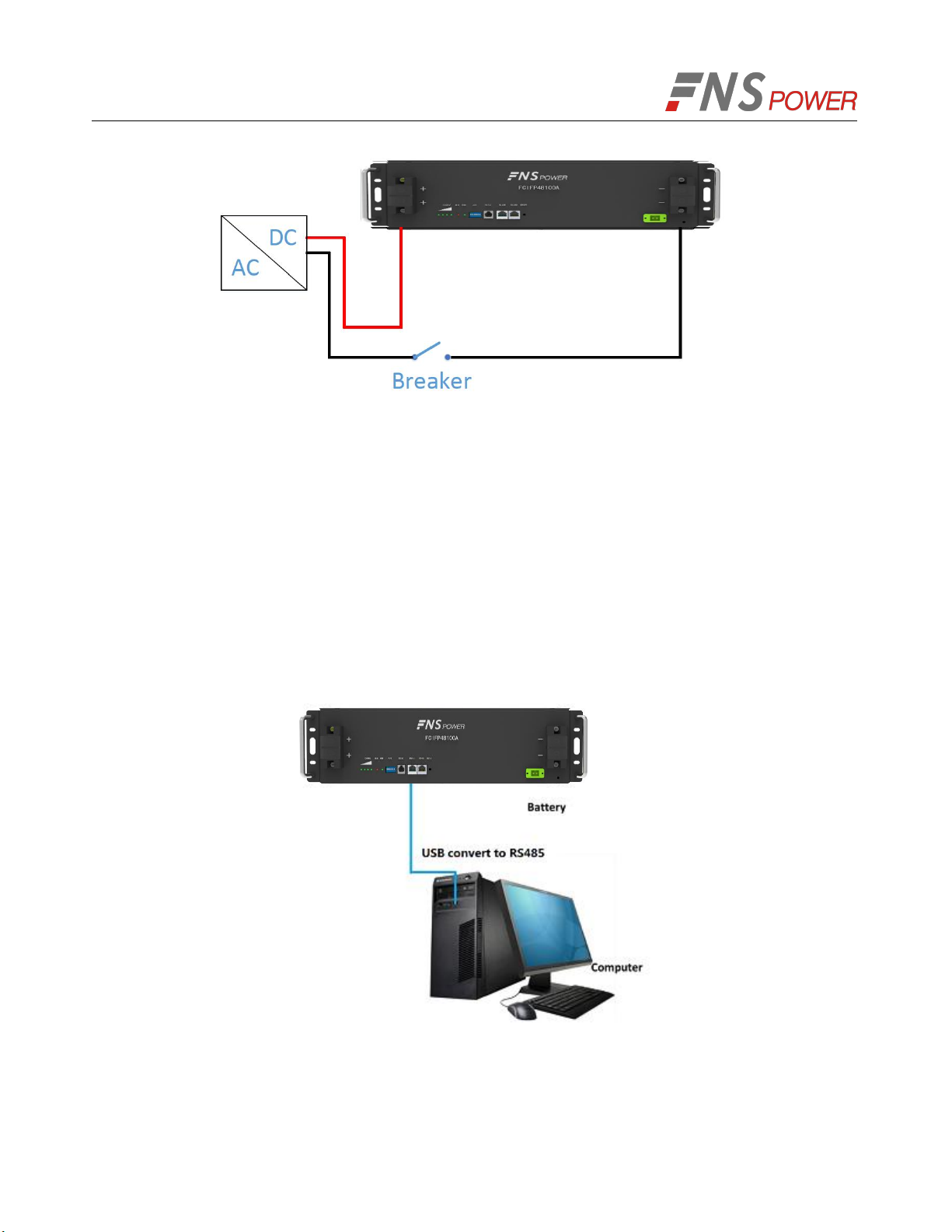
Figure 5-2: Single Battery Connection
3. Take-down negative fixing bolt by the Phillips Screwdriver and connect the negative output cable
between the battery negative terminal of the battery and the inverter. After connecting the battery,
fastening bolt immediately to avoid dropping.
4. Install the protecting cover.
5. Sort the cables and fasten the battery cables to the perforated bracket with cable ties.
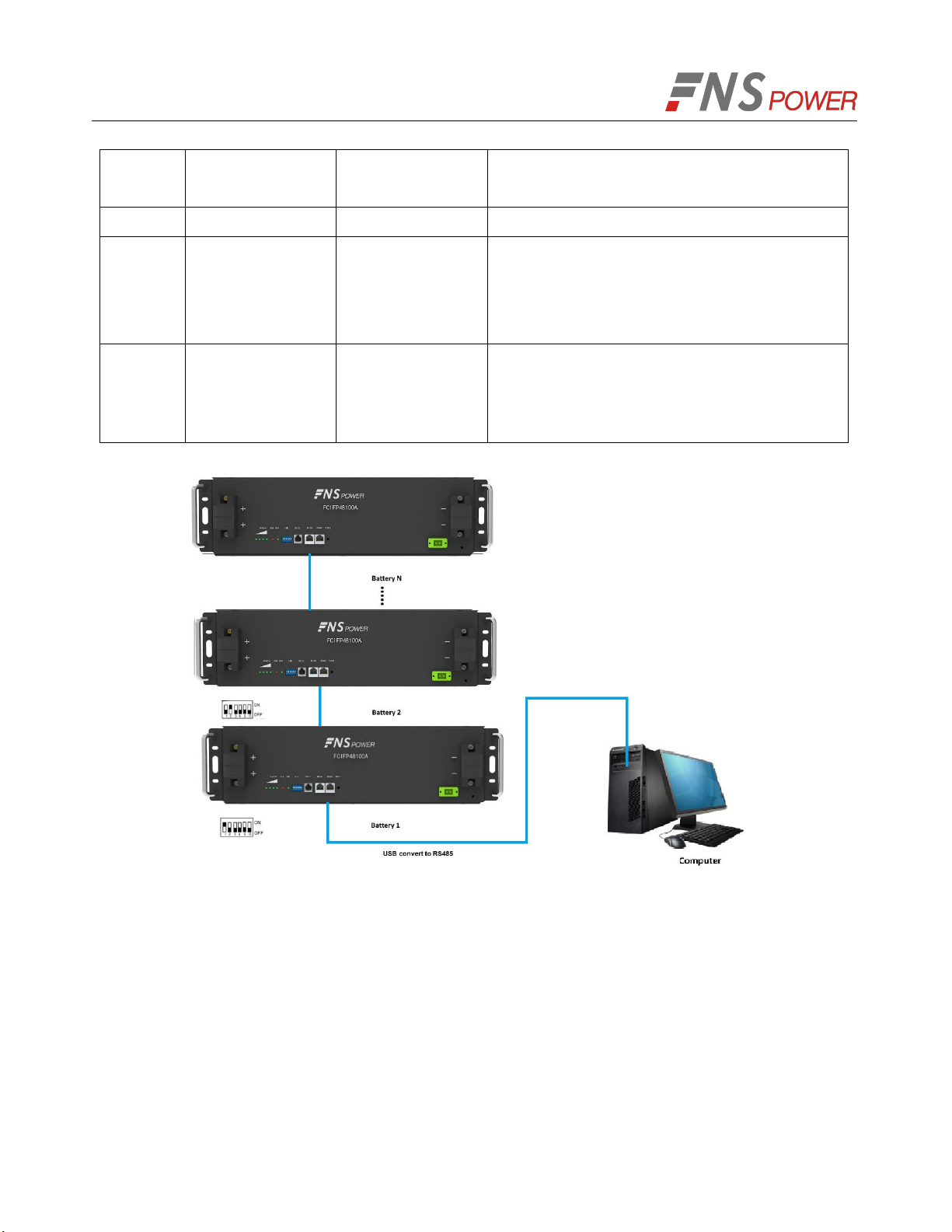
6. Communication Line Connection
As shown in Figure 5-4, when monitoring the battery by the computer, connect the ‘USB convert to
RS485’ communication line between battery and computer.
Figure 5-3: Communication Cable Connections between Battery and Computer
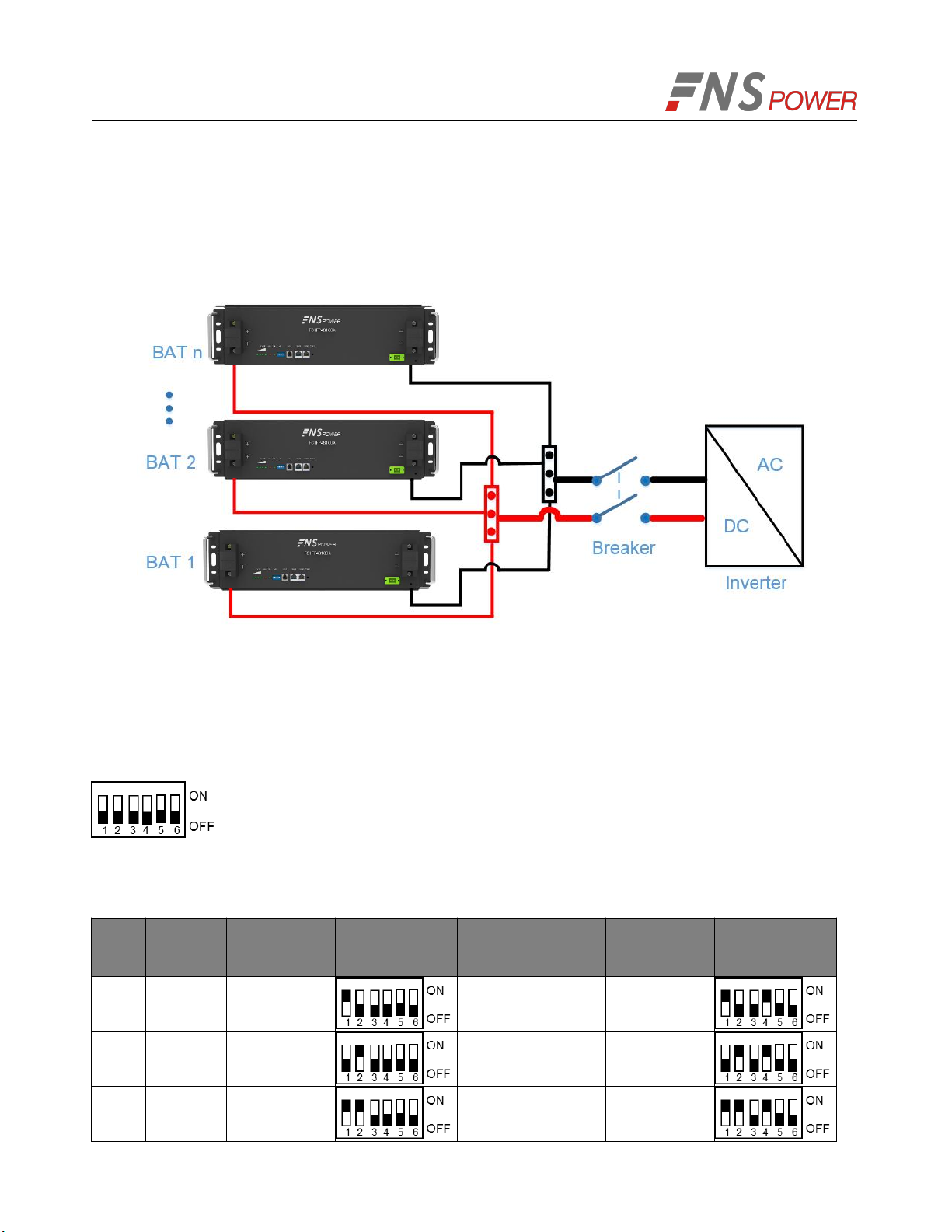
5.2 Connect Cables of the Multiple Batteries in Parallel
When multiple batteries in parallel, the cable connecting procedures are follows.
14
1. As shown in Figure 5-5, following the cable connection method of the single battery, connect the
positive and negative cables between the Battery 1 and the busbar, Battery 2 and the busbar, and
Battery N and the busbar respectively.
Note: To ensure the current balance, please use cables with the same diameter and length for each
battery.
Figure 5-4: Multiple Batteries Connections
2. As shown in Figure 5-7, connect the communication line (a standard RJ45 network cable) between
the adjacent batteries.
3. When performing multi-machine parallel communication operation, it need to configure the dialing
address of each battery. The dialing code is in BCD format, and the address 0 is defined as
. The dialing address configuration of each battery is shown in Table 5-1.
According to the number of the battery in parallel, set the dialing address of the corresponding battery.
Table 5-1: The Dialing Address Configuration of Each Battery
No.
Module
Address
Battery
Module ID
Picture
No.
Module
Address
Battery
Module ID
Picture
1
0x01
1
9
0x09
9
2
0x02
2
10
0x0a
10
3
0x03
3
11
0x0b
11

15
Note: After the DIP settings are changed, a restart is required to take effect.
4. Connect the communication line between battery and computer
(1) RS485/CAN Port Definition
(a) RJ45 Pin Male (b) RJ45 Pin Female
Figure 5-5: Communication Port
Table 5-2: Description of RJ45 Pin
RJ45 Pin
Signal
Meaning
Description
1
RS485 B
2-wire RS485 communication,
complying with the Modbus protocol
2
RS485 A
2-wire RS485 communication,
complying with the Modbus protocol
3
NC
Reserved
4
CAN H
2-wire CAN communication,
complying with the CAN protocol
4
0x04
4
12
0x0c
12
5
0x05
5
13
0x0d
13
6
0x06
6
14
0x0e
14
7
0x07
7
15
0x0f
15
8
0x08
8
16
5
CAN L
2-wire CAN communication,
complying with the CAN protocol
6
NC
Reserved
7
RS485 A
RS485 communication,
complying with the Modbus protocol,
connect to Pin2 in parallel
8
RS485 B
RS485 communication,
complying with the Modbus protocol,
connect to Pin1 in parallel
Figure 5-6: Communication Cable Connections among Multiple Batteries
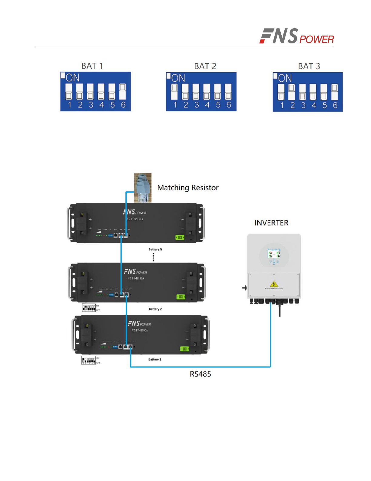
5.Connect the communication line between battery and inverter
Keep the battery off.
Connect the inter-battery communication cascade.
RS485 communication line connecting the inverter to the battery.
Adjust the DIP switch, the largest dip switch address is the last battery.
When the batteries are connected in parallel, the DIP bit (sixth bit) of the first battery and the
last battery must be turned to ON. The following three are connected in parallel.
17
When the battery communicates with the inverter through RS485, the matching resistor must
be inserted into the RS485 connector of the last battery in parallel.
Note: When only one battery is connected to the inverter communication, a matching resistor
is also inserted.
Figure 5-7: Multiple batteries connected to the inverter
Table of contents
Other FNS POWER Batteries Pack manuals

Popular Batteries Pack manuals by other brands

Anton/Bauer
Anton/Bauer Interactive 2000 PowerCharger owner's manual

Pylontech
Pylontech Force-L2 product manual

Beltrona
Beltrona SNE5126LFP-BL user manual

Inventus Power
Inventus Power PROTRXion M-24V60-TRX user manual

Middle Atlantic Products
Middle Atlantic Products UPS-OLEBPR-1 user manual

Solar Stik
Solar Stik 24VDC POWER HUB 2400 Operator and maintenance manual


