FNS POWER FSHM05010AUN User manual

User Manual

2
Read this manual carefully before starting to install the all-in-one
system.
Keep these instructions for future reference.
This document contains information that is the property of FnS Power Technology Inc., andprovides
for the sole purpose of the installation, connection, and maintenance of products of FnS Power
Technology Inc. No part of this publication is to be used for any other purpose, and it is not to be
reproduced, copied, disclosed, transmitted, storedin a retrieval system, or translated intoany
human
or computer language, in any form, by any means, in whole or in part, without prior written
consent
of FnS Power Technology Inc.
Although every possible effort has been made to ensure the accuracy of this document,FnS Power
Technology Inc. assumes no responsibility for errors that may appear herein. The information is
subject to change without notice.
3
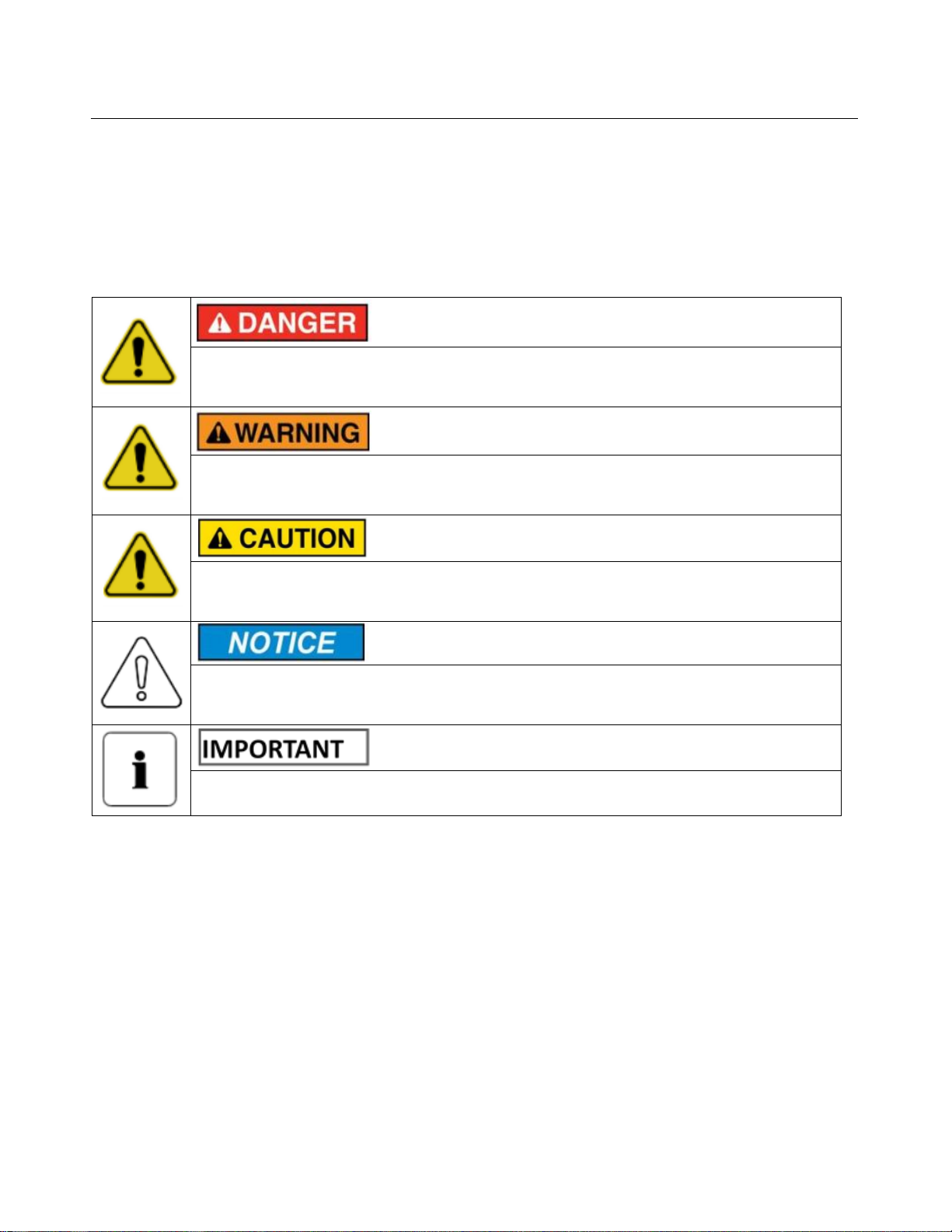
Read and follow these instructions!
The following precautions are intended to ensure your safety and prevent property damage. Before
installing this product, be sure to read all safety instructions in this document for proper installation.
Failure to comply with the instructions with this symbol may result in a serious
accident, causing death or a severe injury.
Failure to comply with the instructions with this symbol may result in a serious
accident, causing a severe injury.
Failure to comply with the instructions with this symbol may result in minor or
moderate injury.
Provides information considered important but not hazard-related. The information
relates to property damage.
Indicates valuable tips for optimal installation and operation of the product
This product is designed to an integrated system, which must be performed by a qualified person
trained in electrical engineering and familiar with the characteristics and safety requirements of lithium
batteries. Do not use this product if you are unsure if you possess the necessary skills to complete this
integration.

4
Table of Contents
1. Precautions.................................................................................................................................9
1.1 General Safety Precautions......................................................................................................9
1.2 Installation Precautions.............................................................................................................9
2. Product Introduction..................................................................................................................10
2.1 Product Specifications ............................................................................................................11
2.2 Product Overview of the Cabinet ............................................................................................13
2.3 Front Panel Function Introduction of the Battery.....................................................................14
2.4 State Indicator ........................................................................................................................16
2.5 Inverter Overview....................................................................................................................17
2.6 Inverter Function Port Definition..............................................................................................19
3. Unpack the Product...................................................................................................................20
3.1 Parts List ................................................................................................................................20
3.2 Inspecting the Cabinet............................................................................................................21
3.3 Inspection of the Modules.......................................................................................................22
4. Installation of the System .............................................................................................................22
4.1 Open the Cabinet Door...........................................................................................................23
4.2 Install the Inverter...................................................................................................................24
4.3 Confirm the Cabinet Installation Position ................................................................................24
4.4 Install of the Cabinet Mounting Plate.......................................................................................25
4.5 Install of the Cabinet on the Wall ............................................................................................26
4.5.1 Install the Stainless Steel Ani-collision Bolt.......................................................................26
4.5.2 Install of the Cabinet on the Wall......................................................................................26
4.6 Place the Battery ....................................................................................................................27
4.7 Busbar to Battery Cable Connection and Communication Cable Connection..........................28
4.8 Fasten the Battery ..................................................................................................................30
5. Cable Connection.........................................................................................................................31
5.1 Inverter to Breaker Cable Connection.....................................................................................31
5.2 Inverter to Switch Cable Connection.......................................................................................32
5.3 External Power Supply to Switch Cable Connection...............................................................33
5.4 Earth Connection between Inverter and Cabinet (mandatory).................................................34
5.5 Earth Connection between Battery and Cabinet......................................................................35
Table of Contents

5
5.6 Earth Connection between Ground and Cabinet.....................................................................36
5.7 PV Connection .......................................................................................................................37
5.8 PV Module Selection: .............................................................................................................37
5.9 CT Connection .......................................................................................................................38
5.10 Meter Connection.................................................................................................................39
5.11 WIFI Connection...................................................................................................................40
5.12 Wiring System for Inverter ....................................................................................................40
5.13 Single Phase Parallel Connection Diagram ..........................................................................42
5.14 Three Phase Parallel Inverter ...............................................................................................43
5.15 Visual Inspection of the Connection......................................................................................44
6. Activate the Product.....................................................................................................................45
6.1 Power ON/OFF.......................................................................................................................45
6.2 Operation and Display Panel ..................................................................................................45
6.3 LCD Display Icons..................................................................................................................45
6.4 LCD Operation Flow Chart......................................................................................................47
6.5 Solar Power Curve..................................................................................................................47
6.6 Curve Page-Solar & Load & Grid ...........................................................................................49
6.7 System Setup Menu ...............................................................................................................50
6.8 Basic Setup Menu...................................................................................................................50
6.9 Battery Setup Menu................................................................................................................51
6.10 System Work Mode Setup Menu ..........................................................................................54
6.11 Grid Setup Menu...................................................................................................................56
6.12 The method of CEI-021 Standard Self-Check.......................................................................58
6.13 Generator Port Use Setup Menu...........................................................................................60
6.14 Advanced Function Setup Menu...........................................................................................61
6.15 Device Info Setup Menu........................................................................................................62
7. Mode............................................................................................................................................62
8. Inspection, Cleaning and Maintenance.........................................................................................65
8.1 General Information................................................................................................................65
8.2 Inspection...............................................................................................................................66
8.3 Cleaning.................................................................................................................................66
8.4 Maintenance...........................................................................................................................66
8.5 Storage...................................................................................................................................66

6
9. Troubleshooting ...........................................................................................................................67
9.1 Troubleshooting of the Battery................................................................................................67
9.2 Troubleshooting of the Inverter...............................................................................................68
10. Transportation Requirements.....................................................................................................72

7
About this Manual
To make sure that you understand the proper procedures for safe operation, this section briefly
describes the purpose, audience, organization, revision history, and acronyms and abbreviations.
Purpose
The purpose of this manual is to provide information for the safe and successful installation of the
product. The instructions in this manual are based on assembly of a three-cabinet system. Other
configurations are possible and theses instructions can be reduced or expanded to accommodate
installation of those systems.
Target Audience
This installation manual is intended for system administrators and operators who install and configure
the product.
Organization
This manual is composed of the following chapters:
Chapter 1, “Precautions,” list the considerations.
Chapter 2, “Product Introduction,” explains the function of the product.
Chapter 3, “Unpack the Product,” explains how to unpack the battery.
Chapter 4, “Installation of the System,” explains how to install the product.
Chapter 5, “Cable Connection,” explains how to connect the product.
Chapter 6, “Activate the Product,” explains how to activate the product, to begin using the
battery.
Chapter 7, “Mode,” explains the product mode.
Chapter 8, “Inspection, Cleaning and Maintenance,” explains how to carry out the maintenance
and store the product.
Chapter 9, “Troubleshooting,” explains some troubleshooting when some fault phenomenon
occur.
Chapter 10, “Transportation Requirements,” explains transportation requirements.

8
Revision History
Rev.
Description
Author
Date
0.1
First Release
2022.03.18
0.2
Add inverter description and
installation guide
2022.08.31
0.3
Modify according to the client.
2023.01.09
Acronyms and Abbreviations
The following acronyms and abbreviations are used in this manual
Abbreviations
Full Name
BMS
Battery Management System
SOC
State Of Charge
SOH
State Of Health
GEN
Generator
PV
Solar Photovoltaic

9
1. Precautions
1.1 General Safety Precautions
The product provides a safe source of electrical energy when operated as intended and as designed.
Potentially hazardous circumstances such as excessive heat or electrolyte mist may occur under
improper operating conditions, damage, misuse and/or abuse. The following safety precautions and
the warning messages described in this part must be observed.
If any of the following precautions are not fully understood, or if you have any questions, contact us
for guidance.
Risks of explosion
Do not subject the battery pack to strong impacts.
Do not crush or puncture the battery pack.
Do not dispose of the battery pack in a fire.
Risks of fire
Do not expose the battery pack to temperatures in excess of 122 ℉.
Do not place the battery pack near a heat source such as a fireplace.
Do not expose the battery pack to direct sunlight.
Do not allow the battery connectors to touch conductive objects such as wires.
Risks of electric shock
Do not disassemble the battery pack.
Do not touch the battery pack with wet hands.
Do not expose the battery pack to moisture or liquids.
Keep the battery pack away from children and animals.
Risks of damage to the battery pack
Do not allow the battery pack to come into contact with liquids.
Do not subject the battery pack to high pressures.
1.2 Installation Precautions
Please be aware that a battery presents a risk of electrical shock including high short-circuit current.
Follow all safety precautions while operating the batteries and the inverter.
Remove watches, rings, and other metallic accessories.
Use tools with insulated handles in order to avoid inadvertent short circuits.
Precautions

10
Wear rubber gloves and safety boots.
Do not put tools or any metal parts on the top of the batteries.
Disconnect charging source and load before connecting or disconnecting terminals.
Use proper lifting means when moving batteries and wear all appropriate safety clothing and
equipment.
Do not open or mutilate the batteries.
Do not disassemble the inverter. If you need maintenance or repair, take it to a professional
service center.
To reduce risk of electric shock, disconnect all wires before attempting any maintenance or
cleaning. Turning off the unit will not reduce this risk.
Never charge a frozen battery.
Be very cautious when working with metal tools on or around batteries. Dropping a tool may
cause a spark or short circuit in batteries or other electrical parts, even cause an explosion.
Grounding instructions - this inverter should be connected to a permanent grounded wiring
system. Be sure to comply with local requirements and regulation to install this inverter.
Never cause AC output and DC input short circuited. Do not connect to the mains when DC
input short circuits.
▪Verify polarity at all connections before energizing the system. Reverse polarity at
the battery terminals will void the Warranty and destroy the batteries. Do not short
circuit the batteries.
▪Do not combine FnS Lithium Batteries with other brands or chemistries; Do not mix
Lithium Batteries from different installations, clients, or job sites.
▪Do not disassemble or modify the battery. If the battery housing is damaged, do not
touch exposed contents.
2. Product Introduction
All-in-one energy storage system consists of LFP battery modules, hybrid inverter and advanced
remote monitoring App. It is pre-programmed ESS for backup power, TOU, zero export, peak shaving
and self-consumption of solar PV. ATS automatically disconnects from the grid during power outages
Product Introduction

11
and provides standby power for critical circuits.
2.1 Product Specifications
Table 2-1: Product Specifications
PV String Input Data
Model
FSHM05010AUN
Max Recommended PV Power (w)
6500W
PV Input Voltage(V)
370V(125V~500V)
MPPT Range(V)
150V~425V
Start-up Voltage(V)
125V
PV Input Current(A)
13A+13A
No .of MPPT Trackers
2
No. of MPPT Strings Per MPPT Tracker
1+1
Battery Data
Battery Type
LiFePO4
Nominal Voltage(V)
48V
Battery Voltage Range(V)
47.5~54V
Max Charging / Discharging Current(A)
120A
Battery Storage Capacity(kWh)
9.6kWh
AC Output Data
Rated AC Output and UPS Power(W)
5000W
Max AC Apparent Power (W)
5000W
AC Output Rated Current (A)
21.7A
Output Frequency and Voltage
50Hz; 230/240Vac
Grid Type
Single Phase
General Data
Product Introduction

12
Operating Temperature Range (℃)
-20℃~50℃
Noise(dB)
<30dB
Max. Efficiency
97.6%
Communication With BMS
RS485, CAN
Weight(kg)
180kg
Size(W×D×H) mm
645×272×1600mm
General Data
Grid Regulation
CEI0-21,VDE-AR-N4105, NRS097,
IEC62116, IEC61727,G99,G98,
VDE0126-1-1,RD1699.C10-11
Safety EMC/Standard
IEC/EN62109-1/-2,IEC/EN61000-6-1/-2/-3/-4
Battery
UL1642, UL1973, CE,IEC62133,UN38.3,
UL9540A
Product Introduction

13
2.2 Product Overview of the Cabinet
Figure 2-1: Function Introduction
1. LCD display. It can see the battery information.
2. Fixing plate. A mounting plate for securing the cabinet on wall.
3. Power on/off button. You can use this button to start the inverter.
4. Input port of the power supply, such as grid, load, gen, and PV.
5. Battery. This battery ADD address is 1.
6. Battery. This battery ADD address is 2.
7. Inverter.
8. The front cover of the cabinet.
Product Introduction

14
2.3 Front Panel Function Introduction of the Battery
Figure 2-2: Front Panel Function Introduction
1. Reset: Reset button, when the system is abnormal, you can use this button to reset and restore
the normal operation of the system. When the RUN lamp is flashing, press the reset button until all
the LED lights flash to reset the battery group; all LED lights are off. Under the state, press the reset
button, all the lights turn on the battery group in turn; RUN light is on, press the reset button RUN
light off to turn off the battery;
2. RS485 communication interface: Used for cascade communication or MODBUS communication;
(1) RS485/CAN Port Definition
(a) RJ45 Pin Male (b) RJ45 Pin Female
Figure 2-3: Communication Port
Product Introduction

15
Table 2-2: Description of RJ45 Pin
RJ45 Pin
Signal
Meaning
Description
1
RS485 B
2-wire RS485communication,
complying with the Modbusprotocol
2
RS485 A
2-wire RS485communication,
complying with the Modbusprotocol
3
NC
Reserved
4
CAN H
2-wire CANcommunication,
complying with the CANprotocol
5
CAN L
2-wire CANcommunication,
complying with the CANprotocol
6-8
NC
Reserved
3. ADD: DIP switch, used for setting the product communication address when communication
cascade;
Table 2-3: The Dialing Address Configuration of Each Battery
No.
Module
Address
Battery
Module ID
Picture
No.
Module
Address
Battery
Module ID
Picture
1
0x01
1
9
0x09
9
2
0x02
2
10
0x0a
10
3
0x03
3
11
0x0b
11
4
0x04
4
12
0x0c
12
5
0x05
5
13
0x0d
13
6
0x06
6
14
0x0e
14
7
0x07
7
15
0x0f
15
8
0x08
8
Product Introduction

16
4. RUN: Run light;
5. ALM: Warning light;
6. SOC: These 4 LEDs are used to display the pack SOC. The lightning of these LEDs indicates the
SOC of 10%, 25%, 50%, and 75%. For example, when SOC >75%, all 4 LEDS will be light up. If
SOC> 50% and <75%, 3 LEDs will be light up. Etc.
7. The pack’s negative (-) electrode.
8. The pack’s positive (+) electrode.
9. Used for fixing with racks.
10. Handle: It was used to carry/move the battery.
Products specifications described herein are subject to change without prior notification.
2.4 State Indicator
Table 2-4: State Indicator
System Mode
Abnormal event
RUN
ALM
Capacity LED
De-energized/
shutdown Mode
No light
No light
All no light
Stand-by Mode
Normal
Flash 1
No light
Indicate the SOC
Alarm
Flash 1
Flash 2
Indicate the SOC
Charging
Normal
Light
No light
Indicate the SOC, the higher LED
flash 2
Alarm
Light
Flush 2
Indicate the SOC, the higher LED
flash 2
Over charge
protection
Light
No light
All light
Temp
protection
Flash 1
Flash 2
Indicate the SOC
Overcurrent,
fail protection
No light
Light
All no light
Discharging
Normal
Flash 3
No light
Indicate the SOC
Alarm
Flash 3
Flash 2
Indicate the SOC
Product Introduction

17
Low voltage
protection
Flash 3
No light
All no light
Overcurrent,
Short Circuit
protection
No light
Light
All no light
Failure
No light
Light
All no light
Flush 1: Light 0.25s and no light 3.75s; Flash 2: Light 0.50s and no light 0.50s;
Flush 3: Light 0.50s and no light 1.50s
2.5 Inverter Overview
Figure 2-4: Inverter Overview
1: Inverter Indicators
2: LCD display
Product Introduction

18
3: Function Buttons
4: Battery input connectors
5: RS 485 Port: for energy RS 485 communication.
6: BMS CAN Port: CAN port for battery communication.
7: Meter Port: for energy meter communication.
8: Function Port
9: Parallel port: Parallel communication port 1(CAN interface).
10: Generator input
11: Load
12: Grid
13: Power on/off button
14: DC Switch
15: PV input with two MPPT
16: Battery
17: Temperature sensor
18: WiFi Interface
Product Introduction

19
2.6 Inverter Function Port Definition
Figure 2-5: Inverter Function Port
Product Introduction

20
3. Unpack the Product
The cabinet, battery and the related accessories are packed in the steel belt wooden box. Use tools
to open the steel belt on the upper cover plate of the packing box. After opening the packing box,
confirm the product components according to the parts list.
Violent unpacking is strictly prohibited. If the all-in-one system is found to be broken,
deformed or other abnormal conditions, the user shall immediately stop using the
battery and contact us.
3.1 Parts List
Check the part during unpacking.
Table 3-1: Parts Lists of the battery
Part No.
Items
Appearance
Usage
Remarks
1
RS485
communication
line
Apply to
Modbus
protocol.
Connect the
battery and the
computer.
Used to
monitor and
debug the
battery
2
Mounting Plate
for Battery
Fixation
Fix the battery
on the cabinet
These
three parts
are fixed in
the cabinet
when
packaging.
3
Sheet-metal
Part for
Cabinet Fixation
Fix the battery
on the wall
Unpack the Product
Table of contents
Other FNS POWER Batteries Pack manuals

Popular Batteries Pack manuals by other brands


Parkside
Parkside 302268 operating instructions

ToughTested
ToughTested TT-PBW-SW8 user manual

XD COLLECTION
XD COLLECTION XD P322.16 Series manual

SilentGreen
SilentGreen RPS product manual

UPOWER Ecoline
UPOWER Ecoline NauticBattery NA-12LI22BL quick start guide

Greencut
Greencut BAT-56V-2AH operating instructions