Beltrona SNE5126LFP-BL User manual

User Manual
Model: SNE5126LFP-BL


- 1 -
Contents
Safety Precautions ....................................................................................................................................................- 2 -
1.1.Before Connecting .......................................................................................................................................... - 2 -
1.2.During Operation ............................................................................................................................................- 2 -
2.Battery Introduction ..............................................................................................................................................- 3 -
2.1 Main Features .................................................................................................................................................- 3 -
2.2 Battery Specifications ..................................................................................................................................... - 3 -
3. Interface area ......................................................................................................................................................- 5 -
3.1 Battery status indicator .................................................................................................................................. - 5 -
3.2 Battery Capacity Indicator .............................................................................................................................. - 6 -
4. Installation ............................................................................................................................................................- 6 -
4.1 Tools ................................................................................................................................................................- 6 -
4.2 List of items .....................................................................................................................................................- 7 -
4.3 Installation Location ....................................................................................................................................... - 7 -
4.4 Minimum clearances ...................................................................................................................................... - 8 -
4.5 Installing the Battery Pack .............................................................................................................................. - 8 -
4.6 Parallel use of battery .....................................................................................................................................- 9 -
4.7 Communication Connection ........................................................................................................................ - 10 -
4.7.1 Communication Address Setting ........................................................................................................... - 10 -
4.7.2 Communication between battery and inverter .....................................................................................- 11 -
4.7.3 Communication interface definition ......................................................................................................- 12 -
4.8 Power-on and power-off .............................................................................................................................. - 13 -
5. Product responsibility and consulting ................................................................................................................- 13 -

- 2 -
1.Safety Precautions
It is very important and necessary to read the user manual carefully before installing or using the
battery. Failure to follow any of the instructions or warnings in this document can result in electrical
shock, serious injury, death, or may damage the battery and the whole system.
If the battery is stored for a prolonged time, it is requirement that they are charged every three to six
months, and the SOC should be no less than 80%.
The battery needs to be recharged within 12 hours, after fully discharging.
Do not expose cable outside.
All battery terminals must be disconnected before maintenance.
Do not use cleaning solvents to clean the battery.
Do not expose the battery to flammable or harsh chemicals or vapors.
Do not paint any part of the battery, include any internal or external components.
Do not connect battery with PV solar wiring directly.
Any foreign object is prohibited to be inserted into any part of the battery.
Any warranty claims are excluded for direct or indirect damage due to items above.
1.1.Before Connecting
After unpacking, please check the battery and packing list first, if the battery is damaged or spare
parts are missing, Please contact the dealer.
Before installation, be sure to cut off the grid power and make sure the battery is in the turned-off
mode;
Wiring must be correct, do not mix-connect the positive and negative cables, and ensure no short
circuit with the external device;
It is prohibited to connect the battery with AC power directly;
The embedded BMS in the battery is designed for 51.2VDC, please DO NOT connect battery in
series;
It is prohibited to connect the battery with different type of battery;
Please ensure the electrical parameters of battery system are compatible to inverter;
Keep the battery away from fire or water.
1.2.During Operation
If the battery system needs to be moved or repaired, the power must be cut off first and the battery is
completely shutdown;
It is prohibited to connect the battery with different type of battery;
It is prohibited to put the batteries working with faulty or incompatible inverter;
In case of fire, only dry powder fire extinguisher can be used, liquid fire extinguishers are prohibited;

- 3 -
Please do not open, repair or disassemble the battery. We do not undertake any consequences or
related responsibility due to violation of safety operation or violating of design, production and
equipment safety standards.
2.Battery Introduction
This document describes the parameters, features, operation methods, and precautions of SNE series
wall-mounted lithium iron phosphate battery storage system.
Please read this manual carefully before installing the battery, and follow the instructions strictly during
the installation. If you have any questions, please contact customer service immediately for advice and
assistance.
2.1 Main Features
LiFePO4 components - for superior safety and service life;
High safety and reliability;
5000 cycles /5 years service life;
Consistent performance over a wide temperature range;
Wall-mounted, easy to install;
Integrates advanced BMS for managing and monitoring battery information, including voltage,
current and temperature, as well as balancing battery charge/discharge rates.
2.2 Battery Specifications
Battery Specifications
Model No
SNE5126LFP-BL
Nominal Parameters
Battery type
lithium iron phosphate battery
Voltage
51.2V
Capacity
120AH
130AH
Energy
6.144KWH
6.656KWH
Operation voltage
43.2-57.6 Vdc
Standard charging current
30A@ 25°C

- 4 -
Maximum continuous
charging current
120A@ 25°C
130A@25°C
Charging protection voltage
60.8V
Standard discharge current
30A@ 25°C
Maximum continuous
discharge current
120A@ 25°
130A@25°C
Discharge cut-off voltage
32V
Scalability
up to 16 parallel
Discharge depth (DOD)
80%
Life cycles
>5000 Cycles
Communication port
RS485, CAN
Display
LED indicator
Charging temperature
0C~55°C (32°F-131°F)
Discharge temperature
30C~60°C (-22°F-140°F)
Relative humidity
5%-95%
Protection / dissipation
thermique
IP21 Indoor installation/Natural heat dissipation
Install
Wall-mounted
Design service life
5000 times @80%DOD
Certifications
CE/IEC/UN38.3
Warranty
5 years
Dimensions (W x D x H)
1078x140x437mm
Weight
75.6kg

- 5 -
3. Interface area
NO.
Definition
NO.
Definition
1
Negative output terminal
8
Ground connection
2
electrical independent contact
9
Positive output terminal
3
RS485B communication port
10
Power indicator light
4
CAN communication port
11
Alarm light
5
485A Communication port
12
Running light
6
Reset button
13
Power switch
7
Dip switch
3.1 Battery status indicator
system
state
Normal /
Warnings /
Protection
RUN
ALM
Capacity LED
Note
Power off
power off
Off
Off
Off
Off
Off
Off
Off
Off
All Off
Standby
Normal
Flash
Off
Off
Off
Off
Off
Off
Off
Standby
Recharge
Normal
On
Off
The charging status is displayed according to
the power level
Warnings
On
Flash
Protection
On
On
High single section voltage, high overall
voltage...
Discharge
normal
On
Off
The discharge state is displayed according to
the amount of electricity
Warnings
On
Flash
Protection
Off
On
Off
Off
Off
Off
Off
Off
Low capacity, overall low voltage...
Fault
Protection
Off
On
Off
Off
Off
Off
Off
Off
Stop charging and generating electricity

- 6 -
3.2 Battery Capacity Indicator
Status
Charging
Discharging
Capacity LED
Indicator
L6
L5
L4
L3
L2
L1
L6
L5
L4
L3
L2
L1
Capacity
0~16.6%
OFF
OFF
OFF
OFF
OFF
Flash
OFF
OFF
OFF
OFF
OFF
NO
16.6~32.2%
OFF
OFF
OFF
OFF
Flash
ON
OFF
OFF
OFF
OFF
NO
NO
32.2~49.8%
OFF
OFF
OFF
Flash
ON
ON
OFF
OFF
OFF
NO
NO
NO
49.8~66.4%
OFF
OFF
Flash
ON
ON
ON
OFF
OFF
NO
NO
NO
NO
66.4%~83%
OFF
Flash
ON
ON
ON
ON
OFF
NO
NO
NO
NO
NO
83%~100%
Flash
ON
ON
ON
ON
ON
NO
NO
NO
NO
NO
NO
RUN Status
ON
Flash
4. Installation
4.1 Tools
Tool
Tool
Rubber hammer
Screwdriver
Hammer drill (10 mm)
ESD gloves
eye protector
Dust breathing apparatus
safety shoe
Levelling instrument
Pay attention:
Use well-insulated tools to prevent accidental electric shock or short circuit.

- 7 -
If there is no insulating tool, the exposed metal surfaces (except tips) shall be covered with electrical
tape.
4.2 List of items
Check the packaging thoroughly after receiving the goods. If any items are missing, or if there is any
damage to the external packaging or the equipment itself when the packaging is opened, contact the
manufacturer immediately.
NO
Project
Quantity
Picture
Specifications
A
Battery Pack
1
6.144KWh
B
Mounting frame screw
6
M10*120
C
Parallel communication
line
1
1 Meters
D
Connection wire for the
positive power supply
1
Red 35 square wire, 2000mm in
length
E
Connection wire for
negative power supply
1
Black 35 square wire, 2000mm
length
F
communication cable
1
2 Meters
4.3 Installation Location
Make sure that the installation location meets the following conditions:
The installation site must be suitable for the size and weight of the battery.
Must be installed on a firm surface to sustain the weight of battery.
The area is water proof.
There are no flammable or explosive materials in proximity
The ambient temperature is within the range from 0°C to 45°C.
The temperature and humidity is maintained at a constant level.
There is minimal dust and dirt in the area.
Installation must be vertical or tilted backwards by maximum 15° - avoid forward or sideway stilt.

- 8 -
CAUTION
If the ambient temperature is outside the operating range, the battery pack stops operating to protect
itself. The optimal temperature range for the battery pack to operate is 0°C to 45°C. Frequent exposure
to harsh temperatures may deteriorate the performance and life of the battery pack.
4.4 Minimum clearances
Observe the minimum clearances to walls, other batteries or objects as shown in the diagram and
picture below in order to guarantee sufficient heat dissipation
Direction
Minimum clearance (mm)
Above
300
Below
300
Sides
500
Front
300
4.5 Installing the Battery Pack
WARNING
In order to avoid electrical shock or other injury, inspect existing electronic or plumbing installations
before drilling holes.
The battery is heavy, please handle with care to avoid damage to the product or injury to the installer.
1.Choose suitable firm wall with thickness greater than 100mm.
2.Use the mounting frame as a template, mark the hole position.
3.Drill 6 holes according to the hole position, it is ø16 with depth 100mm.
4.Hammer the M10 screws to the above holes, and screw the nut.

- 9 -
5.Raise the battery to slightly above the hook, while maintaining the battery balance. Secure the
battery to the wall through a hook.
WARNING
A falling device can cause serious or even fatal damage: never install the battery on the hook screw
unless you ensure that the hook screws are firmly installed on the wall and after a thorough inspection.
4.6 Parallel use of battery
When the battery needs to be used in parallel, the maximum connection is 10 units, but we recommend
using 2-4 units according to the application, please select the appropriate accessories:
Method of connecting two batteries in parallel
a) The positive/negative electrode of each battery is directly converging at the battery input end of the
inverter;
b) The two batteries should be connected in parallel first. The battery near the inverter is the main
output and connected to the battery input terminal of the inverter. (The wire required for the confluence is
not included in the standard package)

- 10 -
More than 3 batteries in parallel require the use of an additional bus box (not included in the
standard package).
In this example, four batteries are connected in parallel using one bus box.
1. Please refer to the following figure for the positive output line A.C.E.G. connected to the battery
terminal and the negative output line B.D.F.H.
2. Connect the other end of the battery A.C.E.G. to the positive copper bar J1 of the bus box. The
negative B.D.F.H is connected to the negative copper bar J2 of the bus box.
3. Connect the J1 to the positive terminal of the inverter.
4. Connect the J2 to the negative terminal of the inverter.
5. Add an appropriate isolation switch if necessary.
4.7 Communication Connection
4.7.1 Communication Address Setting
Please refer to the table below to set up the master and slave batteries. Duplicate address bits in the list
of address Settings (from 1 to 6 batteries) cannot be used for communication.

- 11 -
Adress
Pin Position
Obligate
Description
#1
#2
#3
#4
#5
#6
0
OFF
OFF
OFF
OFF
OFF
OFF
( master)Pack0
1
ON
OFF
OFF
OFF
OFF
OFF
( slave)PACK 1
2
OFF
ON
OFF
OFF
OFF
OFF
( slave)PACK 2
3
ON
ON
OFF
OFF
OFF
OFF
( slave)PACK 3
4
OFF
OFF
ON
OFF
OFF
OFF
( slave)PACK 4
5
ON
OFF
ON
OFF
OFF
OFF
( slave)PACK 5
6
OFF
ON
ON
OFF
OFF
OFF
( slave)PACK 6
Inverter communication protocol select CAN communication (select by dialing 5 and 6 in host mode)
0
OFF
OFF
OFF
OFF
OFF
OFF
ENEROC
32
OFF
OFF
OFF
OFF
OFF
ON
Deye GOODWE Megarevo
16
OFF
OFF
OFF
OFF
ON
OFF
Victron SMA SOFAR
48
OFF
OFF
OFF
OFF
ON
ON
Growatt
Inverter communication protocol select RS485 communication (select code 5 and 6 in host mode)
0
OFF
OFF
OFF
OFF
OFF
OFF
SRNE
32
OFF
OFF
OFF
OFF
OFF
ON
Voltronic power
48
OFF
OFF
OFF
OFF
ON
ON
Growatt
4.7.2 Communication between battery and inverter
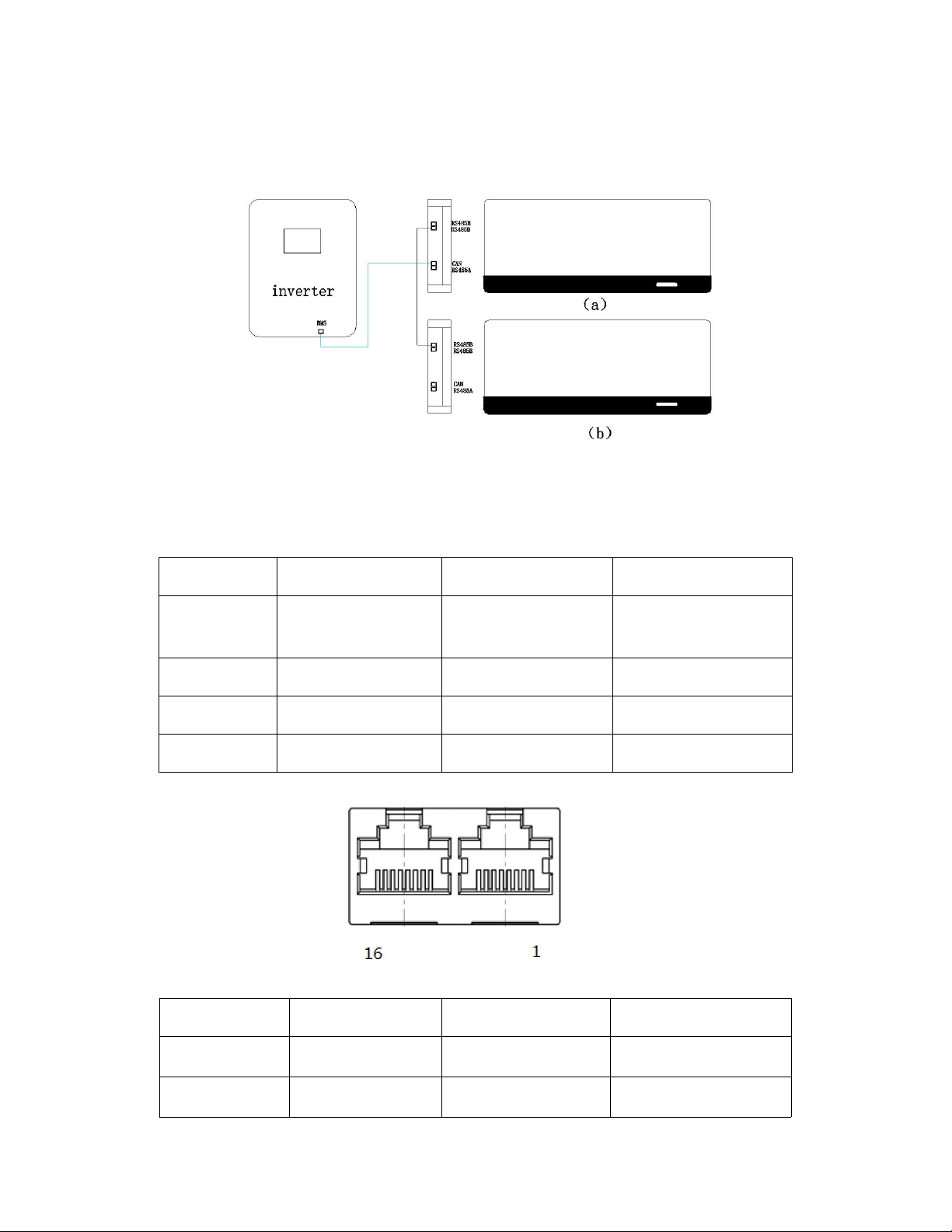
1) Independent communication
When the single machine is used, the battery is set as the host and communicates with the inverter via
RS485A/CANBUS;
- 12 -
2) Parallel communication
When multiple batteries are used in parallel, the batteries are connected in parallel through the RS485B
communication interface; The battery near the inverter is set as the host and communicates with the
inverter via RS485A/CANBUS;
4.7.3 Communication interface definition
1) Definition of RS485A and CAN bus communication port
RS485 A
Definition
CAN
Definition
Pin1,8
RS485_B
Pin 9、10、11、
14、16
NC
Pin2,7
RS485_A
Pin 12
CANH
Pin3,6
GND
Pin 13
CANL
Pin4,5
NC
Pin 15
GND
2) RS485B parallel communication port definition
RS485 B
Definition
RS485 B
Definition
Pin 1、8
RS485-B
Pin 9、16
RS485-B
Pin 2、7
RS485-A
Pin 10、15
RS485-A

- 13 -
Pin 3、6
GND
Pin 11、14
GND
Pin 4、5
NC
Pin 12、13
NC
4.8 Power-on and power-off
Power on: When the battery is off, press on / key for 3 seconds. The LED is activated when the light
flashes from the RUN to the minimum capacity indicator.
Power off: When the battery is active, press on / Key for 3 seconds. The LED light is turned off when
flashing from the minimum capacity indicator to the RUN light.
Machine reset key: press RST key for 6 seconds, reset BMS, and then clear all abnormal states;
press RST key for 3 seconds, with shutdown and startup function;
5. Product responsibility and consulting
1) We shall not be liable for accidents caused by operation violation of this specification and user
manual.
2) If the content of this specification changes due to improved product quality or technical upgrade, we
will not notify us separately; if you want the latest information about the product, please contact us.
3) The shelf life of the product is 5 years after delivery; If there is any quality problem within the specified
scope of operation, we will maintain the products within the warranty period free of charge; If we are
unable to maintain them, we may replace the relevant parts for sustainable use without compromising
performance; Our after-sales service personnel will propose specific maintenance and troubleshooting
methods.
Table of contents
Popular Batteries Pack manuals by other brands


Otto Bock
Otto Bock 757B20 Instructions for use

Simu
Simu AUTOSUN 9014734 instructions

Philips
Philips AquaTrio Important safety information

EnerSys
EnerSys datasafe HX Installation, operation and maintenance instructions

REVOV
REVOV R100 quick start guide

Panasonic
Panasonic CF-VZSU30AU operating instructions


