enphase IQ Battery 5P User manual

To exchange with ROW barcode
1 IQ Battery 5P Quick Install Guide
IQBattery5P
Quick Install Guide
MODEL
IQBATTERY-5P-1P-INT
VERSION 2.0
OCTOBER 2023
Scan the QR code for the
latest Install Guide
2 IQ Battery 5P Quick Install Guide
To install the Enphase IQBattery5P and the wall-mount bracket, read
and follow all warnings and instructions in this guide. Safety warnings
are listed at the end of this guide. These instructions are not meant
to be a complete explanation of how to design and install an energy
storage system. All installations must comply with national and local
codes and standards. Only Enphase certied installers shall install,
troubleshoot, or replace IQBattery5P.
The IQBattery 5P system includes the battery cell pack with
integrated IQMicroinverters and battery management system (BMS).
The system requires IQ Gateway Metered and Communications
Kit 2 for grid-tied operations. The IQGateway Metered measures
PV production, IQBattery 5P charge/discharge power, and home
energy consumption, and it senses when it is optimal to charge or
discharge the battery so that energy is stored when it is abundant
and used when it is scarce.

Contents
What’s in the box 4
Tools/additional items required 5
Unboxing IQBattery5P 7
Mounting the product 8
Plan a location for the IQBatteries 8
Minimum clearance 9
Mounting surface 10
Install the bottom mounting bracket and the top protective
shield 11
Installing IQBattery 5P 16
Prepare to install IQBattery5P
on the bottom mounting bracket 16
Installation of Anchor Clip 21
Wiring 22
Install conduit and eld wiring 22
Control (CTRL) wiring between system components 26
Cable routing and closing the wiring cover 28
Energizing and conguring the system 31
Installing the ID cover 32
Disassembling the IQBattery5P cover 35
Disengaging the Anchor Clip 37
Operation 38
LED overview 38
Operating mode 39
Troubleshooting 40
Shutdown procedure 40
Safety 41
Revision history 43
IQ Battery 5P Quick Install Guide 3

What’s in the box
DESCRIPTION MODEL NUMBER QUANTITY
IQBattery5P B05-T02-INT00-1-2 1
ID cover, two conduit covers B05-CX-0550-O 1
Bottom mounting bracket and top protective shield B05-WB-0543-O 1
M5 Locking screw 2
M4 Grounding screw 2
M5 ID cover grounding screw 2
Quick Install Guide 1
Anchor Clip 2
Wall drill template 2
Cable ties 6
Control (CTRL) connector (one spare, one pre-installed) 2
Control (CTRL) connector with resistor (one spare, one pre-installed) 2
IDcover IQBattery5P
Top
protective
shield
Conduit cover
Conduit cover
Bottom
mounting
bracket
(to be installed
rst on the wall)
M5 Locking screw
Anchor Clip
M4 Grounding screw M5 ID cover grounding screw
Quick Install Guide
IQ8D-BAT Microinverters
Backplate
Wiring cover
DC control switch
button
DC control switch
and LED
Control connector Control connector with resistor
4 IQ Battery 5P Quick Install Guide

Tools/additional
items required
S. NO ITEM NAME QUANTITY SOURCE
1 Conduit up to 32 mm for side entry and up to 19 mm for rear entry As required Provided by installer
2 Conduit ttings or cable glands and tools must be IP55-rated when installing outdoors As required Provided by installer
3 Drill 1 Provided by installer
4 4 mm pilot bit 1 Provided by installer
6 Screwdriver 1 Provided by installer
7 Wrench 1 Provided by installer
8 Socket wrench 1 Provided by installer
9 Torque wrench 1 Provided by installer
10 Level 1 Provided by installer
11 Conductor stripper 1 Provided by installer
12 Stud nder (if required) 1 Provided by installer
13 Copper conductors - 6 mm2to 25 mm2(rated at 90°C) As required Provided by installer
14 Control cable As required Provided by installer
15 Personal protective equipment for handling lithium batteries
as required by local safety standards As required Provided by installer
16 Protective gloves for protection against sharp edges As required Provided by installer
17
M8 lag bolts or screws to install the bottom mounting bracket. Slots are
9.2mm for the wall mount and 11.2 mm (inclined slots) for the pedestal. Check
with a structural engineer and local standards for requirements
Single stud
mounting
(Min. 3)
Dual stud
mounting
(Min. 4)
Provided by installer
18 M6 screws to fasten the top protective shield on the wall. Use
standard screws only (head thickness <5 mm)
Single stud
mounting
(Min. 6)
Dual stud
mounting
(Min. 6)
Provided by installer
19 Washers As required Provided by installer
20 IQBattery5P lifting handles. Includes one left-side and one
right-side lifting handle (SKU: IQBATTERY-HNDL-5) 1Enphase distributor/
provided by installer
IQ Battery 5P Quick Install Guide 5

NOTE: The Enphase IQBattery 5P system requires an internet
connection through the IQGateway Metered. Failure to maintain
an internet connection may have an impact on the warranty. See
enphase.com/warranty for full terms.
The IQBattery 5P is connected to the IQGateway Metered via
Communications Kit 2 and communicates using communication
control cables. The tested and supported control cable make
is Belcom and model is 4302P2254-01. The Enphase PV system
communicates with the IQGateway Metered using power line
communication.
NOTE: The rated energy capacity of the battery is 5.0 kWh.
Install the PV system, IQ Gateway Metered, IQ Relay (as required
by local regulations), and Communications Kit 2 as directed by the
Enphase installation manuals.
The following table lists the product compatibility matrix. PRODUCT
PRODUCT IQ BATTERY P – GRID-TIED
IQ7 Yes
IQ8 Yes
String inverter Yes
String + IQ7/IQ8/M series No
M Series No*
IQ7 + M Series No*
IQ7 + IQ8 No**
AC Battery No
* The IQ Battery 5P must be installed on a separate gateway.
** The IQ Battery 5P can be installed on a gateway either with the
IQ7 or IQ8.
Tools/additional
items required
6 IQ Battery 5P Quick Install Guide
8
Unboxing
IQBattery5P
Risk of injury and equipment damage. The total lifting weight,
with handles attached, is 67.35 kg. Handles must be used while
lifting the battery. Two-person manual lifting is allowed only if
permitted by local laws. Otherwise, use mechanical lifting.
Inspect the packaging and the IQBattery(ies) for any signs of
damage, such as cracks, dents, or electrolyte leaks. Do not install
or use the IQBattery(ies) if it has been dropped or damaged in
any way. If the battery is damaged, contact your distributor for a
replacement.
Before you unbox IQBattery5P, check the “Energize By” label on
the shipping box to verify that the IQBattery(ies) will be installed by
the date shown. If the date has passed, contact your distributor for
next steps.
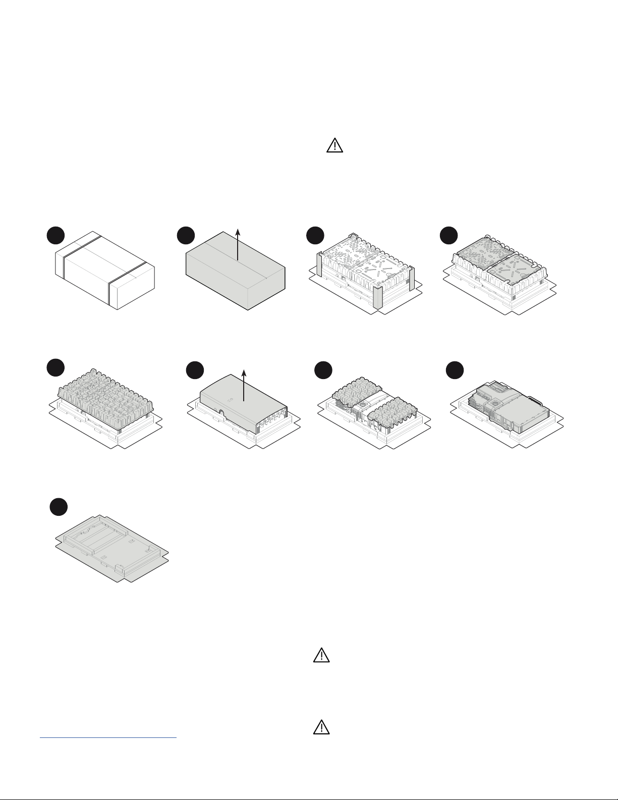
Remove the upper packaging cover and follow the steps, as shown
in the following image:
Do not lift the IQ Battery 5P using microinverters or the
plastic behind the microinverters. This may damage the unit
permanently.
Always use handles to lift the IQ Battery 5P.
Do not lift the packaging with the battery inside after the
plastic straps are cut.
Remove the plastic
straps
Remove the exterior
cardboard box lid
Remove the four corner
guards
Remove the
IQBattery5P cover
Remove the two paper
trays
Remove the IQBattery5P
using lifting handles*
Recycle packaging according
to local guidelines
Remove the top protective shield
and bottom mounting bracket
1234
910
11
1234
78
9
Remove the
paper trays
56
*NOTE: To install handles on the IQ Battery 5P, follow steps 1 to 3
in Installing IQBattery 5P on page 16.
5
IQ Battery 5P Quick Install Guide 7

Plan a location for
the IQBatteries
Mounting the product
Section A
• The IQBattery 5P housing is IP55-rated and can be installed indoors or outdoors.
L/N terminal blocks accept copper conductors of size 6 mm2to 25 mm2.
• Field Ground terminal blocks accept copper conductors of size 0.5 mm2to 10 mm2
• Make sure the installed location can sustain the total weight of the IQBatteries and mounting bracket.
The total weight for IQBattery5P, including the IQBattery 5P unit, cover, and wall-mount bracket, is
78.9kg. The wall must contain blocked studs that can bear the battery weight or can be of masonry or
other suitable structure.
• Make sure there are no pipes or electrical wires in the wall where you plan to drill.
• Follow local standards: Choose a well-ventilated location where the ambient temperature and humidity
are within −20°C to 55°C and 5% to 95% relative humidity, non-condensing, out of direct sunlight. The
optimum ambient temperature range for installation location is 0ºC to 30ºC. Provide smoke alarms in the
residence in accordance with building, re, and installation codes.
• This product must not be installed at altitudes above 2500 m.
• Follow all local standards and regulations set forth by the
Distributed Network Service Provider (DNSP/
DNO).
• Up to four IQBattery5P units can be daisy-chained on a single branch circuit.
• The maximum conductor size compatible with IQ Battery 5P is 25 mm
2
, and the maximum breaker
rating with this conductor size is 80 A Type B. Use a 20 A Type B breaker for one IQ Battery 5P and
Max. 80 A Type B breakers for four daisy-chained batteries.
• Follow all local standards and regulations while selecting the AC breaker.
• Consider the dimensions of the IQBatteries, easy access, height, and length of cable when selecting
the location.
• Select a location where you can interconnect IQBattery 5P to the IQ Gateway Metered,
Communications Kit 2, and IQ Relay (as required by the local laws).
Max 4
2500m
-
+
20°C
55°C
78.9 Kg
WARNING! IQ Battery 5P devices should NOT be installed on a ammable surface. When installing
on a wooden wall, it is suggested to use a ame-inhibition plate between the wooden wall and IQ
Battery 5P. Consult the regional building regulations for any additional requirements.
8 IQ Battery 5P Quick Install Guide
Section A - Mounting the product
Minimum clearance
The mounting instructions that follow are for the included wall-mount
bracket only. If you wish to install IQ Battery 5P in a oor-mount
conguration, order the pedestal accessory (Order code: B05-PM-
0550-O) and refer to the oor-mount instructions that come with that
product.
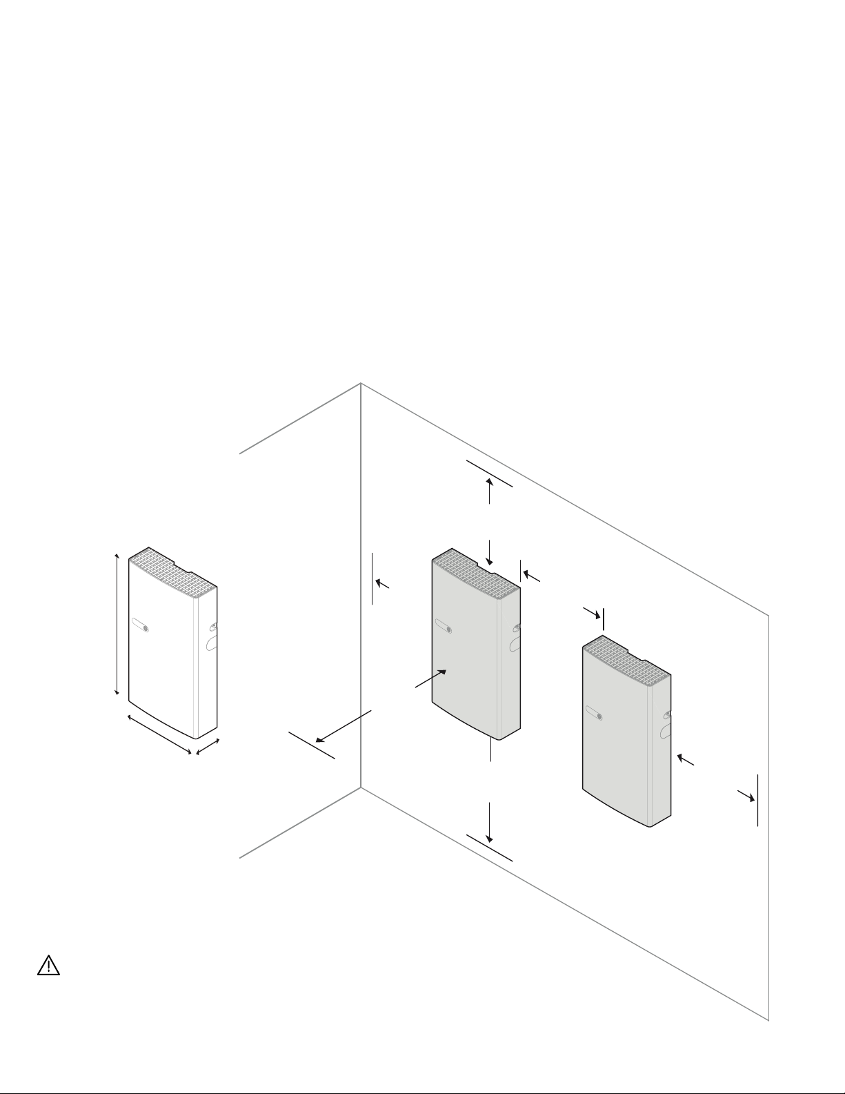
This product must be installed with clearance at the left,
right, top, bottom, and front of the product, as shown in the gure.
Keep IQBattery 5P away from falling or moving objects,
including motor vehicles.
*NOTE: For IQ Batteries mounted side-by-side, the minimum
distance between the covers of two units should be 76 mm.
Installation handles cannot be used for clearance less than
150 mm, and installers need to consider adjusting the distance
between batteries based on cable bending radius and local
regulations.
900 mm**
150 mm
150 mm
150 mm 150 mm
150 mm*
550 mm
980 mm
188 mm
**NOTE: The minimum clearance to be maintained in front of
the batteries is 250 mm.
If mounted in the path of a motor vehicle, Enphase
recommends a minimum mounting height of 900 mm above
the oor.
Step 1
IQ Battery 5P Quick Install Guide 9

Section A - Mounting the product
Mounting surface
NOTE: If the variation of the atness is more than 2 mm, the battery
might not properly sit on the bottom mounting bracket
through
keyholes. Use spacers or unistruts if the variation is more than 2 mm.
max. -5°
max. +5°
≤ 2 mm
1
2
Select a location where the tilt
from vertical is less than 5°.
Make sure the mounting surface
atness is within 2 mm between
boundary lines.
Step 2
10 IQ Battery 5P Quick Install Guide

Section A - Mounting the product
Bottom mounting bracket
Inclined slots for
pedestal assembly
Mounting slots
The bottom mounting bracket carries the weight of the IQ Battery 5P,
and the top protective shield covers the back of the IQ Battery 5P.
Risk of injury and equipment damage. Do not mount an
IQBattery5P on a bracket that is not properly mounted.
• Use a minimum of six M6 screws for mounting the top protective
shield to the wall. Use standard screws only (head thickness <5
mm).
• Use M8 screws/lag bolts (9.2 mm) with a washer (or masonry
attachments for masonry wall) for each slot to attach the
bottom mounting bracket.
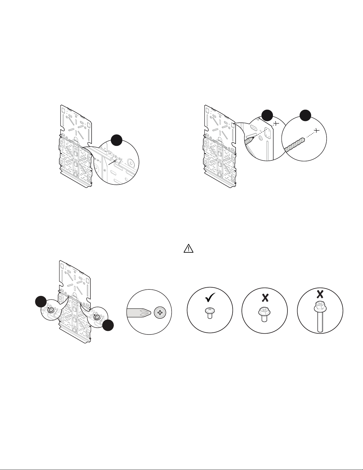
Install the bottom mounting bracket
and the top protective shield
522 mm
461 mm
Two embosses with indentation
marks provide exibility to
installers to x the top protective
shield
10 wall-mounting hole
options, marked,“P”,
“Q”, and “E”
Two anges for connecting
the top protective shield to the
bottom mounting bracket
Top protective shield
L1 L4L2 L3
534 mm
513 mm
Q4 P4
P1 Q1 Q3 P3
U1 U2 U3 U4
P2 Q2
E1
E2
The keyholes are to mount the base
unit of IQ Battery 5P to the bottom
mounting bracket. Do not use these
keyhole slots for mounting the
bottom mounting bracket to the wall.
Step 3
IQ Battery 5P Quick Install Guide 11

Section A - Mounting the product
Starting at the installation position closest to the power source,
mark a level line on the wall as a guide.
Install the bottom mounting bracket as per the following instructions.
Make sure
the bottom mounting bracket
is rmly attached to the wall.
Multiple risks. Make sure not to drill into or attach to electric
wiring or pipes in the wall.
For the ease of marking all the required drilling points, a dedicated
drill template is provided along with the packaging. Depending on
the type of installation wall, choose the instructions stated on the
template.
12
43
12 IQ Battery 5P Quick Install Guide
450 mm
5a
Section A - Mounting the product
5b
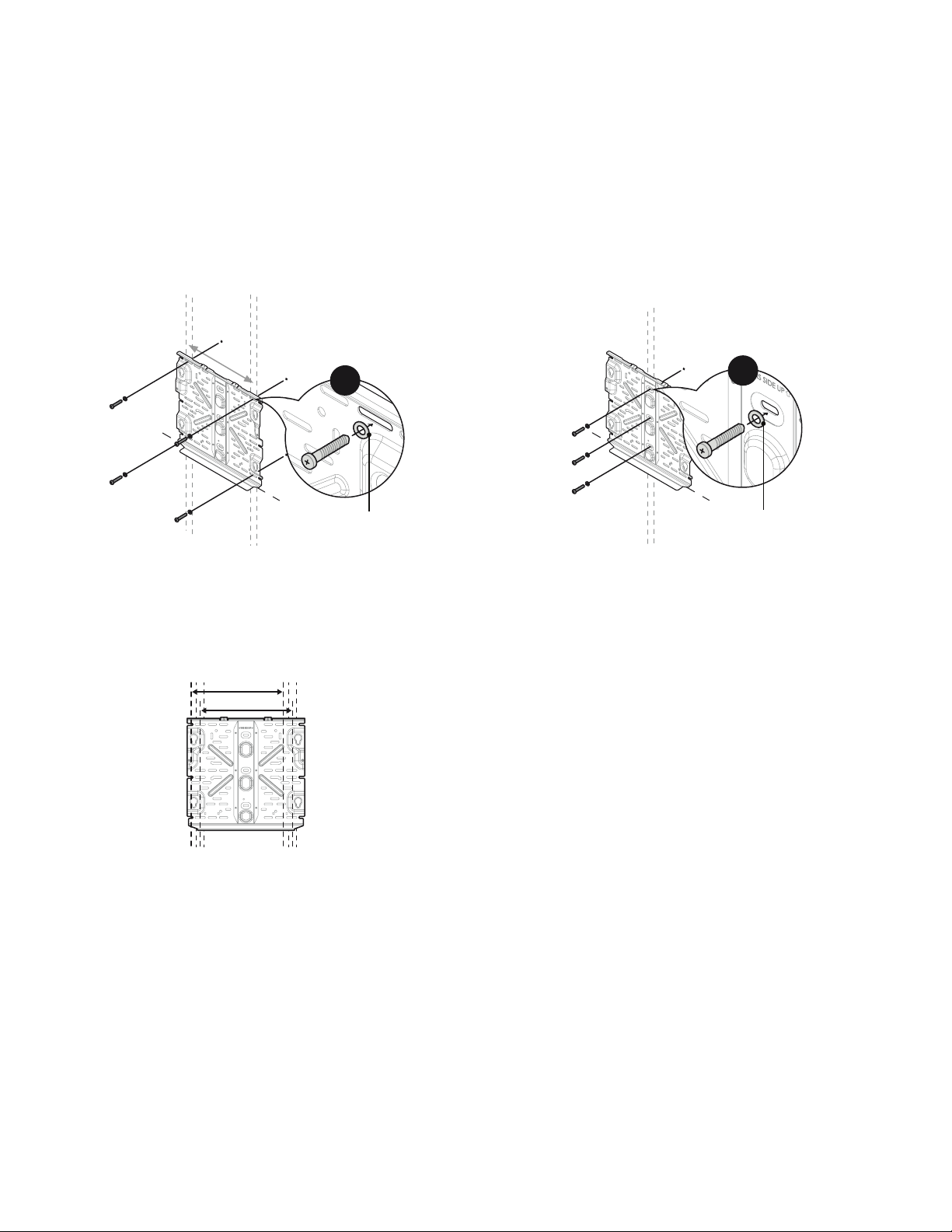
The bottom mounting bracket can accommodate a slight oset in stud
positioning with respect to the battery unit with pre-drilled holes/
slots, as shown in the image.
Position the bottom mounting bracket on the wall and fasten
it using the mounting slots.
Use a minimum of four M8 screws or lag bolts (symmetrically
distributed) for dual stud mounting.
Tighten all screws to the
manufacturer’s specied torque values.
Position the bottom mounting bracket on the wall and fasten it using
the mounting slots.
Use a minimum of three M8 screws or lag bolts (on the centerline)
for single stud mounting.
Tighten all screws to the manufacturer’s
specied torque values.
Mounting on multiple vertical studs (450 mm stud spacing) Mounting on a single vertical stud
450 mm
450 mm
Washer
Washer
NOTE: Any one of the above mounting methods can be used for
mounting a battery on a masonry wall.
IQ Battery 5P Quick Install Guide 13
Section A - Mounting the product
NOTE: The top protective shield is not a structural part and need
not always be mounted to the studs. It can be fastened to the
supporting wall with the pre-drilled holes if the studs are not
aligned.
Two M4 grounding screws
Position the ange of the top protective shield with the ange of the
bottom mounting bracket and align the screw slot/hole.
Partially tighten the top protective shield to the bottom mounting
bracket at the ground contact ange.
Multiple risks. Make sure not to drill into or attach to electric
wiring or pipes in the wall.
6
7 8
9a
9b
9a
9b
Mark holes on the wall. Then remove the top protective shield
and drill holes in the wall.
14 IQ Battery 5P Quick Install Guide

Section A - Mounting the product
Fasten the top protective shield using the mounting holes. Use
a minimum of six M6 screws for dual stud mounting to fasten the
top protective shield to the wall. Use standard screws only (head
thickness <5 mm).
Finally, fully tighten the M4 grounding screws between the two
shields (torque to 1.5 N m).
Fasten the top protective shield using the mounting holes. Use a
minimum of six M6 screws for single stud mounting to fasten the
top protective shield to the wall. Use standard screws only (head
thickness <5 mm).
Finally, fully tighten the M4 grounding screws (torque to 1.5 N m).
For mounting on multiple vertical studs with 600 mm stud spacing
or on an uneven wall, use unistrut.
10a 10b
NOTE: Ensure to always
fasten this screw.
NOTE: Ensure to always
fasten this screw.
Mounting on multiple vertical studs Mounting on a single vertical stud
Unistrut
NOTE: Use an electric drive; do not use impact drives or impact drills
to tighten the grounding screws.
IQ Battery 5P Quick Install Guide 15

Remove the ID cover from the packaging and keep it aside. Use
the reusable lifting handles (sold separately) and check that the
plungers on the handle are extended and ready to engage into the
IQBattery5P slots.
Align the left handle on the left side of IQBattery5P, insert it into
the slots and slide it toward the top of the IQBattery5P enclosure
until the plunger locks into place. Check that the handle is secure.
Repeat on the other side with the right handle.
Risk of injury and equipment damage. The total lifting weight
with handles attached is 67.35 kg; lift according to local
law. Handles must be used while lifting the battery. Two-
person manual lifting is allowed only if permitted by local law.
Otherwise, use mechanical lifting.
1 2 3
Section B
Installing IQBattery 5P
Two people together must lift the IQBattery5P unit from
the packaging using the handles and place it in an upright
position on the oor, taking support of the backplate or
wiring cover.
Lift IQBattery5P from the packaging using the handles and
make sure the battery’s front side is facing towards
you.
Do not lift the IQ Battery 5P using microinverters or the
plastic behind the microinverters. This may damage the
unit permanently.
NOTE: Complete all the above steps before installing IQ Battery 5P
on the wall. 4
Prepare to install IQBattery5P
on the bottom mounting bracket
16 IQ Battery 5P Quick Install Guide
Section B - Installing IQBattery 5P
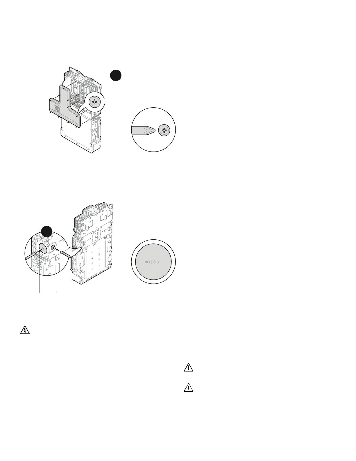
Drill the appropriate cutout on either the back or side of the unit
or both based on congurations. The rear entry can support the
conduit with a diameter of 13 mm to 19 mm while the side entry can
support the conduit with a diameter of 13 mm to 32 mm. L and N
terminals can accept a maximum cable size of 25 mm2. The ground
terminal can accept a maximum cable size of 10 mm2.
Install cable glands on the sides where cable entry is planned before
mounting the units on the wall.
6
Open the front wiring cover by unfastening the 11 captive screws
from the wiring cover. Use a screwdriver or an electric drive; do not
use impact drives/impact drills.
NOTE: Remove the top screw at the last to avoid damage to the
wiring cover.
5
11x
6
Drill to appropriate cutout
Captive screws
torque to 1.5 N m
Drill here
D
R
I
L
L
H
E
R
E
Risk of electric shock. The DC control switch must be OFF
before performing this step.
NOTE:
Before mounting the unit on the wall, drill the appropriate
cutout. Drilling the cut-outs after mounting the unit to the wall can
lead to internal component damage, which is not covered by the
warranty.
Ensure that the drilling machine does not touch any internal
components or walls.
Clean the debris from inside the battery unit after drilling.
IQ Battery 5P Quick Install Guide 17
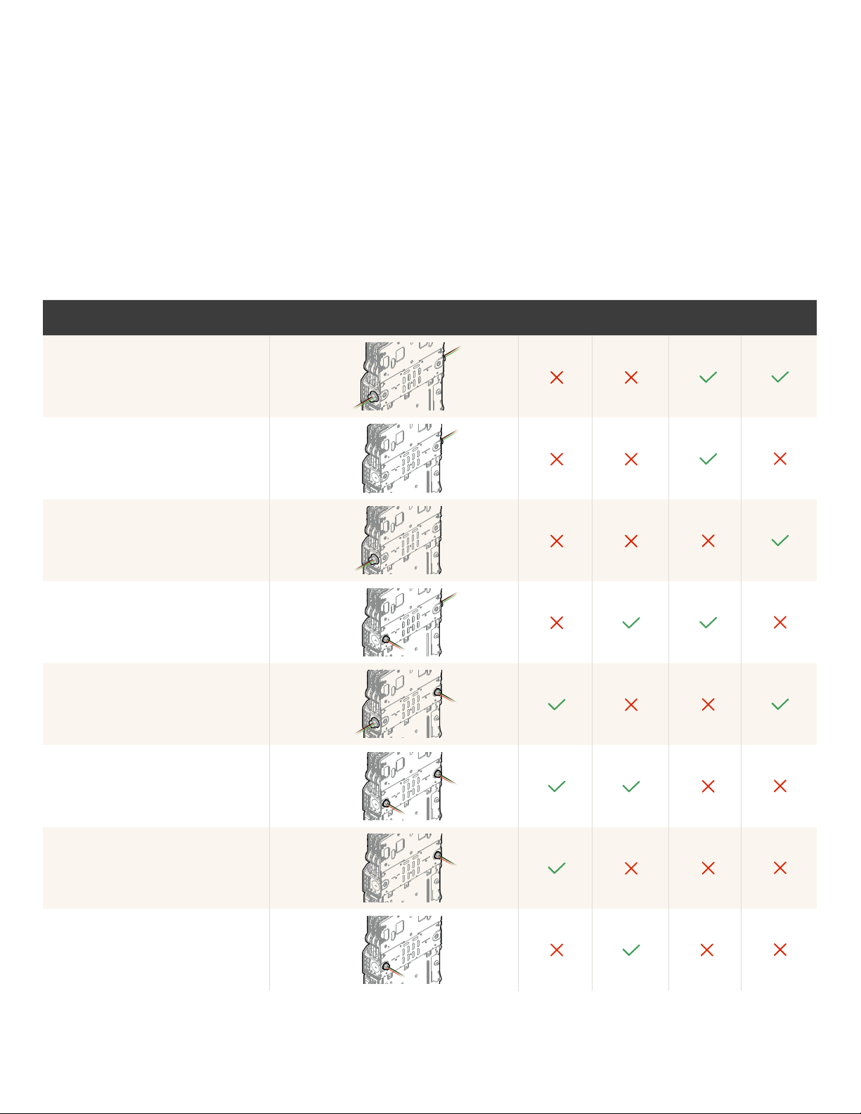
Section B - Installing IQBattery5P
IQBattery5P can have the eld cable entry from the back, left,
or right side. Finalize the side from where the eld cable enters and
leaves IQBattery5P. Use the following table to decide the cutout for
all the units.
NAME BACK VIEW LEFT-BACK
CONDUIT
RIGHT-BACK
CONDUIT
LEFT SIDE
CONDUIT
RIGHT SIDE
CONDUIT
Both side conduit
Only left side conduit*
Only right side conduit*
Left side conduit and right-back conduit
Left-back conduit and right side conduit
Both back conduit
Only left-back conduit*
Only right-back conduit*
Both Side Conduit
Only Left Side Conduit
Only Right Side Conduit
Left Side Conduit - Right Back Conduit
Left Back Conduit - Right Side Conduit
Both Back Conduit
Only Left Back Conduit
Only Right Back Conduit
* One-side conduit conguration is supported only if the system has one IQBattery5P or for the unit last in the daisy
chain farthest from the Communications Kit 2.
NOTE: The rear entry can support the conduit with a diameter of
13 mm to 19 mm, while the side entry can support a conduit with a
diameter of 13 mm to 19 mm. Follow manufacturer-recommended
instructions for conduit installation.
18
IQ Battery 5P Quick Install Guide

Section B - Installing IQBattery 5P
Bring the IQBattery5P unit to the already mounted
bottom mounting bracket.
To remove the installation handles, pull the plunger outward to
unlock them. Then, slide the handle down and pull it away from the
unit to remove it.
Hold IQBattery5P straight, align, and insert four mount bolts on the
battery unit into the bottom mounting bracket keyholes and slide it
down.
NOTE: Use lift assist to avoid any mishap during lifting.
8
9 10 11
7
IQ Battery 5P Quick Install Guide 19

Section B - Installing IQBattery 5P
12
The vent or drain holes provided at the back of the unit serve
the dual purpose of natural ventilation and condensation
drainage. Blocking these holes can aect the functionality
of the product.
Secure the battery unit on the bottom mounting
bracket using two M5 locking screws.
This is required to comply with seismic requirements.
Vents or drain holes
2x
Two M5 Locking screws
torque to 5.6 N m
12
NOTE: Use a screwdriver or electric drive; do not use
impact drives or impact drills while tightening locking
screws
NOTE: It is recommended to use a screwdriver
extension bit to reach the screw head.
20 IQ Battery 5P Quick Install Guide
Other manuals for IQ Battery 5P
3
Table of contents
Other enphase Batteries Pack manuals


