Focal Point P23E Guide

INSTALLATION AAND UUSER IINSTRUCTIONS
All iinstructions mmust bbehhanded ttouuser ffor ssafekeeping
Revision B - 06/06
Country(s) of destination - GB/IE
MONET aand TTRINITY
ELECTRIC WWALL HHEATERS
MODEL ::PP23E
Focal Point Fires plc, Christchurch, Dorset BH23 2BT
Tel: 01202 499330 Fax: 01202 499326
www.focalpointfires.co.uk
e-mail: [email protected]

MONET ((P23E)
Fig 1 Dimensions Monet shown
TRINITY ((P23E)

CONTENTS
PRELIMINARY NNOTES
The Monet and Trinity Electric Wall Heaters provide convected heating in conjunction with a visual fuel effect
display. The Trinity differs only in respect of the design of the decorative front frame.
The appliance is designed for indoor use, and can be simply wall mounted in the majority of wall positions antic-
ipated. It can can be located in any household room, with the exception of bathrooms.
Read all of the instructions before commencing installation. Retain for future reference and pass on as necessary
to subsequent owners of the appliance.
DO NOT use this appliance immediately below a fixed socket outlet.
DO NOT use this appliance in the immediate vicinity of a bath, shower, swimming pool or other area where
water/moisture could present a hazard.
CAUTION: TThis aappliance mmust nnot bbeuused iincconjunction wwith aany ttimer, pprogrammer oortthermal ccontrol, oor
any oother ddevice tthat wwill sswitch oontthe aappliance aautomatically, aasaaffire rrisk mmay ooccur iiftthe hheaters aare aacci-
dentally ccovered oorddisplaced.
Note: TThe hheater ooutlet iisllocated oontthe ttop ssurface bbehind tthe ffront fframe.
Do not allow the heater to be covered as this may cause overheating. Additionally, DO NOT place any items on
top of this appliance. The appliance must not be placed near curtains or similar material. A clearance space of
at least 500mm should be allowed in front of the appliance.
The eelectrical ssocket tthat tthe aappliance uuses MMUST bbeeeasily aaccessible. DDonnot rroute tthe ssupply ccord ddirectly
over ooraabove tthe hheater uunit. IIftthe ccord iisddamaged, iitmmust bberreplaced bbyaasservice aagent oorccompetent pper-
son.
APPLIANCE DDATA
ELECTRICAL INSTALLATION REQUIREMENTS
The appliance is designed to be wall mounted using the brackets and fixings provided.
DDOONNOOTTRREECCEESSSSAANNYYPPAARRTTOOFFTTHHEEAAPPPPIIAANNCCEE..
The appliance is supplied with a pre-wired three pin BS1363 plug (13 Amp fuse rated), and 2 metre
cable. A standard switched outlet/wall socket, (including earth provision), must therefore be located
within this distance, and be easily accessible in order to isolate the supply for maintenance and clean-
ing. This socket
mmuussttnnoott
be mounted behind or above the appliance.
IIMMPPOORRTTAANNTT::TTHHIISSAAPPPPLLIIAANNCCEEMMUUSSTTBBEEEEAARRTTHHEEDD..
1
Section Contents Page No.
1.0 Preliminary Notes 1
2.0 Appliance Data/Specifications 1
3.0 Electrical Installation Requirements 1
4.0 Site Requirements 2
5.0 Clearances to Combustible Materials 2
6.0 Unpacking the Appliance 3
7.0 Component Checklist 3
1.0
Section Contents Page No.
8.0 Preparing the Appliance 3
9.0 Fixing the Appliance 4
10.0 Operating the Appliance 5
11.0 Safety Cut-Out System 5
12.0 Maintenance - Lamp Replacement 6
13.0 Cleaning 6
14.0 Servicing 6
Weight ((kg): 10.0 kg
Dimensions ((mm): H 585 x W 500 x D 133
Voltage ((Volts): 230-240V a.c. 50Hz
Heating EElements: 2 x 900/1000 Watts
Supply CCord: 2 metres
Supply PPlug: BS 1363, 13A Fused
Location: Indoor Use
Lighting: 1 x 60W Amber B.C. Bulb
2.0
3.0

SITE RREQUIREMENTS
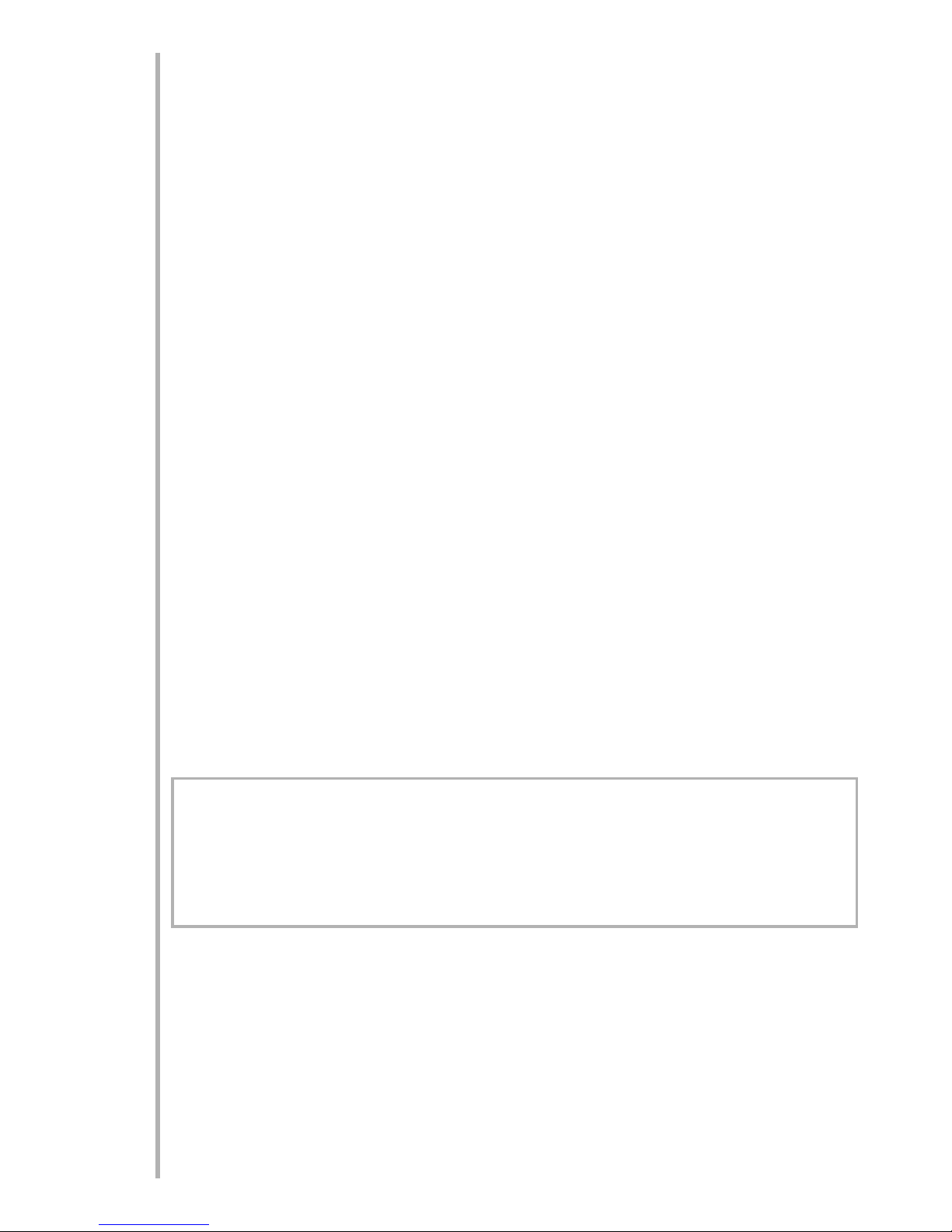
The appliances are designed to be wall mounted via the brackets on the rear panel with the fixings
provided. The wall should be relatively flat and not interfere with any of the ventilation slots in the rear
panel.
The wall must be structurally sound and of a material capable of withstanding moderate heat. Finished
plaster, conventional wallpaper, dry-lined plaster board are examples of suitable materials. Materials
such as “flock blown vinyl”, embossed paper and cloth wall coverings which are sensitive to even
small amounts of heat should be avoided, as some discolouration may occur.
It should be noted that the appliance creates warm convected air currents. These currents move heat
from the room surroundings to, and up the wall surfaces adjacent to the heater.
Installing the heater next to these types of wall coverings or operating the heater where impurities in
the air, (such as tobacco smoke) exist, may slightly discolour wall finishing.
If the appliance is to be mounted on a dry lined or timber framed construction then the integrity and
ability of the wall to carry the weight of the appliance must be confirmed. It is important in these cir-
cumstances that any vapour barrier and/or structural members of the house frame are not damaged.
If you are unsure of the ability of the wall to carry the weight and/or which type of wall fixing to use,
you should take professional advice and obtain the correct fixings. Alternatively, find a more suitable
wall location.
DDOONNOOTT-mount on a ceiling or floor.
-recess any part of the appliance into the wall.
-site any electrical equipment e.g. plasma screen TV sets etc,
on the wall above the appliance.
- site in a position where curtains or drapes could cover the appliance.
-site in a position where other soft materials could cover e.g. below a coat rack.
-site behind an opening door where mechanical impact/damage could occur.
-site where the supply cable would become a trip hazard.
-sit, stand or forcefully pull on the appliance.
-obstruct, cover or force items into the openings.
-use the heater to dry clothes.
- site/use in an outdoor location(s).
-run the supply cable under carpets.
CLEARANCES TTOCCOMBUSTIBLE MMATERIALS
It is important that the following clearances are maintained from the appliance to combustible materials. These
clearances are dependant on the mounting location as defined below:
a) WWall MMounted:
The minimum distance from the top of the appliance to a ceiling is 500mm.
The minimum distance to the sides of the appliance is 100mm.
The minimum distance to the front of the applaince is 500mm.
The appliance can be wall mounted at floor level, providing it does not stand on a carpet or similar material.
Allow clearance to carpets of 30mm.
A shelf may me mounted above the appliance provided it meets the requirements for shelfs as detailed in b)
below.
b) FFloor/Fireplace MMounted:
If mounted into a fireplace surround, ensure that the minimum clearance distances to mantles and/or any
shelves fitted above the appliance are as follows:
When iinstalled wwith aaccombustible ffire ssurround, tthe aability ooftthe ssurround ttowwithstand pprolonged mmoderate
heat mmust bbeaassured.
2
4.0
5.0
Shelf DDepth Minimum SShelf DDistance
(measured from top of appliance)
2” or (50mm) 11.5 “ or (290mm)
6” or (152mm) 15.4 “ or (390mm)

UNPACKING TTHE AAPPLIANCE
Caution: TThis aappliance iishheavy. AAlways sseek aassistance wwhilst uunpacking aand/or dduring iinstallation.
Read
all
the instructions before continuing to unpack or install this appliance. Carefully remove the appliance
from its packaging and lay on the floor with it`s back surface downward.
Note: DO NOT stand the appliance on its front frame as this may cause distortion.
Check that the remaining packaging contents correlate with the component checklist below. Please dispose of
all packaging with care at your local recycling centre.
COMPONENT CCHECKLIST
QUANTITY DESCRIPTION
1Fire Appliance and Decorative Frame
1 Bag of Decorative Pebbles
1 Instruction Booklet
3 37mm long round head screws
3 Wall plugs
1 Wall Mounting Template
2 Decorative frame edge sets and attachment magnets (
Trinity MModel OOnly))
PREPARING TTHE AAPPLIANCE
DO NNOT cconnect tthe aappliance ttotthe ssupply aattthis sstage.
1. Carefully remove the front decorative frame from the main casing by unscrewing and
removing the 2 lower M6 fixing bolts, (2 located on either side), as shown
in Fig 2.
Lift the frame vertically upwards to clear the upper two fixing bolts and pull
gently forwards to release from the main case assembly.
Now remove the 2 x No 8 Phillips self tap-
ping screws, retaining the lower lamp cover
plate, as shown in Fig 3, and remove the
cover plate.
3. Carefully “ease” the white fuel bed from the appliance.
This allows access to the lower fixing position located at the back of
the main case assembly. See Fig 4.
3
6.0
7.0
Fig 2
Fig 3
No 8 fixing
screws
Lamp cover
plate
Fig 4
Lower fixing
position
Lower
Fixings
Upper
Fixings
8.0

FIXING TTHE AAPPLIANCE
A) MMarking PPositions:
Having selected the final mounting position for the appliance, taking into account the site requirements as
detailed in section 4, the heater can now be fixed to the wall.
There are three fixing positions, two upper “hanging” positions”, and one lower position on the backpanel locat-
ed behind the fuel bed. Refer to Fig 4 for details.
A template is provided to aid location of fixings. Use a spirit level to ensure that the template is level. This ensures
that both upper and lower fixing positions are horizontally aligned.
Using the template in the required position on the wall, “mark through” the template and onto the wall at the
three mounting locations designated “P23E” for this particular appliance. Now remove the template.
B) WWall FFixings:
If the appliance is to be mounted on the inner leaf of a conventional cavity wall or a solid wall, drill three holes
using a 7mm masonry bit.
Insert the wall-plugs provided. If the appliance is to be mounted on a dry lined wall or timber framed construc-
tion, then special cavity screw fixings will be required, that are not supplied with this product. Insert 2 x 37mm
long fixing screws into the upper two wall-plugs, taking care to leave the screws protruding approximately 6mm
from the wall.
The appliance can now be “hung” onto the two upper wall fixings, ensuring that the heads of the screws go
through the keyhole shaped holes, and then drop down into the slot.
Ensure that the lower rear panel fixing hole aligns with the wall plug, and then insert 1 x 37mm long fixing screw
and fully tighten.
Finally fully tighten the two upper fixing screws, through the two panel acess holes at the front of the appliance.
C) RRe-AAssembly oofAAppliance:
Note: re-assembly is the reverse of disassembly as described in section 8.0
1. Refit the fuel bed, ensuring that the lamp spinner is free to rotate.
2. Refit the lower lamp cover plate, firstly inserting the bottom edge behind the firebox lip. Secure with the two
screws previously removed.
3. Reattach the front decorative frame by hanging onto the two upper fixing bolts, and reinserting the two lower
fixing bolts through the lower fixing brackets. Retighten the two lower fixing bolts.
Note: For Trinity models either the chrome or brass decorative trim pieces can be attached. Use the the supplied
magnets equally spaced along the rear face of each trim section. Fit both side sections firstly, followed by the
top and bottom sections.
Finally, peel off any remaining protective plastic coatings on the front frame, curved backpanel and the plastic
fuel bed.
D) PPlacement oofPPebbles:
Unpack the pebbles and arrange them over the fuel bed. The final
pebble arrangement can only be done later when the lamp is
switched on and light shines up through the transparent cover.
The ideal pebble layout is shown in the photograph on the right.
4
9.0

OPERATING TTHE AAPPLIANCE
Read AAll IInstructions BBefore UUse
Check that the heater outlet grille, mounted at the top of the appliance, is not covered or obstructed in any way,
and ensure the power to the fire is switched on. The appliance is controlled using four switches mounted at the
right hand side towards the top.
The first switch towards the front, marked ((0I), controls the main power to the appliance and switches on the
visual light display. This feature can be used independently of the heating features.
The next switch marked ((*)operates the fan blower without heat, and can be used for cool air circulation.
However for this feature, the main power switch (0I), must also be in the “on” position.
The next switch with a “single bar” marked ((I) operates the low heat, (1kW), setting.
The switch with “two single bars” marked ((II), operates the high heat, (2kW) setting.
To operate the fire in any of the above modes, the left hand switch marked ((OI) must be switched to the “on”
position.
To operate the fire, the first switch must be turned on firstly, followed by the second switch to start the blower,
if required. To obtain heat from the appliance, the I switch must then be operated for LOW heat, followed by
the II switch for the HIGH heat setting.
The aappliance ccan bbesswitched ooff aataany ttime, iirrespective ooftthe pparticular mmode sselected, bbyssimply sswitch-
ing tthe ffirst sswitch mmarked ((OI) ttotthe ““off” pposition.
It iisaalso rrecommended ttouunplug tthe ppower ssupply ccable aattthe ssupply ooutlet wwhen nnot iinuuse.
SAFETY CCUT-OOUT SSYSTEM
This appliance has a safety cut-out system fitted which will activate if the air inlets or heater outlets are obstruct-
ed. For safety reasons the fire WILL NNOT switch on again automatically.
NOTE: TThe vvisual llight eeffect wwill rremain ooperational iiftthe ccut-oout iisaactivated, oonly tthe ffan hheater eelements aare
prevented ffrom ooperating.
The ffollowing pprocedure mmust bbeccarried oout bbefore tthe ffire ccan bbeooperated aagain:
1. Unplug the power supply cable at tthe ooutlet ssocket aand pplace aall sswitches ttoooff aattthe aappliance.
2.Leave the fire OFF for a period of not less than 10 minutes, ensuring any obstructions are removed.
3. Plug in the power supply cable at tthe ooutlet ssocket, aand tthen sswitch oonaattthe aappliance.
If the appliance fails to operate correctly, repeat the above procedure.
If an attempt to switch on is made before the safety cut-out has reset, the heaters may cut-out for a further peri-
od of time. If the sequence has been followed correctly and the heaters still fail to function, check the power
supply cable plug is plugged in at the outlet socket. If this is not the cause, call an electrician.
5
11.0
10.0

MAINTENANCE
ALWAYS DDISCONNECT TTHE AAPPLIANCE AATTTHE SSUPPLY OOUTLET SOCKET BBEFORE UUNDERTAKING AANY
MAINTENANCE.
Excluding the lamp and fuse, use only genuine spare parts available from your supplier. Replacement lamps must
be of the same wattage and specification as those stated in Section 2.0 Appliance Data/Specifications.
Replacing tthe LLight BBulb.
1. Switch off at the appliance, and then disconnect the plug
from the outlet socket.
2. Remove the decorative front frame, and the lower lamp
cover plate (2 x screws), as described in section 8.0 to gain
access to the bulb. Note: the fuel bed can be removed if nec-
essary to aid replacement.
3. The bulb has a conventional bayonet fitting. Remove and
replace with the new bulb (see Fig 5 opposite).
4. Reposition the lower lamp cover plate and replace the two No 8 Phillips screws, and tighten fully.
5. Reposition the decorative front frame and retighten the two lower frame fixing bolts.
6. Reconnect electrical supply and check for correct operation of the lamp and spinner assembly.
CLEANING
ALWAYS DDISCONNECT TTHE AAPPLIANCE AATTTHE SSUPPLY OOUTLET SOCKET BBEFORE UUNDERTAKING AANY
CLEANING.
There are no specific requirements for care, other than regular cleaning of the general appliance. A wipe with a
dry cloth is normally sufficient.
DO NOT use abrasive cleaners as they can damage the finish.
Stainless steel parts may be cleaned using an appropriate metal cleaner or baby oil. Test on a hidden part of the
stainless steel before cleaning. Clean only in the direction of the grain.
SERVICING
There aare nnoiinternal uuser sserviceable pparts.
Check regularly for security of wall fixings as appropriate. Also check security of supply cable and connections.
If the supply cable becomes damaged, it must be replaced by a service agent or competent person, such as a
qualified electrician.
The wires in the cable are coloured in accordance with the following code:
LIVE - Brown
NEUTRAL - Blue
EARTH - Green/Yellow
Refer to Section 2.0, Appliance Data for fuse specification. Excluding fuses and lamps , use only genuine manu-
facturers spare parts available from your supplier.
6
13.0
14.0
12.0
Fig 5
As our policy is one of continuous improvement and development, we hope therefore you will understand
we must retain the right to amend details and/or specifications without prior notice.
Waste electrical products should not be disposed of with household waste. Please recycle where facilities
exist. Check with your local authority or retailer for recycling advice
DO005705/0
Table of contents
Other Focal Point Electric Heater manuals