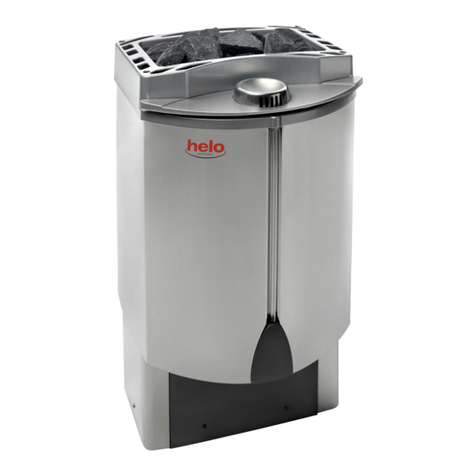
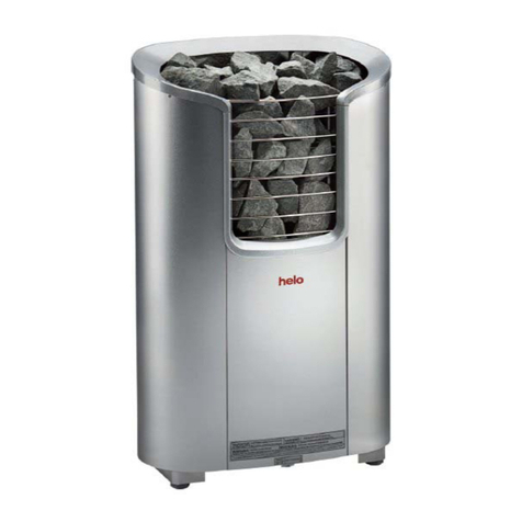
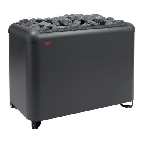
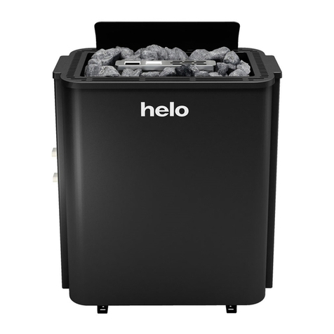
Helo Roxx Premium User manual

ELECTRIC SAUNA HEATER:
1107 –60 –040517
1107 –90 –040517
230V –240V 1N~ / 2~
230V 3~
400V –415V 3N~
CONTROL PANEL:
1601 –31 (RA –31) Trend)
1601 –33 (RA –33) Premium Wifi
314 SKLT 72-3 A
Installation and User Manual HELO Roxx Premium
REWARD YOURSELF

Contents
1.1 Check before taking a sauna bath 3
1.2 Sauna room 3
1.3 Operation of the sauna heater controls 3
1.4 Operation of the sauna heater controls 3
2. Preparing for sauna heater installation 4
2.1 Installation 4
2.2. Various stages of the installation 5
2.2 Installing the sensor near a supply air vent 6
2.3 Ceiling installation of the sensor 6
2.4 Installing the Extra NTC sensor 6
2.5 Sauna heater safety clearances 6
2.6 Connection of the sauna heater to the mains 8
2.7 Electric heating toggle 8
2.8 Locating the connecting box for the connection cable in the sauna room 9
2.9 LocatRemote controlling 9
2.10 Wiring diagram 10
2.11 Recommended sauna room ventilation 11
2.12 Heating the sauna 11
2.13 Sauna heater stones 12
2.14 If the sauna heater will not heat up 12
2.15 Door switch 13
2.16 Principle image when RA 33 Premium is used as control panel 14
2.17 BWT technology in a Roxx Premium heater 15
3. Helo Roxx Premium spare part list 15
4. ROHS 16
Figure and tables
Figure 1 Mounting the sauna heater to the wall 5
Figure 2 Safety distances and sensor positions. 7
Figure 3 Location for the connection box 9
Figure 4 Order of RJ 10 connectors. 10
Figure 5 Wiring diagram 10
Figure 6 Rekommended sauna room ventilation 11
Figure 7 Installing the door switch 13
Figure 8 Pin –order of RJ 10 13
Figure 9 Principle image 14
Table 1 Safety clearances 6
Table 2 Connection cable and fuses 8
Table 3 Coupling order of RJ 10 9
Table 4 Connecting the door switch. 13
Tabel 5 Roxx Premium Spare parts list 15
2
Installation and User Manual HELO Roxx Premium

1.1 Check before taking a sauna bath
1.The sauna room is suitable for taking a sauna bath.
2.The door and the window are closed.
3.The sauna heater is topped with stones that comply with the manufacturer's
recommendations, the heating elements are covered with stones, and the stones are
piled sparsely.
NOTE! Ceramic rocks are not allowed.
The heater's main switch is located at the bottom of the heater, on the right side as seen
from the front.
The main switch is marked with a 0 –1 sticker.
1.2 Sauna room
The walls and ceiling of a sauna room should be thermally well insulated. All surfaces that
store heat, such as tiled and plastered surfaces must be insulated. It is recommended to use
wooden panel cladding inside the sauna room. If there are heat storage elements in the sau-
na room, such as decorative stone, glass etc., note that these elements may extend the pre-
heating period even though the sauna room is otherwise well insulated (see page 4, section
1. Preparing for sauna heater installation).
1.3 Operation of the sauna heater controls
This appliance may not be used by children aged less than eight years, by persons with
reduced physical, sensory or mental capabilities, or by persons lacking experience and
knowledge regarding its operation only if such have been given instructions on the safe use
of the device and the risks involved. Children must not be allowed to play with the appliance
or to clean and service it without supervision. (7.12 EN 60335-1:2012)
1.4 Operation of the sauna heater controls
Refer to the specific control panel operating instructions.
Pleasant, smooth sauna bath temperature is about 70 °C.
If you encounter any problems, please contact the manufacturer's warranty service shop.
For additional information about enjoying a sauna bath, please visit our website at :
www.tylohelo.com
3
Installation and User Manual HELO Roxx Premium

2. Preparing for sauna heater installation
Check the following before installing the sauna heater.
•The ratio of the heater's input (kW) and the sauna room's volume (m3). Volume recommendations are pre-
sented in the table 1 on page 6. The minimum and maximum volumes must not be exceeded.
•The sauna room height must be a min. of 1900 mm.
•Uninsulated and masonry stone walls extend the preheating time. Each square metre of plastered ceiling or
wall surface adds 1.2 m3to the sauna room's volume.
•Check page 8 Table 2 for a suitable fuse size (A) and the correct diameter of the power supply cable (mm²) for
the sauna heater in question.
•Conform to the specified safe clearance around the sauna heater. Please refer to page 7 table 1. The sauna
heater is levelled by the adjustable legs
•There should be enough room around the sauna heater controls for maintenance purposes. Also a doorway
can be considered as a maintenance area.
•Only a single sauna heater is allowed per sauna room
2.1 Installation
Follow the safety clearance specifications on page 7 when installing the sauna heater. A thin panel is not a suita-
ble mounting base; the mounting base must be reinforced with timber behind the panel. The minimum clearances
specified on page 7 must be followed even if the sauna room wall materials are incombustible.
Walls or ceilings must not be clad with fibre-reinforced plaster board or other light-weight cladding, because they
may cause a fire hazard.
Install the sauna heater so that the sign and the warnings can be read even after the installation.
The control panels are installed outside the sauna room. Refer to more detailed installation instructions in the
installation and operation guide of the control panel.
4
Installation and User Manual HELO Roxx Premium

2.2. Various stages of the installation
With the adjustment legs driven in, the mounting height of the
sauna heater wall mount is 750mm from the floor.
The adjustment legs can be adjusted 15mm in case the floor is
inclined. After the mounting, check that both adjustment legs are
evenly against the floor.
The distance between the holes for the mount in the wall is 240mm.
Parts for wall mounting:
- sauna heater locking wedges (A) 2 pcs
- wall fastening (B) 1 pc
- sheet metal screw 4.2 x 13mm 2 pcs
- build screw 6 x 40mm 2 pcs
Pass the locking wedges (A) through the holes in the heater so
that the ingoing part is turned upwards.
The wall mount (B) is attached to the wall so that the holes where
the locking wedges are secured to are upwards.
The mount may also be attached directly to the sauna heater.
Mark the locations of the screws on the wall and, if necessary,
drill small holes and mount the sauna
heater then to the wall with the screws provided.
The picture shows how the wall mount should be attached
to the sauna heater. The locking wedges are attached to
the wall mount with the sheet metal screws.
Figure 1 Mounting the sauna heater to the wall
5
Installation and User Manual HELO Roxx Premium
A
B
Borr diam. o 3,5 mm
Min 750 mm Max 765 mm
Min.
240 mm
240
240mm
240mm

2.2 Installing the sensor near a supply air vent
The sauna room air should be exchanged six times in an
hour. The diameter of the supply air pipe should be
between 50 and 100 mm.
A circular air supply vent (360°) must be
installed at least 1000 mm away from the sensor.
An air supply vent with a flow-directing panel
(180°) must be installed at least 500 mm away from
the sensor. Air flow must be directed away from the
sensor.
2.3 Ceiling installation of the sensor
Ceiling installation of the sensor In ceiling installation, a 5-mm hole must be drilled to the sensor case to allow
any condensed water to drain.
Do not spray water directly towards the sensor or splash water at it with a sauna scoop.
2.4 Installing the Extra NTC sensor
The additional OLET 31 sensor is connected to the Ext NTC connector on the RJ10 circuit board. For more de-
tails, refer to the switch diagram. The additional sensor is installed on the sauna room wall no more than 500
mm from the ceiling. Once the additional sensor has been connected to the circuit board, it is automatically acti-
vated. This means that the temperature shown on the control panel is measured by the additional sensor.
The primary sensor installed above the sauna heater only has the limiter circuit that limits the maximum temper-
ature to 110 °C. Even if the temperature is set to 110 °C on the control panel, the maximum temperature that
can be shown on the panel is approximately 90 °C, as the primary sensor above the heater limits the maximum
temperature to 110 °C. Depending on individual preferences, the temperature of a sauna room is typically set
between 70 and 80 °C.
2.5 Sauna heater safety clearances
Table. 1 Safety clearances
Output
Sauna room
Heater minimum clearances
Amount of stone
kW
Volume
Height
From side
A
mm
From front
D
mm
To ceiling
F
mm
ca. kg
min.
m³
max.
m³
min. mm
6,0
5
10
1900
100
300
1070
38
9,0
9
13
1900
100
350
1070
38
ø5 mm
6
Installation and User Manual HELO Roxx Premium
360° 1000 mm
180° 500 mm
Sensor
Sensor

Figure 2 Safety distances and sensor positions.
- For wall installation, install the OLET 31 sensor 40 mm from the ceiling on the centre line of the heater.
- For ceiling installation, install it above the heater, and in line with the centre line of the heater. Do not install the
sensor anywhere else.
100 490 100
10
280 D
10
40
100 490 100
10
280 D
10
40
Sensor
OLET 31
Sensor
OLET 31
Sensor
OLET 31
Sensor
OLET 31
MIN. mm
MIN. mm
MIN. mm
MIN. mm
830mm 1070mm
A A
A A
max 450mm
max 450mm
max 450mm
max 450mm
830mm 1070mm
min 1900
min 1900
F F
7
Installation and User Manual HELO Roxx Premium

2.6 Connection of the sauna heater to the mains
The sauna heater must be connected to the mains by a qualified electrician and in compliance with current
regulations. The sauna heater is connected with a semi-permanent connection. Use H07RN-F (60245 IEC 66)
cables or a corresponding type. Other output cables (signal lamp, electric heating toggle) must also adhere to
these recommendations. Do not use PVC insulated cable as a connection cable for the sauna heater.
A multipolar (e.g. 7-pole) cable is allowed, if the voltage is the same. In the absence of a separate control current
fuse, the diameter of all cables must be the same, i.e. in accordance with the front fuse.
The connecting box on the sauna wall should be located within the minimum safety clearance specified for the
sauna heater. The maximum height for the connection box is 500 mm from the floor. See page 9. Figure 3
Locating the connecting box for the connection cable in the sauna room
If the connection box is located at over 500mm distance from the heater, the maximum height is 1000mm from
the floor..
Power
kW
Sauna heater’s
connection cable
H07RN –F/ 60245
IEC 66
mm²
400-415V 3N~
Fuse
A
Sauna heater’s
connection cable
H07RN –F/ 60245
IEC 66
mm²
230V 3~
Fuse
A
Sauna heater’s
connection cable
H07RN –F/ 60245
IEC 66
mm²
230V-240V 1N~ / 2~
Fuse
A
6,0
5 x 1,5
3 x 10
4 x 2,5
3 x 16
3 x 6
1 x 35
9,0
5 x 2,5
3 x 16
4 x 6
3 x 25
----------
--------
Table 2 Connection cable and fuses
NOTE: Controlling the lights in the sauna with the circuit board is only possible with resistive loads (incandescent
light bulbs). The circuit board relay cannot withstand capacitive loads (switched-mode power supply units). If the
lighting fixtures in the sauna have transformers, for example LED or halogen lamps, the stove circuit board's relay
control must be fitted with a separate relay or contactor for controlling the lights.
Sauna heater insulation resistance:
The sauna heater heating elements may absorb moisture from air, e.g. during storage. This may cause leakage
currents. The moisture will be gone after a few heating sessions. Do not connect the heater power supply through
a ground fault interrupter.
However, adhere to the effective electrical safety regulation when installing the sauna heater.
2.7 Electric heating toggle
Electric heating toggle applies to homes with an electric heating system.
Sauna heater has connections (marked N-55) for controlling the electric heating toggle. Connectors N-55 and the
heating elements are simultaneously live (230V). The sauna heater thermostat also controls the heating toggle. In
other words, home heating turns on once the sauna thermostat cuts power off the sauna heater.
8
Installation and User Manual HELO Roxx premium
Remove the nut and the rubber grom-
met from the strain relief bushing. Make
a vertical split in the spot where the
lead-in rubber grommet aligns with the
hole. Insert the control panel's and
sensor OLET 31 cable through the
strain relief bushing and insert the cable
through the splitted holes. Tighten the
strain relief bushing nipple.

2.8 Locating the connecting box for the connection cable in the sauna room
A = Specified minimum safety clearance
1. Recommended location for the connecting box
2. Silumin box recommended in this area.
3. This area should be avoided. Always use a silumin box.
In other areas, use a heat-resisting box (T 125 °C) and heat-resisting cables (T 170 °C). The connection box
must be clear of obstacles. When installing the connection box to zones 2 or 3, refer to the instructions and
regulations of the local energy supplier.
Figure. 3 Location for the connection box
2.9 LocatRemote controlling
The Heater can be remotely controlled by connecting a closed contactor, which can be pulse triggered, to connectors 3
and 4 of a RJ10 circuit board. The recommended cable size is AWG 24 or 26. The maximum length of an AWG 24 cable
is 200 m when using a Trend controller.
The maximum length of an AWG 26 cable is 130 m when using a Trend controller.
Kretskortet RJ kontakter
NOTE: Incorrect connections may break a circuit board.
Additional sensor (NTC)
Remote control switch (Ext switch)
Door switch
Pin 1
Pin 1
Pin 1
Pin 2
NTC 10
kOhm
3.3 V
Pin 2
Pin 2
Alarm LED
GND
Pin 3
NTC 10
kOhm
CPU
Pin 3
To switch
GND
Pin 3
Door
switch
GND
Pin 4
Pin 4
To switch
12 VDC
Pin 4
Door
switch
12 VDC
Sensor (Sec/NTC)
Pin 1
End stop
GND
Pin 2
NTC 10
kOhm
3.3 V
Pin 3
NTC 10
kOhm
CPU
Pin 4
End stop
10V
200 mm
A
500 mm
500 mm
1.
2.
3.
A
2.
3.
9
Installation and User Manual HELO Roxx Premium
Pin layout of a RJ10 circuit board connector
Pin layout of a RJ10
connector
Table 3 Coupling order of RJ 10
connectors to circuit board

2.10 Wiring diagram
Control panel
RJ 10-connectors
ON
OFF 1 2 3 4 5 6
DIP switch positions
for sauna heater use
Figure 4 . Order of RJ 10 connectors.
Sensor, Door switch, Remote control, Additional NTC
Figure 5.
Wiring diagram
10
Installation and User Manual HELO Roxx Premium
354 SKLT 20 A
12 3 6
4 5
6, - kW230 V 3~0 9,0
L1 L2 L3
N
12 3 6
4 5
6, kW 230 V 1N~/ 2~0
L1 / N L2
12 3 6
4 5
6, - kW400 V 3N~0 9,0
L1 L2 L3
X1
X2
10OLEA 3
Light
X13
X14
X11
X12 Sec/
NTC
Door
Switch
Ext
Switch
Ext
NTC
Control
panel
X5
X6
X3
X4
X9
X10
X7
X8
X17
X18
X15
X16 Aux 0
RJ45
2
3
1
1.
2.
N N N 55
9.3.
K1
T1 AH
F1
T3,15 AH
F2
K2
1. Syöttö / Nätet / Stromnetz / Powerinput. / Puissance absorbée / Vermogensingang / Entrada de
alimentación /
2. Sähkölämmityksen vuorottelu / Alternering med elvärme / Signal kontakt / Signal contact / Contac t
du signal / Signaalcontact / Contacto señal /
3. Saunavalo / Bastu belysning / Saunabeleuchtung / Sauna light / Éclairage du sauna /
Saunaverlichting / Luz de sauna /
4. Ohjauskeskus / Styrpanel / Steuergerät / Control panel. / Panneau de commande / Bedieningspaneel
Panel decontrol /
5. Tuntoelin / Sensor/ Fühler/ Sensor / Capteur / Sensor / Czujnik /
6. Ovikytkin / Dörrströmbrytare/ Door switch / Türschalter / Interrupteurdeporte / Interruptor d e puerta /
7. On/Off- painonappi / On/Off-Knapp / On/Off-Push button / Ein/Aus-Taste/ Bouton-poussoir marche/arrêt
Pulsadorde encendido / apagado / / DrukknopAan/UitOn/Off / On/off nacisnąć przyciskKнопка
8. Tuntoelin extra/ Sensorextra/ Fühler extra / Capteurappoint / Dodatkowyczujnik / дополнительный датчик
9. Tuuletin / Fläkt / Ventilator / Fan max, 100W / вентилятор
Входное напряжение / Wejście zasilania.
Пульт управления / Panel sterujący Датчик
Двер ной выключатель / Rozłącznik na drzwiach
/ Styk sygnalizacjiсигнальный контакт
Выход для освещения / Oświetlenie sauny
4.
5.
6.
7.
8.
Aux 1
Aux 2

2.11 Recommended sauna room ventilation
Figure. 6 Rekommended sauna room ventilation
1. Sauna room 3. Electric sauna heater 5. Exhaust flue or channel
2. Washroom 4. Exhaust valve 6. Door to the sauna room
7. A ventilation valve can be installed here to be kept closed while the sauna is heated and during bathing.
Inlet vent can be positioned in the A zone. Make sure the incoming fresh air will not interfere with (i.e. cool down) the
sauna heater's thermostat near the ceiling.
The B zone serves as the incoming air zone, if the sauna room isn't fitted with forced ventilation. In this case, the exhaust
valve is installed min 1m higher than the inlet valve.
DO NOT ISTALL INLET VALVE WITHIN ZONE C, IF THE SAUNA HEATER'S CONTROL THERMOSTAT IS LOCATED
IN THE SAME ZONE.
2.12 Heating the sauna
Before turning the sauna heater on, make sure the sauna room is suitable for taking a sauna bath. When heated for the
first time, the sauna heater may emit some odour. If you detect any odour while the sauna heater warms up, disconnect
the sauna heater briefly, and air the room. Then turn the sauna heater back on.
You should turn the sauna heater on roughly an hour before you plan to take a sauna bath, so that the stones have time
to heat up properly and the air warms up evenly in the sauna room.
If you encounter any problems, please contact the manufacturer's warranty service shop.
Pleasant, smooth sauna bath temperature is about 70 °C.
Do not put any objects on the sauna heater. Do not dry clothes on the sauna heater or anywhere in its vicinity.
55
4
4
2
1
1
1
A
7
A
min
500 mm
6
3
B
3
B
C
C
C
C A
1000 mm
11
Installation and User Manual HELO Roxx Premium

2.13 Sauna heater stones
Quality stones meet the following requirements:
-Sauna stones should withstand heat and heat variation caused by vaporisation of the water thrown on the
stones.
- Stones should be rinsed before use in order to avoid odour and dust.
- Sauna stones should have an uneven surface to supply a larger surface for the water to evaporate from.
- Sauna stones should be large enough, measuring about 50–80 mm to allow good ventilation between the stones.
This extends the useful life of the heating elements.
- Sauna stones should be piled sparsely in order to enhance ventilation between the stones. Do not bend the heating
elements together or against the frame.
- Rearrange the stones regularly (at least once a year) and replace small and broken stones with new, larger stones.
-Empty the stone compartment regularly, at least once a year in private use, remove small and broken stones and
replace them with new ones.
-In commercial use this operation must be performed at least every second month.
- Stones are piled so that they cover the heating elements. Do not, however, pile a large heap of stones on the heating
elements. For a sufficient amount of stones refer to Table 1 on page 6. Any small stones in the package of stones
must not be piled on the sauna heater.
- The warranty does not cover defects resulting from poor ventilation caused by small and tightly packed stones.
-Structural clay tiles are not allowed. They may cause damage to the sauna heater that will not be covered
by the warranty.
- Do not use soapstone as sauna rocks. Any damages resulting from this will not be covered by the stove
warranty.
- Do not use lava stone as sauna rocks. Any damages resulting from this will not be covered by the stove
warranty.
-DO NOT USE THE HEATER WITHOUT STONES.
2.14 If the sauna heater will not heat up
If the sauna heater will not heat up, please check that:
- the power is on;
- the main fuses of the sauna heater are intact;
- is there any error messages on the control panel. In case of an error message on the control panel,
please refer to the control panel instructions.
THE PERSON INSTALLING THE SAUNA HEATER SHOULD LEAVE THESE INSTRUCTIONS AT THE PREMISES
FOR THE FUTURE USER.
12
Installation and User Manual HELO Roxx Premium

2.15 Door switch
The door switch refers to the switch on the sauna door. This switch complies with regulations. Public and private saunas
must have a door switch, i.e. saunas where the heater can be switched on from outside the sauna, e.g. using an On/Off
button or a similar method.
If the door is opened before the heating sequence is started, (pre-set heating) automatic use (remote use) is disabled after
one minute. The door must be closed and the function restarted from the control panel.
If the door has been left open for more than five minutes while the heater is on, the heater is automatically turned off.
The heater can be turned on again from the control panel after the door is closed. The fault indicator light, if installed, will
start flashing. See installation instructions below.
Door switch instructions for installation and connection
The door switch is installed outside the sauna room on the upper edge of the door, at least 300 mm from the inner corner.
The switch part is installed on the door frame and the magnet is installed on the door. The distance between the switch and
the magnet is 18 mm.
When the door switch is installed on the top part of the door, TylöHelo recommends using the TylöHelo model with product
number 0043233, SSTL 8260371.
When the door switch is installed on the bottom part of the door, TylöHelo recommends using the TylöHelo model with
product number SP11000326, SSTL 8263280.
See the installation and user instructions supplied with the heater for instructions.
Figure 7 Installing the door switch
Figure 8. Pin –order of RJ 10
Table 4. Connecting the door switch.
Door switch
Conductor colour
Pin 1
Pin 2
Pin 3
Door switch
GND
Orange
Pin 4
Door switch
12 VDC
Green/white
13
Installation and User Manual HELO Roxx Premium
Magnet on
the door
Max 18 mm
Door switch Min. 300 mm Junction box
Door switch
position when
installed on
lower part of the
door
3
4
Heater
OLEA 103
Connection
box
Connect the brown and
black door switch wires.
(closing contact)
Door switch
Magnet for the door

2.16 Principle image when RA 33 Premium is used as control panel
Figure 9 Principle image
4
3
2
1
Heater
Sensor OLET 31
Adapter circuit board
OLEA 103
1 = Blue
2 = White
3 = Red
4 = Yellow
End stop
return
acknowledgement
Adapter circuit board
OLEA 103
RJ10 intermedia cable
Heater
Control panel
RA 33 Premium
Control panel
RA-33 Premium
Sensor OLET 31
Input
230V –240V 1N~/ 2~
230V 3~
400V –415V 3N~
Silicone 4 x 0,25 mm²
Heater
14
Installation and User Manual HELO Roxx Premium

2.17 BWT technology in a Roxx Premium heater
Bio Water Technology (BWT) uses the heater's thermal energy to heat water and raise the moisture level without
a separate heat source. Moisturised air improves the sauna climate, and various fragrances and salts can be
evaporated to make the sauna experience more enjoyable.
A water container with a lid is delivered with the heater; the container can be installed between the heating elements.
The water tank can be installed when approximately 2/3 of the heater stones have been stacked. The water tank, even
when empty, does not need to be removed when the heater is on.
The tank has a capacity of approximately two litres. Bringing water to the boil when the tank is full takes approximately 1-
2 hours depending on the set temperature.
It is recommended to pour water into the tank when the heater is turned off. Water is poured through the grate on the lid.
You can pour less water into the tank if the bathing time is shorter.
The water tank must be removed and impurities, such as limescale etc. removed every so often. The stones surrounding
the tank must be removed during cleaning, so that the tank can be lifted more easily.
When the water is boiling, the moisture levels in the sauna remain high. This means that the temperature can be kept
lower while still experiencing pleasant heat. More heat and moisture can, if necessary, be created by throwing water on
the stones on top of the heater.
Mild fragrance essences, suitable for heater use, can be put in the water tank.
You can, for example, put mountain salt crystals on the lid of the water tank. They dissolve into the steam and evaporate
into the air. If mountain salt crystals are placed in the water tank, the salinity of the water will remain 26%.
3. Helo Roxx Premium spare part list
Tabel 5 Roxx Premium Spare parts list
Part
Part number
Part name
Helo Roxx 60 Premium
Helo Roxx 90 Premium
1
4071002
Rock gate
1
1
2
5916324
Circuit board OLEA 103
1
1
3
7712000
Strain relief
1
1
4
7812550
Mains connector NLWD 1-1
1
1
5
6214042
Thermostat OLET 31
1
1
6
4316221
Heating element SEPC 64
3
-
6
5207518
Heating element SEPC 65B
-
3
7
5320517
Contactor OKTA 5-1
2
2
8
6119649
Rocker switch
1
1
9
7306611
Rubber cover for rocker switch
1
1
15
Installation and User Manual HELO Roxx Premium
This manual suits for next models
6
Table of contents
Other Helo Electric Heater manuals
Helo
Helo Rocher Elite User manual

Helo
Helo SAUNATONTTU User manual

Helo
Helo Cava series Guide

Helo
Helo ROCHER User manual

Helo
Helo FONDA DET User manual

Helo
Helo Fusion 60 User manual

Helo
Helo MAGMA User manual

Helo
Helo Havanna STS User manual

Helo
Helo Laava Series User manual

Helo
Helo 1712-45-171817 User manual

Helo
Helo Fonda duo 0315-44-1204 User manual

Helo
Helo FONDA DUO User manual

Helo
Helo HIMALAYA Elite User manual

Helo
Helo HELO CAVA DET User manual

Helo
Helo 1118-60-0405 Guide

Helo
Helo Himalaya DE User manual

Helo
Helo ROCHER DET User manual

Helo
Helo Havanna D Helo-WT User manual
Helo
Helo SKSM STJ User manual

Helo
Helo Piccolo DEL Operator's manual