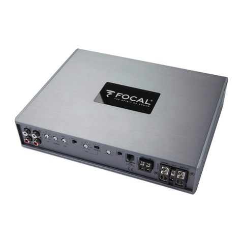
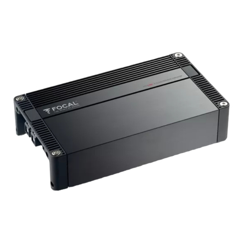
Focal FDP 1.900 Quick guide

'f
FOCAL
FDP
1.900:
ONE
CHANNEL AMPLIFIER
Operation I Configuration
POWER
PER
CHANNEL:
• 1
X
500
wRMS
ra
4ohms
• 1
X
850 wRMS
ra
2ohms
• 1
X
500 wRMS
ra
1
ohms
• 1 x 1700 wRMS (Two
FOP
1.900s Bridged
ra
4
ohms
only]
INPUT/OUTPUT
CONFIGURATIONS
Because
this
is a one channel
amplifier,
if
both
left
and
right
inputs
are used, they are mixed to mono, which is
useful
for
subwoofers.
CROSSOVER
CONFIGURATION
The
24
dB
per
octave crossover can
be
adjusted so this
amplifier
can function as:
1.
Full range
2.
Low Pass
for
a subwoofer.
3.
Band Pass
for
a
subwoofer
or
midbass of a 3 way speaker.v
4.
High Pass
for
a midbass, midrange
or
tweeter.
• The
amplifier
can
be
used
full
range
with
switch in
HP
position and frequency set to
10Hz.
HP is always on so
it
can be used as a subsonic filter.
HP
X1
frequency range is
10Hz
to 400Hz.
HP
X1
0 frequency range is
100Hz
to 4000Hz.
LP:
Adjustment
range is
30
Hz
to 350 Hz.
Band Pass with switch in LP position and adjusting both HP and LP to desired frequency.
• The remote volume
control
is always active.
There is a clip distortion
light
on
the remote volume control.
If you see
this
light
on, reduce volume
until
the light goes out
so
that
you
do not damage your speaker.
• Phase is continuously adjustable between 0 degrees and 180 degrees. Adjust
by
measuring frequency response
at the crossover frequency. Frequency response should
be
as smooth as possible.
•
40Hz
EQ
is adjustable between
OdB
and +6dB.
Measure the subwoofer frequency response and adjust
EQ
to get the smoothest frequency response.
Avoid excess
EQ
boost because
this
will
mak
e the subwoofer sound
"muddy"
a
nd
cause the am
plifier
have clip
distortion prematurely.
AUTOMATIC
POWER
TURN
ON/OFF
1.
Th
e best way to
automatically
turn
the
amplifier
power on and off is to use the
REM
wire
from
your
so
ur
ce
radio
connected to the
REM
a
mplifier
termin
al.
2.
If your
original
equipment stereo
or
source radio has a BTL
amplifier
then the
RCA
inputs have
an
auto
turn
on
sensing circuit. When you connect the high level BTL speaker
wires
to the
RCA
input the
REM
wire
is not
necessary.
1

RCA
INPUT,
BOTH
LOW
LEVEL
AND
HIGH
LEVEL.
The
amplifier
LEVEL
control has sufficient adjustment range for both low level and high level input into the
RCA
jacks. A factory source radio that does not have
RCA
output, using the
wires
that are connected to the speakers, can
be
directly connected to the
RCA
jacks when the
amplifier
LEVEL
control is adjusted to
8V.
SETTING
LEVEL
• Set the
amplifier
LEVEL
control to
minimum
before you
turn
on
the
amplifier
for the
first
time
.
• For lowest distortion and lowest noise the
amplifier
LEVEL
should
be
set at the lowest setting
that
yields
sufficient loudness
without
distortion. For lowest noise
your
source radio volume control should
be
near
maximum
that does not cause distortion.
•
To
find the best
amplifier
LEVEL
setting:
With the
amplifier
LEVEL
at
minimum,
slowly increase the source radio volume to around 3/4 without distortion.
Then, slowly
turn
up the
amplifier
LEVEL
control to the
maximum
desired loudness. Listen very carefully and
turn
down the
amplifier
LEVEL
control
if
you hear any distortion.
SETTING
SUBWOOFER
HIGH
PASS
SUBSONIC
FILTER:
• A subwoofer should have a high pass
filter
often called a subsonic filter. The purpose of a subsonic
filter
is to
limit
very low frequencies
that
your subwoofer
can
not play loud enough without damage. Removing subsonic
frequencies can
allow
your subwooferto play louder.
• For a sealed
box
the high pass is typically set between
10
Hz
and
30Hz
to increase power handling capacity.
• For a vented
box
the high pass
filter
must
be
set 5
Hz
lower
than the port tune frequency to prevent woofer
damage.
2

ONE
AMPLIFIER
IN HP, LP
OR
BP MODE:
®
G
OU
T
(±)
G 2
I
A2
I
®
G
OUT
(±)
G
0 2
150
85~40
60
·
0.
·
3008
40 350 0 180
LP PHASE
50Hz
150
85~240
60 ·
0.
·
3008
40 350 0 180
LP PHASE
HP
40Hz
HP
LP
·8·
D
0 +6dB
EQ
LP
40Hz
HP
LP
·8·
D
0 +6dB
EQ
50Hz
x1
x10 x1
50
22
115
D
15·~
·
200
V
RANGE
10 4oo
I
HP__j
MASTER
0 M
I A
~D~
C E
T R
DIU
SUB
CONTROL
(8
CE:
REMOTE
SUB
CONTROL
20Hz
x1
x10 x1
50
22
8
115
D
15
.
+ .
200
• • RANGE
10 4oo
I
HP__j
0 M
~D~
E T
C E
T R
DIU
SUB
CONTROL
(8
CE:
3
0::
w
~
0
a..
0::
w
~
0
a..
GNDO
REM
BATT®
FDP
1.900
GNDO
REM
BATT®
FDP
1.900

TWO
AMPLIFIERS
IN
BRIDGED
MODE:
TWO
FPD
900.1
amplifiers
are required.
Amplifier
#1
will
have "
MASTER
"switch selected.
Amplifier
#2
will
have "
DIRECT
"switch selected.
Crossover and level controls
will
only function
on
MASTER
amplifier
#1.
By selecting "
DIRECT
"
on
amplifier
#2
all
crossover and level controls are bypassed and the LEFT input channel
must
be
used.
Master
Amplifier
#1
will
receive the source signal
on
left and
right
channels.
Master
Amplifier
#1
RCA
"out_
..
will
connect to
direct
amplifier
#2
RCA
"LIN".
The LEFT input channel
must
be
used.
The !speaker
+I
will
connect to
Amplifier
#1
I+
speaker!.
The [speaker
-I
will
connect to
Amplifier
#2
I+
speaker!.
The [speaker
-I
on
Amplifier
#1
will
connect to [speaker
-I
on
Amplifier
#2.
A3
(2
AMPS
BRIDGED)
50Hz
LP
HP
LP
D
150
85
~
240
60
·
~
·
3000.
40Hz
·
0.
·
40 350 0 180 0
+6
dB
LP PHASE EQ
20Hz
x1
x10
x1
50
22
115 D
15 •Q • 200
V
RANGE
10
• ·
4oo
I
HP
___j
REMOTE
SUB
CONTROL
MASTER
D M
j
otDI
SUB
'---+
-
-+-
-'
0:::
w
3:
0
c..
CONTROL
CB
CB
CE
DIRECT
®
150 40Hz
HP
LP
x10 x1
D M
50
~D~
Dl
G
85840
·
0.
·
D 22 115 D
60 • . +
.··
3000.
G
E T
0:::
15 ·8 · 200
w
c E
3:
• • RANGE . .
T R
8v • • 0.
2v
0
OUT
c±)
IN 40 350 0 180 0 +6dB 10 4
:_____j
c..
GG
LP PHASE EQ HP
SUB
CONTROL
CB CB
0 2
CE
4
GNDO
REM
BATT®
FDP
1.900
SUBWOOFER
REM
BATT®
FDP
1.900

MULTIPLE AMPLIFIERS IN PARALLEL CASCADE MODE:
TWO
or
more
FPD
900.1
amplifiers
are required.
• Use
this
mode
when
you have several speakers
that
will
use the same crossover and loudness
setting
and
will
have one
amplifier
on
each speaker.
•
One
example is a
dual
voice coil
subwoofer
and you use one
amplifier
on
each voice coil.
• A second example is you have several
subwoofers
and
will
use one
amplifier
on
each
subwoofer
.
Amplifier
#1
will
have "
MASTER
'"
switch selected.
Amplifier
#2,3,4....
will
have "
DIRECT
"
switch
selected.
Crossover and level
controls
will
only function
on
amplifier
#1.
By selecting "
DIRECT"
'
on
amplifier
#2,3,4....
all
crossover and level
controls
are bypassed and the LEFT input
channel
must
be
used.
Master
Amplifier
#1
will
receive the source
signal
on
left
and
right
channel.
Master
Amplifier
#1
RCA
"out+
"'
will
connect to
direct
amplifier
#2,3,4
..
..
RCA
"
LIN
".
The LEFT
input
channel
must
be
used.
One
speaker+
&
-will
connect to one
Amplifier's
+ & -.
A4
(2
AMPS
PARALLEL)
REMOTE
SUB
CONTROL
50Hz
LP
20Hz
x1
MASTER
,----\-\---l------
±--+-±
1-----
~
1------------.
150 40Hz
85040
·
0.
·
60 •
.+.··
3000.
40 350 0 180 0
+6dB
LP
PHASE
EQ
0
40Hz
·
0.
·
0
+6dB
EQ
HP
LP
D
HP
LP
D
x10
x1
50
22
115 D
15 ·
8·200
• •
RANGE
10
4:____j
HP
x10
x1
50
22 115 D
15 ·
r0·200
V
RANGE
10.
·
4oo
I
HP
___j
5
Q
"
\_J,
"
8v
• • 0.
2v
D M
~D~
E T
C E
T R
DIRECT
D M
~D~
E T
C E
T R
Dl
SUB
CONTROL
CE:
SUB
'---
1
--
1-
--'
CONTROL
(8
CE:
0::
w
;:
0
0..
0::
w
~
0..
GNDO
REM BATT@
FDP
1.900
GNDO
DUAL
VOICE
COIL
SUBWOOFER
REM BATT@
FDP
1.900

POWER
FUSES
&BALANCED/UNBALANCED SWITCH:
1.
900
POWER
FUSES
~TO
USE:
Remove
the
end
panel
by
the
power
terminals
2 x
25
amp
ATC
fuse
1.900
BALANCED/UNBALANCED
SWITCH
~TO
USE:
Remove
the
end
panel
by
the
RCA
jacks.
The standard
switch
position is
input
ground "ON".
Flip
the
switch
"OFF" changes the
input
to
"balanced
input
floating
ground".
To
flip
the switch, use a
small
pick
or
jewelers
screw
driver.
6

TROUBLESHOOTING:
?
FOCAL
SIGN
DOES
NOT
LIGHT
1.
Measure the voltage at the
amplifier
power
terminal.
It should
be
between
12
and
15
volts.
2.
Measure the voltage at the
amplifier
REM
terminal.
It should
be
between
12
and
15
volts.
3. If you are using BTL high level for automatic
turn
on,
try
connecting a
REM
wire.
4.
Check your power and ground connections to
be
correct
polarity+
and-
and they are tight.
5.
Check battery connections.
6.
Check the fuse
in
the
REM
wire.
7. Check fuse at battery.
8.
Check fuse inside amplifier.
The fuse is inside the
right
end
cap
beside the power
terminals
.
The recommended
ATC
fuse size is two
25
amp.
?
FOCAL
SIGN
IS
FLASHING
1.
Is
the amp very hot?
Wait a few minutes
for
it
to cool down.
You
need to get more fresh cool
air
to the
ampl
ifier.
Do
not cover the
amplifier
or
mount
it
flush into a hole.
2.
If the amp is cold and the Focal sign is flashing, there is an internal fault. The
amplifier
must
then
be
returned
for service.
?
NO
SOUND
1.
Is
the Focal sign
light
off
or
flashing?
2.
Is
the source radio
on
and is there a sound signal coming from the source radio?
3.
Use
an
ohm
meter
and measure the speaker wires for
short
circuit.
4.
Check connections for
small
"wire whisker" that may
be
shorting between
amplifier
terminals
or
speaker
terminals.
5.
Use
an
ohm
meter
and measure the speaker for
short
circuit.
6. Double check your connections
to
the source radio.
7.
Are you using the correct source radio wires and are they plugged into the correct
amplifier
RCA?
8.
Double check your connections
to
the speakers and speaker crossovers.
9.
Check that
all
amplifier
switches are in the correct positions for your speaker set up.
?
AMPLIFIER
BLOWS
FUSE
WHEN
YOU
TURN
IT
ON.
1. Power and ground may
be
reversed.
Check+
and-
polarity at
amplifier
and at battery.
?
SUBWOOFER
REMOTE
VOLUME
CONTROL
DOES
NOT
FUNCTION.
1.
Check that Remote Volume Control wire is plugged into the
amplifier
securely.
2. The Remote Volume Control
will
not function
if
the amp switch is "DIRECT". The switch must
be
in "MASTER".
7

~
SUBWOOFER
REMOTE
VOLUME
CONTROL
LED
LIGHT.
1.
While playing music the LED
light
should
be
Green.
Occasional red
LED
light
flash indicates
that
the
amplifier
has reached
maximum
loudness.
2.
If the red LED
light
flashes
with
the beat of the music,
TURN
DOWN
THE
VOLUME before you damage
your
speaker.
3.
If the red LED
light
is on continuous,
TURN
DOWN
THE
VOLUME before you damage your speaker.
WARRANTY
INFORMATION:
Focal America I Orca Design & Manufacturing supports
their
products and guarantees
them
to
be
free of
manufacturing defects
for
a period
of
1 year (non-transferrable) from the date
of
purchase, if purchased
from
and
authorized retailer. This
time
period is extended to 3 years (non-transferrable) from the date
of
purchase, if the amplifier is purchased from and installed
by
an authorized retailer, and
no
alterations are
made to the installation
or
setup of the
amplifier
outside of the authorized retailer.
This manufacturing warranty does not extend to situations involving physical or installation damage, misuse,
abuse, or modification. If an
amplifier
malfunctions, please
return
it to the authorized
retailer
from which the
amplifier
was purchased to have the
amplifier
and/or
installation inspected and to have the
warranty
period
verified from date of purchase.
The authorized dealer
will
then
work
with Focal America I Orca Design & Manufacturing to obtain service,
if
necessary. If found to
be
a defect due to manufacturing, the
item
will
be repaired
or
replaced
with
a refurbished
amplifier. The
amplifier
will
be
returned to the authorized
retailer
when repairs are complete,
so
that
the
dealer
can
return
the
amplifier
to you,
or
reinstall
the
amplifier
to maintain the above mentioned
warranty
timeline.
TECHNICAL
SPECIFICATIONS:
One
X
500
watts
at less than
1%
THO
into 4 ohms
One
X
850
watts
at less than
1%
TH
D into 2 ohms
Two amps can
be
bridged, one X 1700
watts
at less than 1%
THO
into 4 ohms
Frequency Response 5
Hz
to
25
kHz.
S/N ratio
90
dB
RCA
input
ca
n use a BTL
so
urce
or
common ground source.
RCA
switch select balanced floating ground
or
grounded to
minimize noise.
Input sensitivity 200mV to
10
volts
Slew Rate
13
VI uS
Variable high pass cross
ov
er
10Hz
to
4000H
z,
24
dB
Linkwitz
-Riley
Variable
low
pass crossover 40
Hz
to 350
Hz,
24 dB Linkwitz-Riley
Variable band pass crossover
10Hz
to 350Hz, 24 dB Linkwitz-Riley
Variable bass
boo
st, 0 to +6dB
at
40
Hz
.
Continuous phase adjust
ment
from 0 to
180
degree.
Subwoofer remote volume
co
ntrol
includes a clipping indicator light.
Recommended
DC
voltage operating range 11.5 to 14.4
volt
s.
Minimum
DC
vo
ltage operating range 8 to
16
volts.
Length
7.71
inches Width
10
inches Height 1.97 inches
Weight 6 pounds
8 65-C1
299
-MA
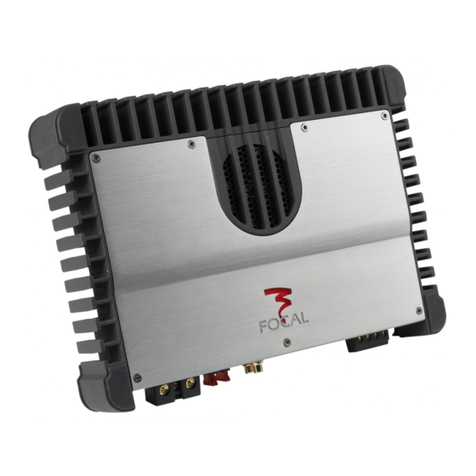
Table of contents
Other Focal Amplifier manuals

Focal
Focal FPS 2160 User manual

Focal
Focal Solid User manual

Focal
Focal PS 165F/PS 130F User manual

Focal
Focal SOLID 1 User manual

Focal
Focal SOLID 4 User manual

Focal
Focal 100 IWSUB8 User manual

Focal
Focal 100 Series User manual

Focal
Focal Premium FPX Series User manual

Focal
Focal POWER AMPLIFIERS User manual

Focal
Focal AP-4.340 User manual

Focal
Focal FPX User manual

Focal
Focal FDP 6.900 Quick guide

Focal
Focal FPD 900.6 User manual

Focal
Focal FDP 1.2000 User manual

Focal
Focal FIT 9.660 User manual

Focal
Focal FDP 6.900 Quick guide

Focal
Focal FDP 4.600 Quick guide

Focal
Focal FDP 6.900 V2 User manual

Focal
Focal 100 Series User manual

Focal
Focal FPD 900.1 User manual