SOLID
AMPLIFIER
User
manual
a
1)
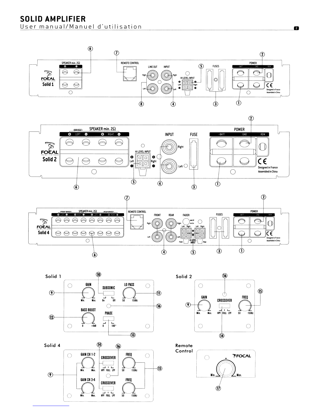
Amplifier
fixing
The SOLID 2
amplifiers
can be fixed with the 4supplied screws
and
the SOLID 1
and
4with the 5screws. It
is
recommended
to
insert a
MDF
sheet between the fixing surface
of
the vehicle
and
the
amplifier
(fig.
B).
2)
Installation:
&.
Unplug
the
negative
power
supply
terminal
of
the
battery
before
starting
the
installation
(fig.
A).
2.1} Remove the protection cap
of
the
amplifier
with the
help
of
the supplied Allen key (fig. C).
2.2)
Connect
the positive
power
supply
terminal
of
the
amplifier
to the battery
Please refer to the
table
below
to
know
the suitable
power
supply wire
gauge.
Connect
the positive
power
supply
wire
to
the
amplifier
("
+BATI"), then convey this wire towards the battery. Install afuse-box integrating afuse with the same value as the
one
in the
amplifier
at
40cm
maximum
of
the battery positive
terminal
(figD).
Connect the fuse-box
to
the battery positive
terminal.
The SOLID
amplifiers
are
supplied with the
Auto
Power function. This function replaces the
traditional
"remote"
terminal
and
provides
an
automatic
switch-on
of
the
amplifier
as soon as it gets ahigh-level signal (starting the head unit).
Positive power
0-lm
1-2m 2-3m 3-4m 4-5m 5-6m
supply wire length
SOLID
16mm2/
8mm
2/16mm2/20mm2/25mm2/
35mm'
/
9AWG* 8AWG 5AWG 4AWG 3AWG 2AWG
SOLID
22,5mm2/
6mm'
/
8mm
2/lOmm2/16mm2/16mm2/
13AWG
9AWG
8AWG
7AWG
5AWG
5AWG
SOLID
46mm2/lOmm2/16mm2/20mm2/
25mm'
/35mm2/
9AWG 7AWG 5AWG 4AWG 3AWG 2AWG
*AWG :American Wire Gauge
2.3)
Connect
the
amplifier
ground
to
the vehicle chassis
Use a
power
supply wire with the same
gauge
as the
one
linking the positive
power
supply
terminal
of
the
amplifier
and
the
one
of
the
battery. Always connect the
ground
on
a
metallic
part
perfectly scrubbed
of
any
paint
or
varnish trace. Then connect the
other
extremity
of
the
ground
wire to the "Power
GND"
ground
terminal
of
the amplifier.
2.4)
Connect
the source to the
amplifier
Connect,
up
to
your
choice, the low-level (INPUT)
or
high-level (HI-LEVEL INPUT) wires.
Low-level
wiring
(INPUT): This connection
mode
offers a
higher
quality
compared
to
the high-level wiring.
You
should then
favor
the
low-
level
wiring
if
you have this possibility.
Connect
the RCA wire to the
"INPUT
Left"
and
"INPUT Right"
terminals
of
the amplifier.
Convey
the
wire to the source
and
connect it to it on the RCA terminals respecting polarities (fig.
E).
High-level
wiring
(HI
LEVEL
INPUT}: This connection
mode
permits
to
convey the signal between the head
unit
and
the
amplifier
in the case
that
the
head
unit has
no
low-level outputs (RCA). Use the supplied high-level connector
and
weld each
wire
to
the
corresponding
speaker
wire respecting polarities (fig. G). Link the
head
unit speaker outputs
to
the connector wires
and
plug
in the
connector
to
the amplifier.
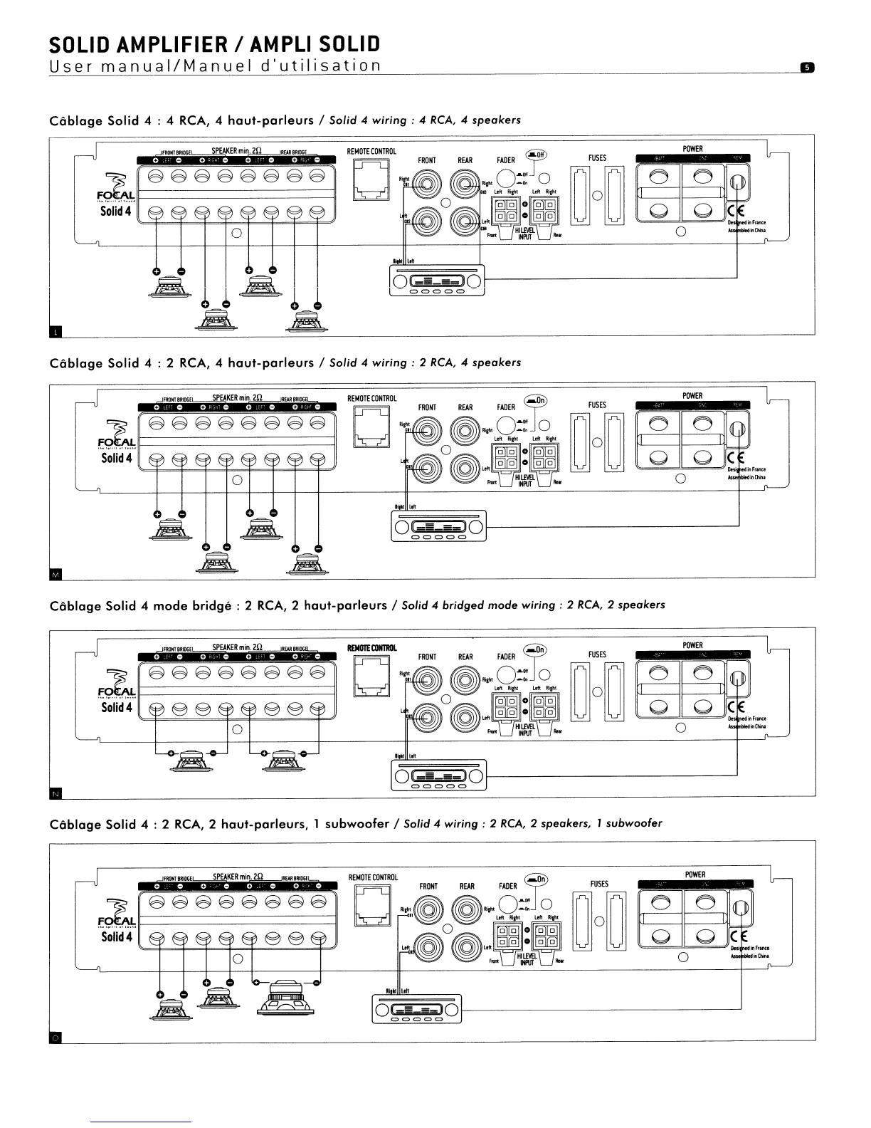
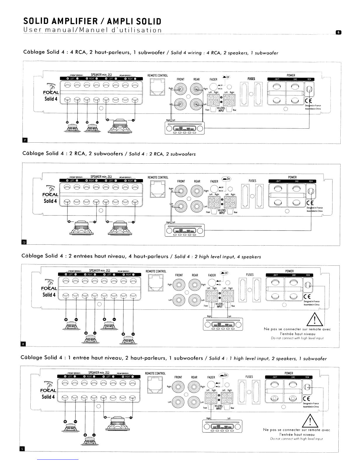
NOTE:
The SOLID 4
amplifier
is
supplied with
two
high-level connectors in
order
to
link
together
the
whole
head
unit
speaker outputs with
the
amplifier
inputs
(see
fig. H
for
the
wiring
polarities).
NOTE:
The SOLID 1
amplifier
is
provided with alow-level
output
(LINE OUTPUT). This
output
permits
to
convey the low-level signal
towards
another
amplifier. This
output
is
not
filtered
and
thus retranscribes the transmitted low-level signal by the
head
unit
without
any
change.
2.5}
Connect
the REMOTE
CONTROL
(only supplied with Solid 1
and
Solid 4amplifiers).
Connect
the remote control
wire
with the REMOTE
CONTROL
input
of
the amplifier, then connect it
to
the remote control. This control must be placed next to the driver, easy
to
access
and
it
permits the
gain
control
of
the
amplifier
(channels 3
and
4
of
the SOLID 4
amplifier
and
channell
of
the SOLID 1
amplifier).
2.6}
Connect
the speakers to the
amplifier
The SOLID 2
and
SOLID 4
amplifiers
are
compatible
with
an
impedance
load
between 2
and
4
Ohms.
The SOLID 1
amplifier
can
take
an
impedance
load
between 1
and
4
Ohms.
If\.
Use a
wire
with 1
.5mm2
minimum
gauge.
Connect
the speaker(s) to the
SPEAKER
terminals
of
the
amplifier
respecting polarities
~
(fig. I
to
R).