manuals.online logo
Brands
  1. Home
  2. •
  3. Brands
  4. •
  5. Focke-Wulf
  6. •
  7. Toy
  8. •
  9. Focke-Wulf FW-44 Stieglitz 1932 User manual

Focke-Wulf FW-44 Stieglitz 1932 User manual

FockeWulfFockeWulf
FW-44 StieglitzFW-44 Stieglitz
19321932
Assembly and finishing Manual
for ARF stand-off scale model
in 1:5 scale.
Historical data and presentation.
Model design and construction drawing by
Göran Kalderén ©
Rev.2000-05-25
Focke Wulf FW 44 ARF 2
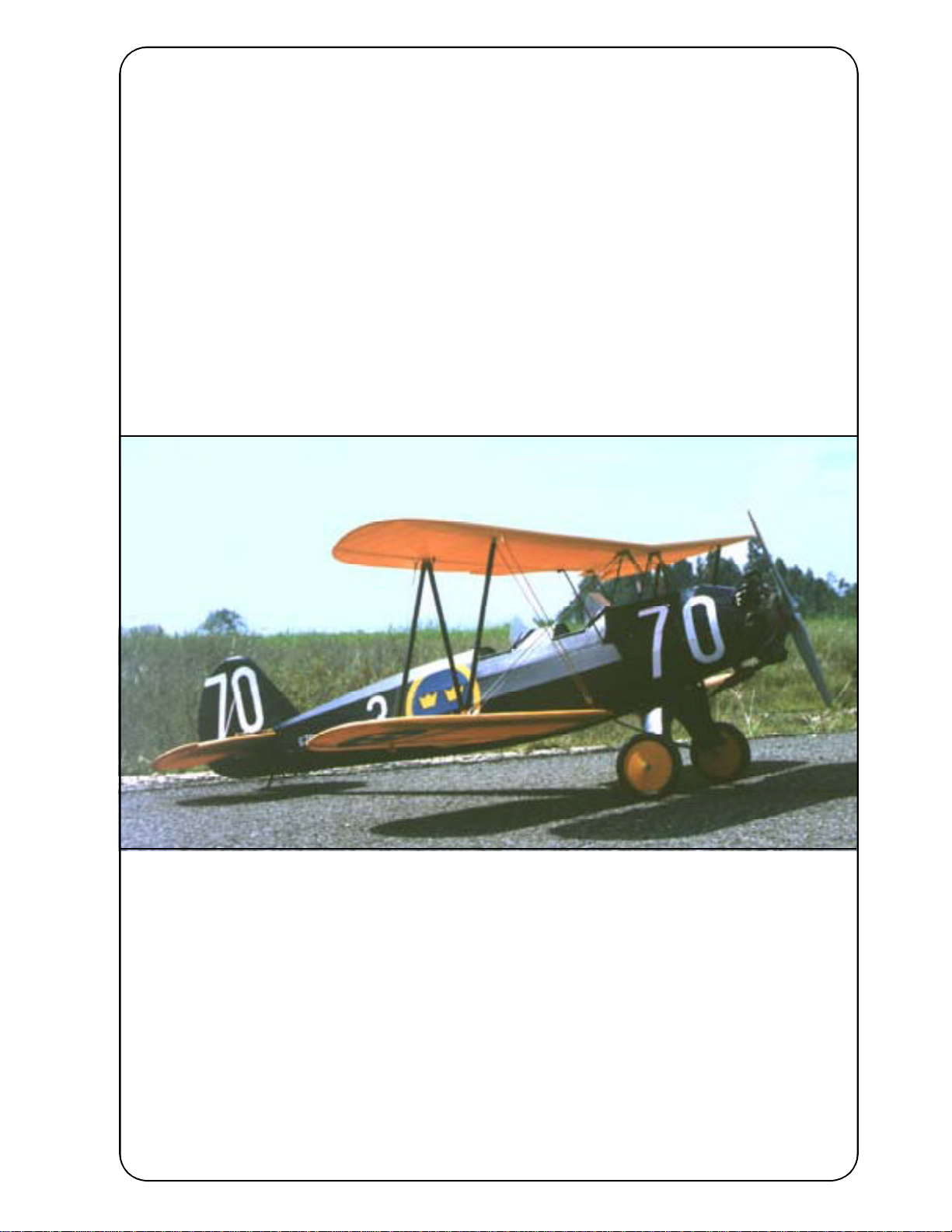
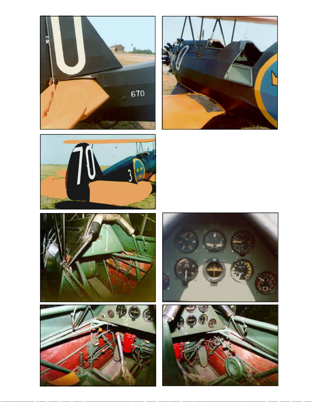
Swedish Airforce aircraft No 670, type FW44J, was built by Focke Wuld Flugzeugbau GmbH
inGermany.Thesepicturesweretaken in August 1976at Malmen by Linköping,Sweden, show all
relevant details. This year the Swedish Airforce celebrated its 50th year anniversary. The aircraft
was transferred from Wing No 3 to wing No 5 shortly thereafter.
Focke Wulf FW 44 ARF 3
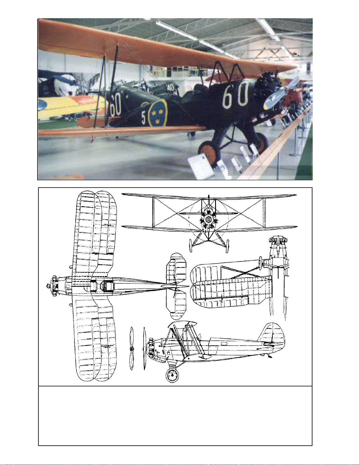
Focke Wulf FW44J, here at the F3 wing
airfield, Malmslätt near Linköping, Sweden,
preserved by the Swedish Airforce Museum.
This aircraft is still in good flying condition and
hasbeenflownatairshowsduringrecentyears.
This aircraft is one of several survivors in
Sweden.Thecockpitphotosrevealthatonlythe
rear cockpit has full instrumentation. This was
not common but may be a result of the aircraft
servingas glidertow airplane, untilhanded over
to the museum.
Focke Wulf FW 44 ARF 4
Specifications:
Type: Focke Wulf Fw 44J:
Function: Sports trainer
Crew: 2
Engine: One Siemens Bramo Sh 14a
Wingspan: 9.01m
Length: 7.29m
Height: 2.83m
Wing area: 20sqm
Weight: Empty: 525kg
Loaded weight: 770kg for aerobatics
870kg for training
900kg for touring
Maximum speed: 115 mph
Cruising: 107 mph
Service ceiling: 12792 ft
Maximum range: 420 miles
Focke Wulf FW 44 ARF 5
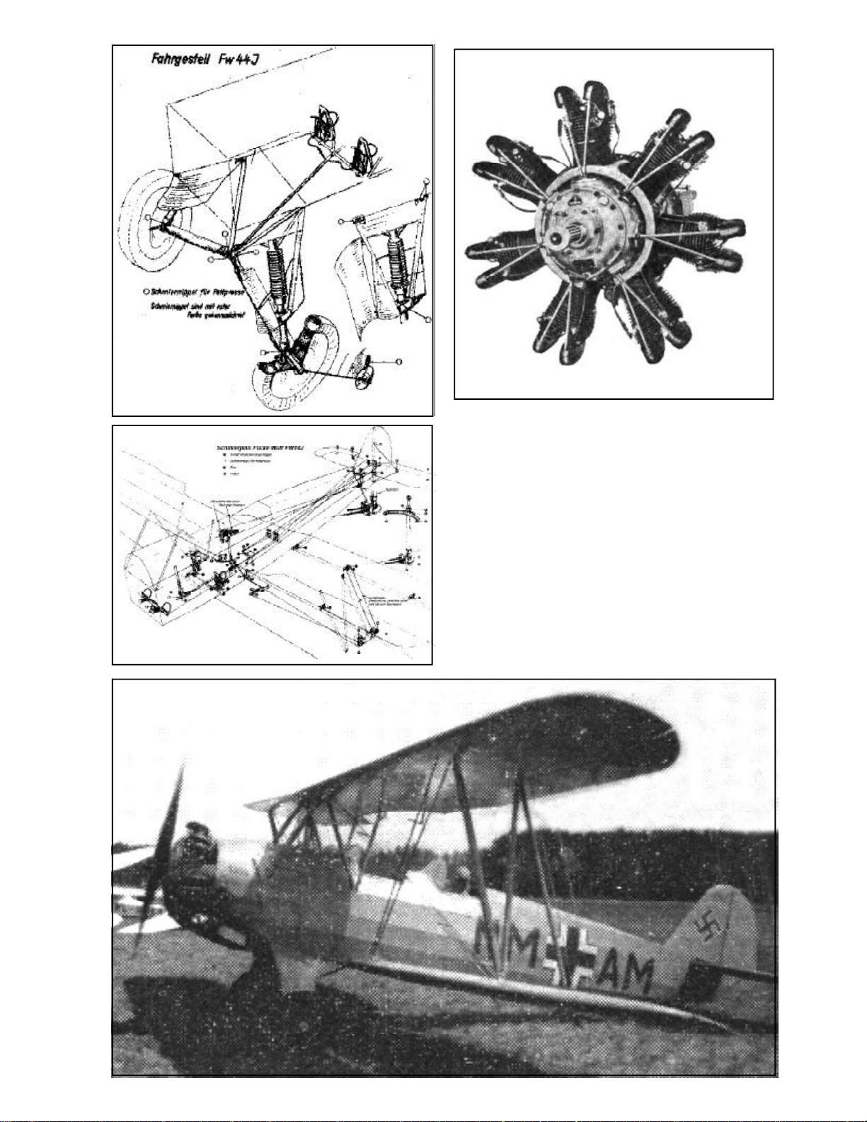
Righttop:Siemens Bramo Sh-14, 7cylinder ra-
dialaircooledengine,150 hp.
Lefttop:Originallubricationchartforlandinggear.
This chart gives a clear view of the landingear
design.
Leftcenter: Original lubricationchart forairframe
controls.
Below:FW44c as trainerin the GermanAirforce
in 1939 -1945 with grey camouflage paint and
contemporary unit markings.
Focke Wulf FW 44 ARF 6
Focke Wulf FW-44 Stieglitz
When Kurt Tank joined the Focke Wulf
FlugzeugbauGmbH astechnichal chief,his first
design to take to the air in 1932 was the Fokke
WulfFW-44Stieglitz(Goldfinch).Itwasdesigned
to meet the requirements of a number of
German expert aerobatic pilots like Gerd
Achgelis, Emil Kropf and Ernst Udet. It proved
to be an excellent aircraft fully capable of the
aerobaticmaneuvresperformedby thesepilots.
Thefirst prototype wasequipped withan 150 hp
Bramo Siemens Sh-14a radial engine.
A large number of Stieglitz were sold and
deliveredtocountrieslikeBolivia,Bulgaria,Chile,
China, Finland, Hungary, Sweden, Rumania,
Turkey and Slovakia.
Demandcouldnotbemetwithin thefactory
and several aircraft were built under licence in
Sweden,Argentinia, TurkeyandBrazil.
Work began on the Fw 44 in 1931 shortly after
the amalgamisation of Focke-Wulf wit Albatros-
Flugzeugwerke and was the first complete air-
craftdesignedatFocke-Wulfundertheguidance
of Kurt Tank. It was designed as a two-seat bi-
planefor sportingand primary traininguse. The
Fw 44 was instrumental in establishing Focke-
WulfFlugzeugbauwhensubstantial orderswere
receivedfor theplane.
Theplane firstflew inlate summer1932 pow-
ered by a seven cylinder air-cooled radial en-
gine,the BramoSiemens Sh 14a,but displayed
many faults. Considerable test flying by Kurt
Tank lead to much redesign, The Fw 44
emergedas an aircraftwith excellent flightchar-
acteristics and strength.
TheFw 44’s reputation wasmuch enhanced
byits use as anaerobatic display aircraft bythe
top german pilots of the day.
The Fw 44C, the main production model,
was a strut and wire braced biplane, the wings
having equal span and slight sweepback, stag-
geranddihedral.Thelowerwings wereattached
tothebottomofthefuselage,theupperbystruts.
The wings were of wood and fabric. The fuse-
lage was of welded steel construction covered
by metal panels as far back as the cockpit and
theremainder by fabric.
Ourmodel is based onone of the remainingair-
craft,the FockeWulf FW44 J,now ondisplay in
theSwedishAirforceMuseum inLinköping,Swe-
den.
Proud student pilot in front of his aircraft
Restored FW 44 j flying in California, USA.
Markings from 1937 - 1940 period of the
SwedishAirforce.
Present restored FW 44 c in Germany (note the
tailwheel, necessary for hardsurface runways)
and below our model of the A/C to the right.
Focke Wulf FW 44 ARF 7
German Airforce paint scheme in
the early part of WW2
The Model
We have chosen the scale of 1:5 rende-
ring a model size that i easy to fly but also
relatively easy to transport. Both the upper and
the lower wing panels can be removed for
transportation which gives very limited
requirement for transportation size. We
recommend a .90 4-stroke or a .75 2-stroke
engine.The4strokeenginefitsinuprightposition
and blends very nicely with the dummy engine
cylindres. This aircraft was designed for
aerobaticsof thetime andcan beflown through
advancedmanouevres. At thesame time itwas
a trainer and the low speed behaviour is rather
docileandallows for the pilotto think...
This model has all control surfaces
connected in scale fashion. The ailerons are
actuatedviaconnecting rodstobellcranksinthe
lower wings, which i turn are connected with
wires via pulleys to the ailerons in the lower
wings. The upper ailerons are connected with
dual wires from the lower ailerons in scale
fashion. The elevator is actuated via pull-pull
cables from the control column. The rudder in
turn has conventional pull-pull cables to the
rudder bar.
The finished model is painted in 1940
SwedishAirforce liveryand furtherdetailing can
bemade asper documentation. Thismodel can
also be supplied in various German liveries.
Model specification
Wingspan: 72" (180 cm),
Length: 58.4" (146 cm),
Wing area: 1138 sq inch (80 dm²)
Weight: 11 lbs 5 oz. (5400 g)
Wing Load: 23.5 oz/sq' (70 g/dm²)
Engine: .60-.75 cc (10-12.5cc) 2-
stroke, .80 - .90 4 stroke
Covering and finish
Themodel is coveredand painted fromthe
factory. If you are going to use a glowplug or
gasoline engine for flying, you must coat the
interior of the engine compartment with a fuel
proof paint.
Installation of engine and radio
We recommend that you don't overpower
thismodel. It willfly happily witha .60 -.75 stan-
dard 2-stroke engine. No side or down thrust is
deemed necessary but can easily be
incorporated at this time. Details on page 8-9.
Assembly of the Focke Wulf FW44
All parts have been assembled at the
factoryandonlydisassembledfortransportation.
Rudder and elevator and aileron wires are
factoryadjusted but may needsome tensioning
adjustment after a while. Aileron bellcranks are
adjustable to the connecting rod.
Assembly of the tail unit
1.Attachhorizontal tailto fuselageusing
4 pcs 4 mm nylon countersunk screws. Make
sure that stabilizeris flat against fuselage.
2. Insert fin with vertical spar into
fuselage. Attach fin using 2 pcs 4 mm nylon
countersunk screws. Make sure that fin is
perpendicularto stabilizer.
3. Attach the fin supports with a 2mm
screwandnutinthefinand#2x1/4"sheetmetal
screws in the stabilizer.
4. Attach the stabilizer support struts to
the fuselage using # 2 x 1/4" screws.
5. Attach the rudder with the hinge pins
andconnect therudder wiresto therudder horn
andtheelevator wires to theelevator horns.
Checkthe action ofelevator andrudder.
Continued on page 10 >
Focke Wulf FW 44 ARF 8
Installation of engine, tank and radio
We installed an OS .90 4-stroke
surpass engine and used a flexible header
to lead the exhaust under the fuselage in a
near scale fashion. We also used a 12 Oz.
tank. 1. Remove the dummy engine by
loosening the two screws in the front col-
lector ring and remove the 2 2 mm screws
andnuts that holds theexhaust tube.
2.Drilltheholesinthe enginemount
and install 4 6-32 blind nuts for the engine
bolts. 3. Cut out for the engine in the top
coverpanel.and drillthehole fortheheader
intheenginemountingboardandinthebot-
tom cover.
Header exit in
line with dummy silencer
Onedummy cylinder is
removed
Throttle
linkage
and fuel
tubings
Header
Cut out in
top panel
Dummy
exhaust tube may be left
for appearance
Radio switch on
forward cockpit
instrument panel
Landinggear secured
with 3 mm bolts and
lock nuts
Fuel
filing
tube
Throttle needle
Focke Wulf FW 44 ARF 9
4. Remove one cylinder
from the top of the dummy engine
andadjust thecutout inthe “crank-
case”. Replace the dummy engine
andcheckforfit.TheOS .90blends
nicelywith the dummy. Cutout and
adjust the rear portion of the ex-
haust tube and bend the header
tube to suit the outline. Attach the
header tube with a clamp to the
dummy silencer.
5. Install the throttle servo
in the top compartment and con-
nect to the throttle lever.
6. Install the tank with sili-
cone tube connections.
7.Install the aileron,rudder
and elevator servos in the respec-
tive servo trays. Not that the two
aileronservos are interconnected.
8. Place the receiver and
thebatterypackalongthetank.The
switchcanbe mountedon thefrom
cockpit instrument panel.
9. Connect the aileron ser-
voswith ball linksor clevices tothe
aileron push rods.
10.Thesameapplies tothe
rudderandelevatorservosconnec-
tion to the rudder bar and the con-
trol column.
Check for correct throws on the
control surfaces. The elevator and
aileronsshoulddeflect20°,therud-
der almost 30°.
Rudder and elevator servo
in forward tray Twin coupled aileron servos in
rearward tray
Tank in the upper tray
center,throttle servo
to the right
Receiver and
battery pack
to the left, se-
cured with
rubber
bands
Header is
routed to
bottom
aluminum
panel and exits
in line with
dummy
exhaust
Focke Wulf FW 44 ARF 10
Dummy engine is
built from wood and
metal. Aileron control
is by wire per
prototype. Rudder /
elevator control by
wire to control
column and rudder
bar.Spung tailskidin
scale fashion.
The wood and metal construction of the model
Builtup
dummy
engine
Functional
scaleaileron
control
system
Focke Wulf FW 44 ARF 11
Landing gear has scale oleo, rubber
dampened, spring action as the full size
aircraft. Right hand side aluminum
panel removed.
The elevator is actuated with the joy-stick and
the rudder with the rudder bar.
Assembly of wing panels
1.Pushthelowerwinghalvesintotheholes
in the fuselage.
2. Attach the upper wing using the 4 Allen
6-32screws supplied(note that thefront screws
arelongerand therearscrewsshorter).Connect
theaileronbellcrankswith pushrodstothe servo
inthefuselage.Installthelinkwiresbetweenthe
lower and upper ailerons. Adjust length so that
allaileronsare neutral. Check themovement of
theailerons. We recommendthat you attachthe
aileron pushrods in a manner, acheiving
differentialthrowof theaileron. Attachthe flying
wiresinplace.Attachthelandingwiresinplace.
3. Install the interplane struts. Secure with
2 mm screws and 2 mm lock nuts. Note that the
rear strut is adjustable at the attachment point
in the lower wing. By turning the screw up or
down you can adjust the wing outer section
incidence and the wash out of the upper wing.
Landing gear
Installthelanding gearbysecuringthelegs
with 3 mm screws and lock nuts. The centre
point schould be attached to the landing gear
support tripod with a 3 mm screw and lock nut.
Install the wheels on the shaft and secure
withthestoppers.Thistypeoflandinggearrelies
on the spring action of the rubber in the oleo
mounting in the landing gear. This is a very
efficient shock absorber. If worn out the rubber
can easily be replaced with a fresh, longer one.
Balancing
The center of gravity / balancing point
should be approx. approx. 13 cm (5.2")
measured from the leading edge center of the
upper wing. Placing the C/G up to ½" further
forward makes the airplane steadier but limits
the aerobatic capability. Make adjustments if
necessary to suit your flying taste..
FlyingThe prototype was flown with a OS .90
4-strokeFSwhichprovides amplethrust.Letthe
engine swing a 16x6 propeller if possible. This
givesbetter thrustoutside the bigdummy engine
and reduces sound to a more realistic level.
Flying characteristics are very forgiving
and willfly hapilyon halftrottle. Settheelevator
at zero angle for the first flight but be prepared
togive down elevator ifthe model climbs outtoo
steep. During the initial take off run you have to
compensate for the torque with right rudder but
as the speed builds up the rudder is returned to
neutrual.Thismodelshould flyoftheground and
notbepulled.
The landing approach can be rather
steep as per prototype but the flare out needs
almost full up elevator. Get the tail down to
maintain directional stability. Remember this
wasthe mountofmany ofthe Germanaerobatic
aces.
Happy landings!
Focke Wulf FW 44 ARF 12
P.O.Box 1229, Cebu City Centrl. Postoffice
Cebu City 6000, Philippines
Visiting address:
3343 Gun-Ob, Kinalumsan,
Lapu-Lapu City 6015, PHILIPPINES
Phone +63 32-340 7147, Cellular +63 917-3200 985
Telefax +63 32-340 7131, E-mail: [email protected]
Website http://www.gsilink.com/user/kwmairpl
KK
&&
WW
ModelModel
Airplanes Inc.Airplanes Inc.
What is in the box:
TheARFkit containstheparts showninthe picture.
Alltheparts arecoveredand painted.Allthe rigging wires are supplied in the correct lengths and need
onlytobeclippedtotheirpositions.
1. Fuselage with wing cabane
2. Landing gear with scale function
3. Scale wheels
4. Dummy engine with manifold
5. Scale propeller
6. Tail skid assy.
7. Fin with rudder
8. Stabilizer/elevator
9. Upper wing panels
10. Lowerwingpanels
11. Interplane struts
12. Aileron connecting wires
13. Landingwireswith turnbuckles
14. Flying wires with turnbuckles
15. Cabane cross-support wires
16. Assembly manual with scale documentation
16
1
2
3
4
5
6
8
11
10
9
4
8
7
12 13
14 15

This manual suits for next models

1

Popular Toy manuals by other brands

Elite Models Dream-S F3A 50E manual

Elite Models

Elite Models Dream-S F3A 50E manual

V-tech Zoo Jamz Xylophone Parents' guide

V-tech

V-tech Zoo Jamz Xylophone Parents' guide

V-tech Toot-Toot Friends Advent Calendar Parents' guide

V-tech

V-tech Toot-Toot Friends Advent Calendar Parents' guide

WOOD HEROES Trebuchet 1004 quick start guide

WOOD HEROES

WOOD HEROES Trebuchet 1004 quick start guide

Bluesky La Senorita Assembly instructions

Bluesky

Bluesky La Senorita Assembly instructions

V-tech Switch & Go Dinos Spark the Velociraptor Parents' guide

V-tech

V-tech Switch & Go Dinos Spark the Velociraptor Parents' guide

V-tech Spinning Lights Learning Hippo user manual

V-tech

V-tech Spinning Lights Learning Hippo user manual

V-tech Go Go Smart Wheels Car user manual

V-tech

V-tech Go Go Smart Wheels Car user manual

V-tech Talking Whiz Kid Frontier user manual

V-tech

V-tech Talking Whiz Kid Frontier user manual

LaserPegs EXPERIENCE Series Model instructions

LaserPegs

LaserPegs EXPERIENCE Series Model instructions

V-tech Click Box - Xtreme Power user manual

V-tech

V-tech Click Box - Xtreme Power user manual

V-tech Sort & Wiggle Tractor Parents' guide

V-tech

V-tech Sort & Wiggle Tractor Parents' guide

InVento Airglider 60 owner's manual

InVento

InVento Airglider 60 owner's manual

V-tech Splashtime Submarine Parents' guide

V-tech

V-tech Splashtime Submarine Parents' guide

OMPHOBBY M1 manual

OMPHOBBY

OMPHOBBY M1 manual

Stevens Aero Model Stella manual

Stevens Aero Model

Stevens Aero Model Stella manual

V-tech DOUBLE VISION NOTEBOOK user manual

V-tech

V-tech DOUBLE VISION NOTEBOOK user manual

Hobby King WARGO YAK55 instruction manual

Hobby King

Hobby King WARGO YAK55 instruction manual

manuals.online logo
manuals.online logoBrands
  • About & Mission
  • Contact us
  • Privacy Policy
  • Terms and Conditions

Copyright 2025 Manuals.Online. All Rights Reserved.