Focus Industries Handler I User manual

1Handler I, II & III Operator’s Manual - October 2008
Table of Contents
Warranty 3
Warranty Registration/Inspection Form 4
Sign Off Form 5
Introduction 6
Safety 7
Safety Decal Information 8
Assembly & Installation 9
Handler I Installation 9
Handler II Installation 14
Handler III Installation 20
Operation 28
Troubleshooting 36
Handler I Manifold Venturi Package Breakdown 38
Handler I Threaded Venturi Package Breakdown 39
2” Handler II & III Manifold Venturi Package Breakdown 40
3” Handler III Manifold Venturi Package Breakdown 41
Handler I, II & III Tank Parts Breakdown 42
System Specifications 43
Plumbing Package Assembly 44
Plumbing Package Operation 46


3Handler I, II & III Operator’s Manual - October 2008
Warranty
Focus Industries Inc. products are warranted for one year from date of purchase against
defects in material and workmanship and to perform according to specifications when
such products are properly assembled, installed, used and maintained. Warranty is
granted to original owner only.
Our obligation under this warranty is limited to repairing or replacing, at our option,
and excluding pumps, within 12 months of the retail delivery date. This obligation shall
not include any transportation charges or costs, or any liabilities for direct, indirect or
consequential damage or delay.
Warranty Limited or Void
Any use for purposes other than those for which the product was designed, operation be-
yond rated capacity, substitution of parts not approved by focus industries Inc., or altera-
tion or repair by others in such manner as in our judgment affects the product materially
and adversely shall void this warranty.
Warranty does not apply to any machine or part which has been repaired or altered in
any way so as in the company’s judgment affects its reliability, or which has been sub-
ject to misuse, negligence or accident.
Furthermore, component parts, equipment, accessories and items not fabricated by
Focus Industries Inc. are warranted only to the extent of the original manufacturer’s
warranty.
The gas and diesil engines, electric and hydraulic motors that are included with our pumps
are warrantied by the engine manufacturer, not by Focus Industries Inc. Please refer all
engine warranties to the authorized engine dealer near you.
Focus Industries Inc. reserves the right to make improvement changes on any of our
products without notice.
Warranty Claims Procedure
A warranty claim form must be completed at your handler dealer.
Defective parts for which a warranty claim is made must be returned to the dealer
within 15 days from the claim date.
1.
2.

4 Handler I, II & III Operator’s Manual - October 2008
Warranty Registration/Inspection Form
Warranty Registration
This form must be filled out by the dealer and signed by both the dealer and the customer at the time of delivery.
Customers Name Dealer Name
Address Address
City, State, Code City, State, Code
Phone Number Phone Number
Delivery Date Check One: Commercial Use Farm Use
Serial Number of Unit
Dealer Inspection Report Safety
Frame Fasteners Tight All Decals Installed
Chemical Hoses Tight Review Operating & Safety Instructions
Oil in Engine
I
the operator’s Manuel content, equipment care, adjustments, safe operation and applicable warranty policy.
Date Dealer’s Rep. Signature
Th
safe operation and applicable warranty policy.
Date Owner’s Signature

5Handler I, II & III Operator’s Manual - October 2008
Focus Industries Inc. follows the safety standard specified by the
American Society for Agricultural Engineers (ASAE) and the
Occupational Safety and Health Administration (OSHA). Any-
one who will be operating and/or maintaining the Handler must
read and clearly understand ALL safety, operating and mainte-
nance information presented in this manual.
Do not operate or allow anyone else to operate this equipment
until such information has been reviewed. Annually review this
information before season start up.
Make these periodic reviews of Safety and Operation a standard
practice for all equipment. We feel that an untrained operator is
unqualified to operate this equipment.
A sign off form is provided for your record keeping to show that
all personnel who will be working with the equipment have read
and understood the information in the Operator’s Manual and
have been instructed in the operation of the equipment.
Sign Off Form
Date Employee Name Employee Signature

6 Handler I, II & III Operator’s Manual - October 2008
Introduction
Congratulations on your choice of a Focus Industries Inc.
Handler.
Safe, efficient and trouble-free operation of your Handler
requires that you and anyone else, who will be operating
or maintaining the system, read and understand the safety,
operation, maintenance, and troubleshooting information
contained in the Operator’s Manual.
Keep this manual handy for frequent reference and to pass on to
new operators and owners.
Operator Orientation
The directions left, right, front, and rear, as mentioned
throughout this manual, are seen from the operator’s position
facing the front of the Handler tank. With the proper orientation,
the Handler name will be clearly visible on the front of the tank.
Safety
Safety Alert Symbol
Why is SAFETY important to you?
This Safety Alert symbol means Attention! Become Alert! Your
Safety is involved!
The Safety Alert symbol identifies important safety messages on
the Focus Industries Inc. Handler. When you see this symbol,
be alert to the possibility of personal injury or death. Follow the
instructions in the safety message.
3 Big Reasons
Accidents Disable and Kill
Accidents Cost
Accidents Can Be Avoided
Signal Words
1.
2.
3.
Left Right

7Handler I, II & III Operator’s Manual - October 2008
Note the use of the signal words Danger, Warning and Caution
with the safety messages. The appropriate word for each mes-
sage has been selected using the following message has been
selected using the following guidelines:
You are responsible for the safe operation and maintenance of
your Focus Industries Inc. Handler. Ensure that you and anyone
else who is going to operate, maintain, or work around the Han-
dler be familiar with the operating and maintenance procedures
and related safey information contained in this manual. This
manual will take you step by step through your working day and
alert you to all good safety practices while operating the Han-
dler.
Remember you are the key to safety. Good safety practices not
only protect you but also the people around you. Make these
practices a working part of your safety program. Be certain that
everyone operating this machine is familiar with the procedures
recommended and follows safety precautions. Remember, most
accidents can be prevented. Do not risk injury or death by ignor-
ing good safety practices.
Handler owners must give operating instructions to operators or
employees before allowing them to operate the Handler. Con-
tinue doing this on an annual basis.
The most important safety device on this equipment is a safe op-
erator. It is the operator’s responsibility to read and understand
all safety and operating instructions in the manual and to follow
them. All accidents can be avoided.
A person who has not read and understood all operating and
safety instructions is not qualified to operate the machine. An
untrained operator exposes himself and bystanders to possible
serious injury or death.
Do not modify the equipment in any way. Unauthorized modifi-
cation may impair the function and/or safety and could affect the
life of the equipment.
Think Safety! Work Safely!
General Safety
Read and understand the Operator’s Manual and all safety
signs before operating, maintaining, adjusting or unplugging
the Handler.
Only trained competent persons shall use the Handler. An
untrained operator is not qualified to use the tank.
Have a first aid kit available should the need arise and know
how to use it.
Have a first aid kit available
Wear appropriate protective gear. This includes, but is not
limited to:
A Hard Hat
Protective shoes with slip resistant soles
Protective glasses or goggles
Rubber or neoprene gloves
Wet weather gear
Hearing protection
Respirator or filter mask
Wear appropriate gear
Before starting, read chemical manufacturers’ warnings,
instructions and procedures and follow them exactly.
Post the Poison Control Emergency telephone number for
your area on your sprayer before using Agricultural prod-
ucts. The appropriate number can be found in the inside
of your telephone book. Have container label handy when
seeking medical attention.
Review all safety related instructions with all personnel
annually.
Do not put hands into the Handler when adding products.
Wear safety goggles, rubber gloves and protective clothing
•
•
•
•
•
•
•
•
•
•
•
•
•
•
•
•

8 Handler I, II & III Operator’s Manual - October 2008
whenever working with the Handler or on a machine or a
component containing toxic product.
Keep all shields and guards in place when operating.
Clear the area of all bystanders, especially children, before
starting.
Review safety instructions annually
Safety Decals
Keep safety decals and signs clean and legible at all times.
Replace safety decals that are missing or have become illeg-
ible.
Replaced parts must have current safety decal.
Safety decals or signs are available from your dealer parts
department.
How to Install Safety Decals
Be sure that the installation area is clean and dry.
Decide on the exact position before you remove the backing
paper.
Remove the smallest portion of the split backing paper.
Align the decal over specified area and carefully press the
small portion with the exposed sticky backing in place.
Slowly peel back the remaining paper and carefully smooth
the remaining portion of the decal in place.
Small air pockets can be pierced with a pin and smoothed
out using the piece of decal backing paper.
Safety Decal Information
The types of decals on the equipment are shown in the illustra-
tions below. Good safety requires that you familiarize yourself
with the various safety decals, the type of warning and the area,
or particular function related to that area that requires your safety
awareness.
•
•
•
•
•
•
•
1.
2.
3.
4.
5.
6.
Handler safety decals
Think Safety! Work Safely!

9Handler I, II & III Operator’s Manual - October 2008
Assembly & Installation
About Your Handler
Model Type
You have purchased a Handler I, Handler II or Handler III. All
components required to install the unit are included in the pack-
age except for the fittings used to join the Handler tank to the
existing sprayer lines. Purchase these from your dealer as the
size may vary between make and model of sprayer.
Valve System
All systems have been equipped with a venturi or plumbing
valve system. Identify precisely the model type and valve system
you have purchased before you begin assembly and installation
Assembly and installation procedures are specific to each model
type and valve system. Because installation varies, the assembly
instructions and illustrations will separately detail the installation
of each model type.
Handler I Assembly
Overview
Assembly and instructions of your Handler 1-i15T threaded ver-
sion follows five basic steps:
Install agitation and rinse valve assemblies onto side of
tanks.
Install venturi valve assembly with venturi onto bottom of
tank.
Install venturi bracket onto Handler frame.
Install bypass valve assembly.
Install hoses and clamps.
Assembly and instructions of your Handler 1-i15M Manifold
version follows five basic steps:
Assemble and install agitation and rinse valve assemblies
onto side of tanks.
Assemble and install venturi valve assembly with venturi
onto bottom of tank.
Assemble and install remaining manifold fittings.
Install venturi bracket onto Handler frame and bolt down
manifold fittings to bracket.
Install hoses and clamps.
1.
2.
3.
4.
5.
1.
2.
3.
4.
5.
Threaded System
Step 1
Agitation and rinse valve installation
Figure H1-4.1
Figure H1-4.2
Thread agitation valve assembly (See Fig. H1-4.1) into the
¾ bulkhead on the left side of the tank. (See Fig. H1-4.2)
Note: Apply sealant before installing (as per sealant
notes on page 37.)
Install assemblies so that the hose barb points to the front.
(Bracket side of tank.) (See Fig. H1-4.2)
Thread rinse valve assembly (See Fig. H1-4.1) into the ¾”
bulkhead on the right side of the tank. (See Fig. H1-4.2)
Note: Apply sealant before installing (as per sealant
notes on page 37.)
Install assemblies so that the hose barb points to the front.
(Bracket side of tank.) (See Fig. H1-4.2)
1.
•
2.
3.
•
4.
10 Handler I, II & III Operator’s Manual - October 2008
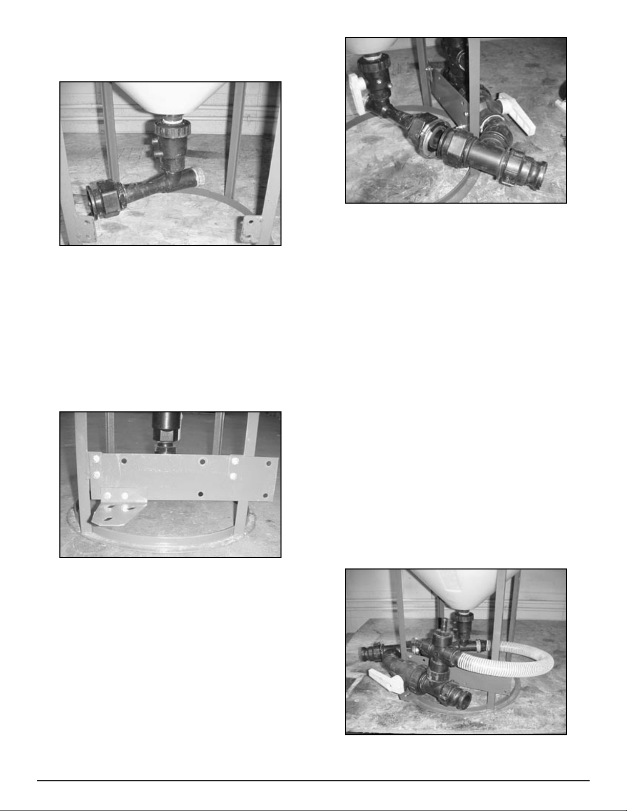
Step 2
Venturi package assembly
Figure H1-4.3
Thread venturi assembly to anti-vortex fitting on tank bot-
tom. Be sure to use sealant as per instructions.
NOTE: the discharge end of the venturi once installed
should point to the left hand side behind tabs. (See Fig.
H1-4.3)
Step 3
Bracket installation
Figure H1-4.4
Install venturi bracket to tabs on the Handler frame as
shown in Fig. H1-4.4 using ¼” x 1” bolts. Do not tighten
completely yet.
Install smaller ball valve support bracket on to venturi
bracket using 5/16” x ¾” bolts. Do not tighten completely
yet. (See Fig. H1-4.4)
1.
•
2.
3.
Figure H1-4.5
Attach bypass valve assembly to venturi assembly using
stainless steel flange clamp (25-FC200) and gasket (25-
150G) making sure that the 2” ball valve (10-10230) sits on
the support bracket. Do not tighten clamp completely yet.
(See Fig. H1-4.5)
Step 4
Bypass valve installation
Fasten 2” ball valve to support bracket using 5/16” x ¾”
bolts, 3/8 flat and 5/16 lock washer.
Tighten all bolts and clamps.
Step 5
Hose and clamp installation
Thread female end of hose barb on venturi hose assembly
on the intake side of the venturi (86-HV150).
Note: Use Sealant on both male and female threads.
Important: Make sure venturi nozzle is in place before
installing venturi hose.
Figure H1-4.6
4.
1.
2.
1.
•
11Handler I, II & III Operator’s Manual - October 2008
Attach the other end of the venturi hose assembly to the
bypass assembly. (See Fig. H1-4.6) Fasten hose with MC24
hose clamps (54-75624)
Cut and attach the appropriate length of ¾” hose (54-79200)
to connect the hose barb on the agitation valve assembly to
the hose barb on the top left hand side of the bypass assem-
bly. (See Fig. H1-4.7) Fasten hose with MC12 hose clamps
(53-75612)
Step 5
Hose and Clamp Installation
Figure H1-4.7
Cut and attach the appropriate length of ¾” hose to connect
the hose barb on the rinse valve assembly to the hose barb
on the top of the bypass assembly. (See Fig. H1-4.7) Again
fasten hose with MC12 hose clamps.
Tighten all fittings, bolts and hose clamps as necessary.
NOTE: Also check fly nut on anti-vortex fitting on tank
bottom. Tighten as necessary using pump pliers.
Your Handler 1-i15T is now completely assembled. Instructions
for the manifold package will follow. You may now continue to
the operation section of the manual starting on page 28.
2.
3.
1.
2.
•
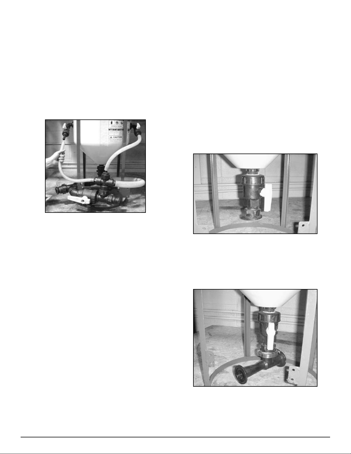
Manifold System
Step 1
Agitation & rinse valve installation
Assemble and thread agitation valve assembly (see Fig.
H1-4.1) into the ¾ bulkhead on the left side of the tank. (See
Fig.4.2 H1-4.2)
Note: Apply sealant before installing.
Install assemblies so that the hose barb points to the front.
(Bracket side of tank.) (See Fig. H1-4.2
Thread rinse valve assembly (See Fig. H1-4.1) into the ¾”
bulkhead on the right side of the tank. (See Fig. H1-4.2)
Step 2
Venturi assembly
Figure H1-4.8
Thread venturi valve assembly on to anti-vortex fitting on
tank bottom. Position valve handle for easy access.
(See Fig H1-4.8)
NOTE: Be sure to use sealant as per instructions
Figure H1-4.9
Attach venturi to valve assembly flange with clamp and gas-
ket. Do not tighten completely yet. Position discharge end
of venturi so it points to the front left (in-between the tabs
welded on the frame). (See Fig H1-4.9)
1.
•
2.
3.
1.
•
2.

12 Handler I, II & III Operator’s Manual - October 2008
Step 3
Bypass valve installation
Attach coupler (25-M220200CPG) to discharge end of ven-
turi using (25-FC200) flange clamp and (25-150G) gasket.
Attach 2” manifold tee (25-M220TEE) to coupler using (25-
FC220) flange clamp and (25-200G) gasket. Make sure stem
of tee is pointed upwards.
Figure H1-4.10
Position manifold tee so it is tight against the left hand side
of the front (in-between tabs welded on the frame.) (See Fig.
H1-4.10)
Continue attaching manifold fittings using the appropriate
clamps and gaskets as shown. (See Fig. H1-4.10)
Note: Make sure venturi nozzle is in place before install-
ing venturi hose. Make sure arrow on venturi (Flow
direction) is pointed to the front.
Venturi Nozzle Placement
1.
2.
3.
4.
•
Step 4
Bracket installation
Figure H1-4.11
Install venturi bracket (86-H1i15VBPO) to tabs on Handler
frame as shown in Fig. H1-4.11 using ¼” x 1” bolts. Do not
tighten completely yet. (See Fig. H1-4.11)
Figure H1-4.12
Attach completed assembly to venturi bracket (86-
H1i15VBPO) using 3/8”x 2 ½” U-bolts (67-UB38-250)
(See Fig. H1-4.12)
Tighten all bolts and clamps
1.
2.
3.
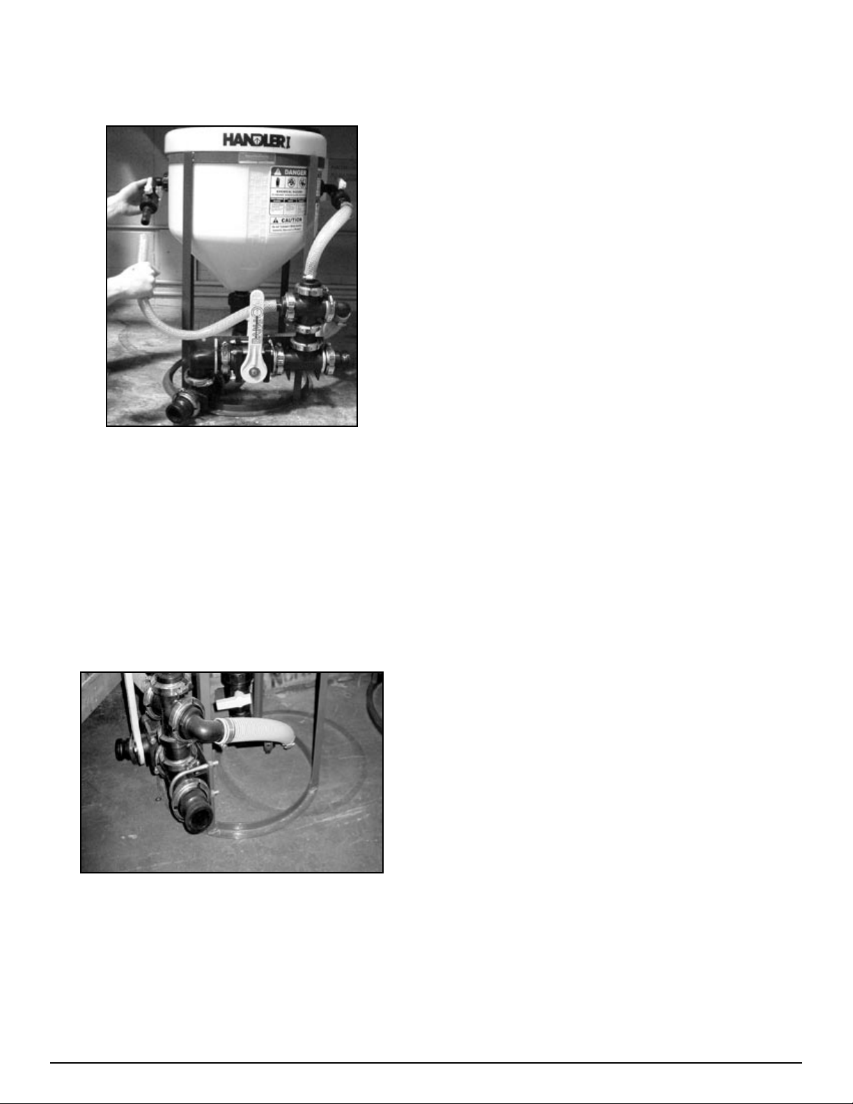
13Handler I, II & III Operator’s Manual - October 2008
Step 5
Hose and clamp installation
Figure H1-4.13
Cut and attach the appropriate length of 1” hose (57-79210)
to connect the hose barb on the top left hand side of the
bypass assembly. Fasten hose with MC12 hose clamps (53-
75612) (See Fig. H1-4.13)
Cut and attach the appropriate length of 1” hose to connect
the hose barb on the rinse valve assembly to hose barb on
the rinse valve assembly to the hose barb on the top of the
bypass assembly. Again fasten hose with MC12 clamps.
(See Fig. H1-4.13)
Figure H1-4.14
Measure, then cut and attach the appropriate length of 1 ½”
PVC suction hose (54-79050) to connect the venturi to the
manifold fitting assembly. (See Fig. H1-4.14) Fasten with
MC24 hose clamps (53-75624).
Hint: warm hose ends and barbs before trying to install the
hose. In addition, silicone spray can be applied to hose ends
to make installation easier.
1.
2.
3.
4.
Tighten all fittings, bolts and hose clamps as necessary.
Note: Also check flynut on anti-vortex fitting on tank bot-
tom. Tighten as necessary using pump pliers.
The assembly of your Handler 1-i15M is now complete.
Continue to the operation section of the manual on page 28.
5.
6.
14 Handler I, II & III Operator’s Manual - October 2008
Handler II Assembly
Overview
Assembly of your Handler 2 (without pump) follows four basic
steps:
Rinse valve and agitation fitting assembly and installation.
Venturi bracket and plate installation.
Three way valve support bracket installation
Venturi package assembly and installation.
If you have purchased a Handler 2 with a pump or recirculation
package then there are two additional Steps:
Pump bracket installation.
Pump and recirculation package installation.
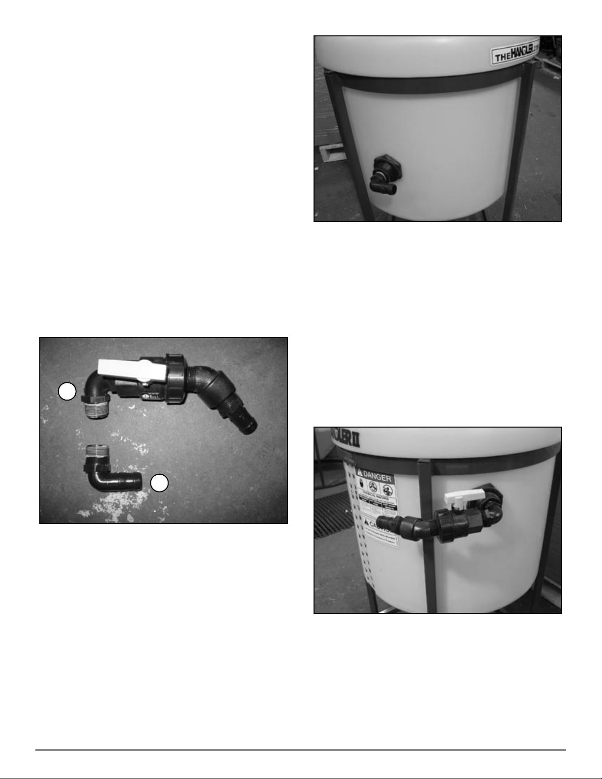
Step 1
Rinse valve and agitation fitting assembly
and installation
FIgure H2-4.1
Agitation Fitting Installation (Figure H2-4.1, “A”).
Install 1” MPT X 1” HB 90 (25-HB100-90) on to 1” bulk-
head on left side of tank. See figure H2-4.2. (Apply sealant
before assembling - see notes on page 37)
1.
2.
3.
4.
1.
2.
1.
Figure H2-4.2
Rinse Valve Assembly (Figure H2-4.1, “B”)
Install one 1” MPT X 1” MPT elbow (10-10980) on to 1”
single union ball valve (25-UV100FP) on end opposite of
union. (Apply sealant before assembling - see notes on
page 37)
Install 1” MPT X 1” Hose Barb (25-HB100) onto end of
street elbow.
Install 1” street elbow 45 degree (25-SL100-45) into union
side of ball valve.
Attach the above assembly to 1” bulkhead on right side of
tank (see figure H2-4.3).
Figure H2-4.3
1.
2.
3.
4.
A
B
15Handler I, II & III Operator’s Manual - October 2008
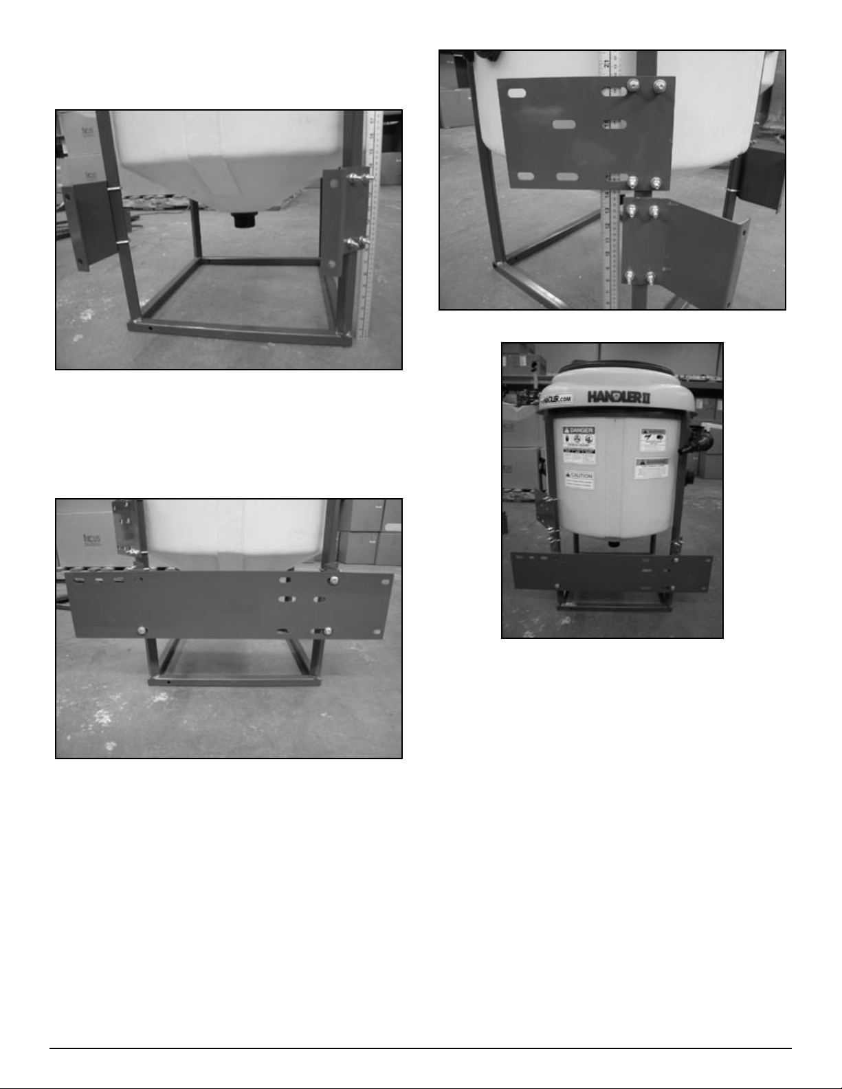
Step 2
Venturi bracket and plate installation
Figure H2-4.4
Mount angled frame brackets (86-HAFB) to frame as shown
in figure H2-4.4. Use two 1” U-bolts (67-UB025-100) per
bracket. Bottom of bracket should be 7” from bottom of
frame. NOTE: Tighten only enough to prevent slipping.
Figure H2-4.5
Mount venturi mounting plate (86-HVMP) on to angled
frame brackets as shown in figure H2-4.5 . Use three 5/16”
X 1” bolts (67-CSH5C516-1p) – two on the right side and
one on the lower left side. Do not tighten completely yet.
Hint: if angle frame brackets are not perpendicular to frame
tap with a mallet to align them.
1.
2.
Figure H2-4.6
Figure H2-4.7
Mount intake support plate (86-HISP) to frame 14 1/2” from
the base as shown in figure H2-4.6 and H2-4.7. Use two 1”
U-bolts (67-UB025-100). Do not tighten completely yet.
Go to next step (Three way valve support bracket installa-
tion).
3.
4.
16 Handler I, II & III Operator’s Manual - October 2008
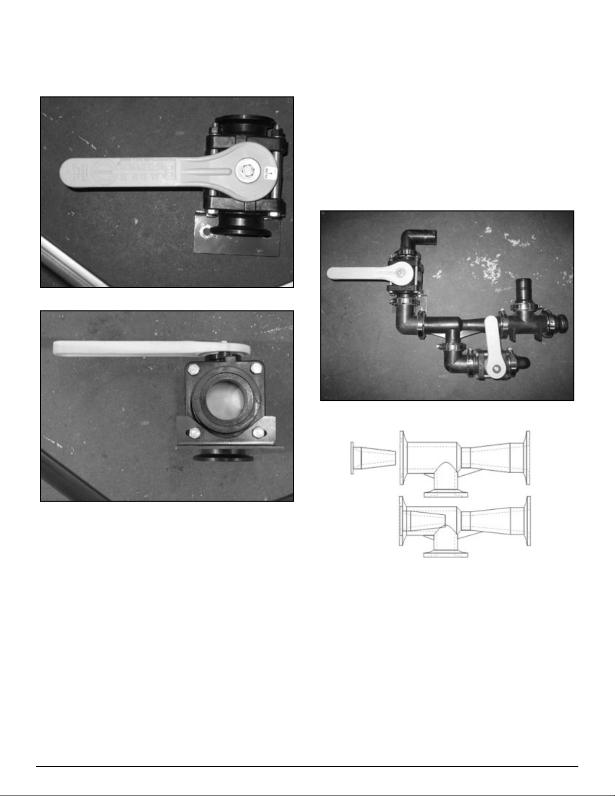
Step 3
Three way valve support bracket
installation
Figure H2-4.22
Figure H2-4.23
Install 2” three way valve support bracket (86-VASB2) on
to three way valve as shown in Figure H2-4.22 and H2-4.23
NOTE: handle operation should have closed position to left
when looking at front of valve.
Go to next Step (Venturi package assembly and installa-
tion).
Step 4
Venturi package assembly and installation
Hints:
Lay all parts out first.
Open FC200 and FC220 clamps slightly larger to make as-
sembly easier.
Open FC100 clamps completely to make assembly easier.
1.
2.
•
•
•
Part Number 25-M220CPG90 has long and short side. At-
tach short side to venturi and long side to 3 way ball valve
(25-MV220BL) as shown in figure H2-4.8
Start assembly at discharge end and work towards other end
(intake).
Venturi comes with nozzle insert, will not run without.
Do not install 2” bypass hose (54-79250) until last.
Warm hoses before installing – use heat gun or pail of hot
water.
Lubricate hose barbs with liquid dish soap or silicone based
lubricant to make installation easier.
Assemble and install 1” fittings last.
Figure H2-4.8
Venturi Nozzle Placement
Assemble manifold venturi package as shown in figure H2,
H3-4.8. Do not tighten completely yet.
•
•
•
•
•
•
•
1.

17Handler I, II & III Operator’s Manual - October 2008
Figure H2-4.9
Install partial assembly on to venturi mounting plate as
shown in figure H2-4.9. Use two 5/16” X 1” bolts. Do not
tighten completely yet.
Install two 2 ½” U-bolts (67-UB038-250) to hold assembly
to plate. Do not tighten completely yet.
Figure H2-4.10
Assemble remaining 2” fittings as shown in figure H2-4.10.
2.
3.
4.
Figure H2-4.11
Mount second assembly to first as shown in figure H2-4.11
(use 25-FC220 clamp and 25-200G gasket). Do not tighten
completely yet.
Install 2 ½” U-bolts (67-UB038-250) to hold second as-
sembly to intake support plate. See figure H2-4.11. Do not
tighten completely yet.
Figure H2-4.12
Assemble 1” fittings as shown in figure H2-4.12.
5.
6.
7.
18 Handler I, II & III Operator’s Manual - October 2008
Figure H2-4.13
Install 1” fitting assembly as shown in figure H2-4.13. Do
not tighten completely yet.
Tighten flange clamps on 2” fittings.
Tighten U-bolts.
Tighten remaining bolts.
Align 1” fittings and tighten flange clamps.
Figure H2-4.14
Install 2” bypass hose (54-79250) and secure with two
clamps (53-75632) per end as in figure H2-4.14.
Hint: Install hose at bottom end and ensure proper length.
Heat other end and install hose barb. Attach hose barb to
assembly.
Measure, cut and install 1” clear braided hose (54-79210)
for agitation and rinse lines. Secure with clamps (53-756-
12).
8.
9.
10.
11.
12.
13.
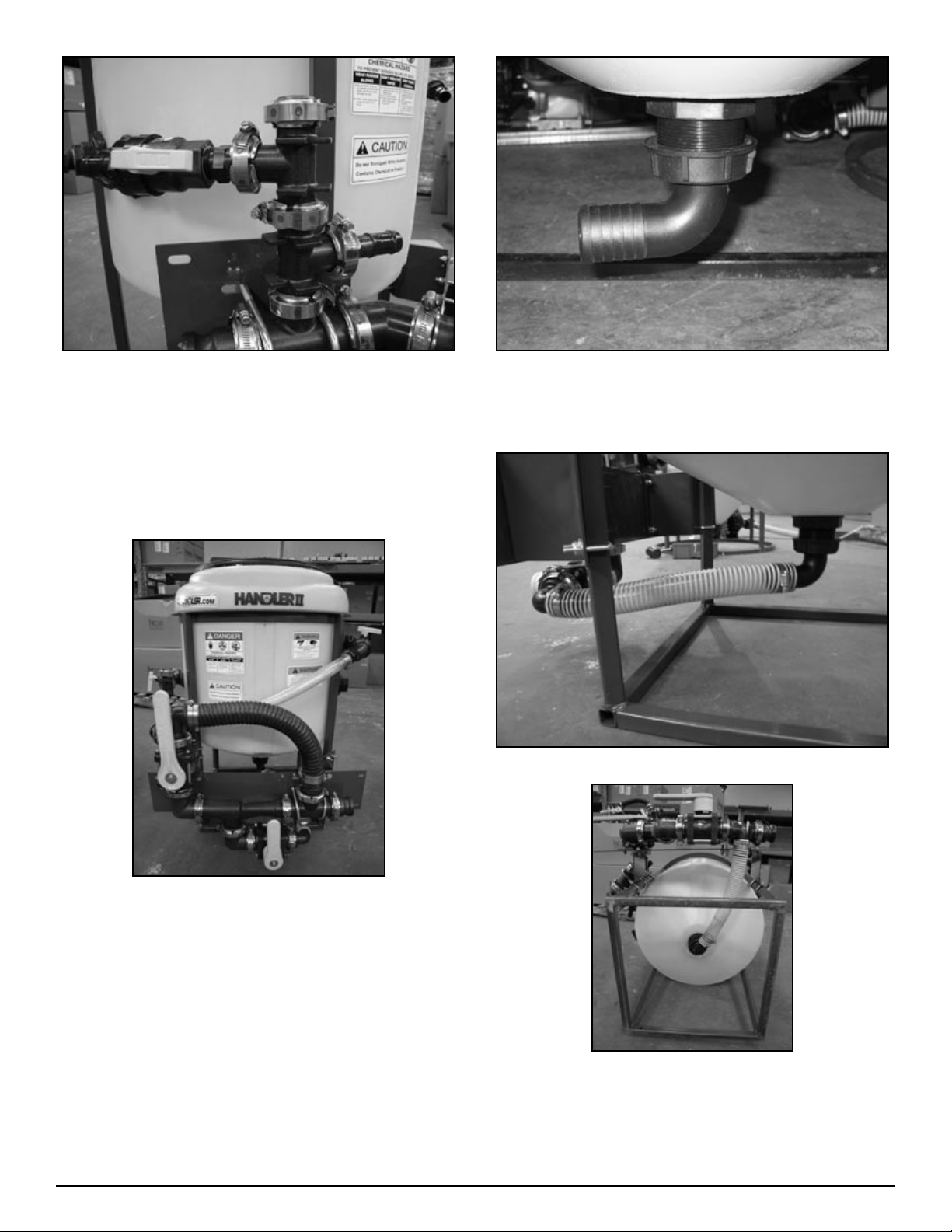
14.
Figure H2-4.15
Install 2” FPT X 1 ½” HB 90 degree fitting (10-10910)on to
bottom of tank, see figure H2-4.15
Figure H2-4.16
Figure H2-4.17
Measure, cut, and install 1 ½” PVC suction hose (54-79050)
that goes between tank and venturi valve. Secure with
clamps (53-75624). See figure H2-4.16 and H2-4.17.
15.
16.

19Handler I, II & III Operator’s Manual - October 2008
Step 5
Pump bracket installation
Figure H2-4.18
Fit pump bracket into bottom of tank frame (see figure H2-
4.18).
Use two 5/16” X 1 1/2’” bolts and two 5/16” locking nuts to
secure bracket to frame.
Step 6
Pump and recirculation
package installation
Mount pump to pump bracket using four 5/16” X 1 ½”L
bolts, four 5/16” locking nuts and eight flat washers.
Figure H2-4.19
Install 2” Tee (10-11100) to bottom of tank (use pipe seal-
ant) see figure H2-4.19.
1.
2.
1.
2.
Figure H2-4.20
Figure H2-4.21
Install fittings as shown in figure H2-4.20 and H2-4.21.
If using a pump/motor combination different than shown in
the above figures may require repositioning of the pump to
direct exhaust away from the tank. This may require drill-
ing extra holes in plate.
3.
4.
20 Handler I, II & III Operator’s Manual - October 2008
Handler III Assembly
Overview
Assembly of your Handler 3 (without pump) follows four basic
steps:
Rinse valve and agitation fitting assembly and installation.
Venturi bracket and plate installation.
Three way valve support bracket installation.
Venturi package assembly and installation.
If you have purchased a Handler 3 with a pump or recirculation
package then there are two additional steps:
Pump bracket installation.
Pump and recirculation package installation.
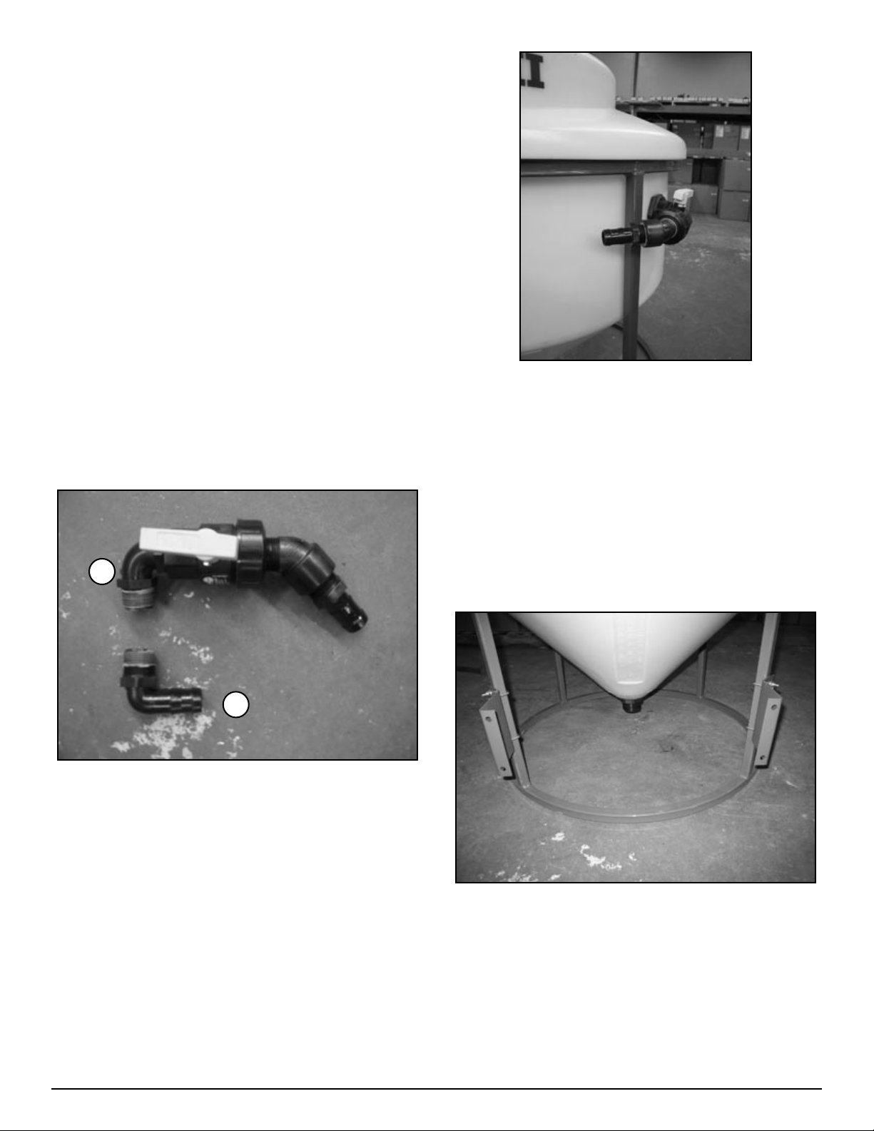
Step 1
Rinse valve/agitation fitting assembly and
installation
Figure H3-4.1
Agitation Fitting Installation (figure H3-4.1, “A”).
Install 1” MPT X 1” HB 90 (25-HB100-90) on to 1” bulk-
head on left side of tank. See figure H3-4.2. (Apply sealant
before assembling - see notes on page 37)
Rinse Valve Assembly (figure H3-4.1, “B”)
Install one 1” MPT X 1” MPT elbow (10-10980) on to 1”
single union ball valve (25-UV100FP) on end opposite of
union. (Apply sealant before assembling - see notes on
page 37)
1.
2.
3.
4.
1.
2.
1.
1.
Figure H3-4.3
Install 1” street elbow 45 degree (25-SL100-45) into union
side of ball valve.
Install 1” MPT X 1” Hose Barb (25-HB100) onto end of
street elbow.
Attach the above assembly to 1” bulkhead on right side of
tank (see figure H3-4.3).
Step 2
Venturi bracket and plate installation
Figure H3-4.4
Mount angled frame brackets (86-HAFB) to frame as shown
in figure H3-4.4. Use two 1” U-bolts (67-UB025-100) per
bracket. Bottom of bracket should be 7” from bottom of
frame. NOTE: Tighten only enough to prevent slipping.
2.
3.
4.
1.
A
B
This manual suits for next models
2
Table of contents
Popular Farm Equipment manuals by other brands


Tatu Marchesan
Tatu Marchesan RC2E 4500 instruction manual

Pottinger
Pottinger TERRASEM 3000 T Standardline Mounting instructions

ORKEL
ORKEL GP 1260 Operator's manual

Vicon
Vicon Extra 328 operating manual

IXOM
IXOM SolarBee SB2500PW owner's manual

Stocks AG
Stocks AG Fan Jet Mini 65 Original Operating Manual and parts list