Meyer's VB560 User manual

INSTRUCTION AND PARTS BOOK - Rev. O5
HEAVY DUTY MANURE SPREADERS
MODEL: VB560
Manufactured in DORCHESTER,WISCONSIN by
MEYER’SEQUIPMENT
Mfg. Corp.
DO NOT -
NEVER -
Operate This Spreader Until You Have
Completely Read This Book!
Repair or Clean This Spreader While
PTO is Engaged!

2 | P a g e
MODEL SPECIFICATIONS
Width of Box Inside
61-1/4”
Overall Width
9’ 5”
Length of Box Inside
213”
Depth
46”
Overall Length
29’ 3-1/4”
Overall Height (Front)
106-1/2”
Ground Clearance
15”
App. Capacity (Bushel)
560
App. Capacity (Struck Cu. Ft.)
370
App. Weight
11,980 LBS
Loading Height
82-1/2”
Apron Chain (Standard)
Twin #67P11
Apron Chain (Optional)
Twin #667XH Pintle
Beaters
Twin Ø 34-5/8” Vertical Beaters,
w/ 15MM Thick Spiral Flighting
Spindle Diameter
3-1/8” Standard
Spindle/Hub Load Rating –Each
12,000 LBS
Tire Size (Standard)
1600-R20
Tire Size (Optional)
600/55 x 26.5 Flotation Tires
PTO Speed
1,000 RPM
Min. Tractor Horsepower
150
Min. Hydraulic Flow
14 GPM

3| P a g e
INTRODUCTION
Congratulations on the purchase of your new Meyer’s
Manure Spreader. With its optional equipment this is
the simplest, most flexible system on the market today.
With proper operation and preventative maintenance, it
will last for many years.
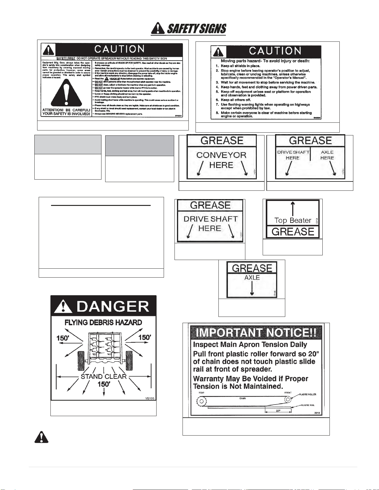
This SAFETY ALERT SYMBOL means
ATTENTION! BE CAREFUL! YOUR SAFETY IS
INVOLVED! It stresses an attitude of HEADS UP FOR
SAFETY. When you see this symbol, be alert to the
possibility of PERSONAL INJURY and carefully read
themessagethatfollows.
WARNING:
NEVER OPERATE WITHOUT ALL COVERS,
SHIELDS AND GUARDS IN PLACE. KEEP HANDS,
FEET AND CLOTHING AWAY FROM MOVING
PARTS. SOME COVERS AND GUARDS HAVE
BEEN REMOVED FOR ILLUSTRATIVE PURPOSES
ONLY IN THIS MANUAL. FAILURE TO HEED MAY
RESULT IN SERIOUS PERSONAL INJURY OR
DEATH.
At the front of this manual is a Product Registration and
Inspection Certificate. Be sure your dealer has
completed this certificate and forwarded a copy to the
manufacturertovalidatethemanufacturer’s warranty.
The product model and serial number are recorded on this
certificate for your convenience and for proper identification
of your spreader by your dealer and the manufacturer when
orderingrepairparts.
The serial number plate is found on the upper left front
corner of the spreader box or stamped in the left channel at
the front. For information on ordering repair parts, refer to the
repair parts section of this manual. Orders must list the
complete description, correct part number, and total amount
required.
All references to right hand and left hand apply to the
product as viewed from the rear of the machine and facing
the direction of forward travel.
You are urged to study this manual and follow the
instructions carefully. Your efforts will be repaid in better
operation and service as well as a savings in time and repair
expense. Failure to read this manual and understand the
machine could lead to serious injury. If you do not understand
instructions in this manual, contact either your dealer or
Meyer’s Equipment Manufacturing Corp.
This supersedes allprevious published instructions.
Contact Information
Meyer’s Equipment Mfg. Corp.
701 W Bus Cty Rd A
P.O. Box 406
Dorchester, WI 54425
Phone: (715)-654-5200
Fax: (715)-654-5558
Email: emcdorchester@tds.net

4 | P a g e
TABLE OF CONTENTS
INTRODUCTION..................................................................................................................................................... 3
SAFETY.......................................................................................................................................................... 6
SAFETYSIGNS
................................................................................................................................................. 8
MANURE SPREADER SAFETY ........................................................................................................................ 10
MANDATORYSAFETYSHUTDOWNPROCEDURE
............................................................................................... 11
PRE-OPERATION.................................................................................................................................................. 12
GENERAL................................................................................................................................................................... 12
TRACTOR HITCH AND PTO REQUIREMENTS ............................................................................................................ 12
TRACTOR SIZE REQUIREMENTS ................................................................................................................................. 13
HYDRAULICSYSTEM.................................................................................................................................................. 13
TRANSPORTING ........................................................................................................................................................ 15
OPERATION......................................................................................................................................................... 16
TRACTOR HOOKUP ................................................................................................................................................... 16
LOADING................................................................................................................................................................... 16
UNLOADING ............................................................................................................................................................. 16
MANDATORY SAFETY SHUTDOWN PROCEDURE ............................................................................................ 17
MAINTENANCE,ADJUSTMENTS & LUBRICATION
....................................................................................................... 18
WHEEL AND TIRE MAINTENANCE AND REPAIR ....................................................................................................... 18
LOCK RING RIM......................................................................................................................................................... 18
REAR-AUTOMATIC OVER RUNNING CLUTCH ........................................................................................................... 18
MANDATORY SAFETY SHUTDOWN PROCEDURE ........................................................................................... 18
ADJUSTMENTS.......................................................................................................................................................... 19
LUBRICATION............................................................................................................................................................ 19
CLEANING AND STORAGE......................................................................................................................................... 21

5| P a g e
REPAIRPARTS
...................................................................................................................................................... 22
MAIN FRAME & BOX PARTS ......................................................................................................................................... 22
HYDRAULIC END GATE & RELATED PARTS.................................................................................................................... 24
JACK ASSEMBLY............................................................................................................................................................ 26
AXLES, WHEELS, SPINDLES AND RELATED PARTS......................................................................................................... 28
DRIVE TRAIN, VERTICAL BEATERS................................................................................................................................. 30
APRON AND RELATED PARTS, STANDARD 67P11......................................................................................................... 32
APRON AND RELATED PARTS, OPTIONAL 667XH PINTLE ............................................................................................. 34
LUBE BANK, APRON SHAFT........................................................................................................................................... 36
BEATER HEAD ASSEMBLY, 15MM STANDARD.............................................................................................................. 38
VERTICAL BEATERS & RELATED PARTS ......................................................................................................................... 40
VERTICAL BEATER LUBRICATION KIT............................................................................................................................ 42
APRON DRIVE GEARBOX............................................................................................................................................... 44
REMOVABLECVTELESCOPINGUNIVERSALJOINTASSEMBLYWITHGUARD, TRAILER TO TRACTOR ....................................... 46
35E UNIVERSALJOINT,TELESCOPINGASSEMBLYW/ GUARD-REARWITH OVER- RUNNINGCLUTCH............................... 47
YOKE & CLUTCH HUB ASSEMBLY ................................................................................................................................. 48
OVER-RUNNING CLUTCH ASSEMBLY............................................................................................................................ 49
STANDARD HIGHWAY LIGHTING .................................................................................................................................. 50
HYDRAULIC ASSEMBLY, END GATE .............................................................................................................................. 51
HYDRAULIC ASSEMBLY, APRON, STANDARD................................................................................................................ 54
HYDRAULIC ASSEMBLY, APRON, ELECTRIC FLOW CONTROL........................................................................................ 56
HYDRAULIC ASSEMBLY, APRON, MANUAL FLOW CONTROL........................................................................................ 58
WEIGH SCALE KIT.......................................................................................................................................................... 60
LIMITEDWARRANTYSTATEMENT
........................................................................................................................... 62

6 | P a g e
SAFETY
A brief definition of signal words that may be used in
thismanual:
DANGER: Indicates an imminently hazardous
situation that, if not avoided, will result in serious injury
or death.
WARNING: Indicates a potentially hazardous
situation that, if not avoided, could result in death or
serious injury, and includes hazards that are exposed
when guards are removed.
CAUTION: Indicates a potentially hazardous
situation that, if not avoided, may result in minor or
moderateinjury.
DECALS ARE ILLUSTRATED ON PAGES 7 and 8. J
K D
G
Also under
shield
H
ON PTO FRONT
HALF
E
FTypicalIllustration
CV
Located on Driveline
Shields under spreader
CAUTION: IF ANY SAFETY SIGN BECOMES UNREADABLE FOR ANY REASON, THE SIGN MUST
BE REPLACED WITH A NEW SIGN. IF THE SPREADER IS REPAINTED, ALL SAFETY SIGNS MUST BE
REPLACED. CONTACT YOUR DEALER OR MEYER’S EQUIPMENT MANUFACTURING CORP. IF YOU
REQUIRE ANY SHIELD OR SIGNS FOR REPLACEMENT.
B
B

7| P a g e
DECALS ARE ILLUSTRATED ON PAGES 7 and 8.
CAUTION: IF ANY SAFETY SIGN BECOMES UNREADABLE FOR ANY REASON, THE SIGN MUST BE
REPLACEDWITH A NEW SIGN. IF THE SPREADER IS REPAINTED, ALL SAFETY SIGNS MUST BE
REPLACED. CONTACT YOUR DEALER OR MEYER’S EQUIPMENT MANUFACTURING CORP. IF YOU
REQUIRE ANY SHIELD OR SIGNS FOR REPLACEMENT.
M
A
I
D
D
T
U
S
P
L
M
Q
L
D
M
D
I
A
U
P
S
R
T
L
M

8 | P a g e
SAFETY SIGNS
DECAL I. PART NO. 3001
CAUTION: IF ANY SAFETY SIGN BECOMES UNREADABLE FOR ANY REASON, THE SIGN MUST BE
REPLACEDWITH A NEW SIGN. IF THE SPREADER IS REPAINTED, ALL SAFETY SIGNS MUST BE
REPLACED. CONTACT YOUR DEALER OR MEYER’S EQUIPMENT MANUFACTURING CORP. IF YOU
REQUIRE ANY SHIELD OR SIGNS FOR REPLACEMENT.
DECAL C. PART NO. SW102
DECAL F. PART NO. 3004
DECAL H. PART NO. SW406
DECAL A. PART NO. VB107
DECAL B. PART NO. SW105
DECAL D. PART NO. 700
DECAL E. PART NO. 3003
DECAL G. PART NO. 3006

9| P a g e
DECAL J. PART NO. SW2001
DECAL K. PART NO. SW2000
DECAL L. REFLEC-
TIVE TAPE-YELLOW
PART NO. PM17-5910
CAUTION: IF ANY SAFETY SIGN BECOMES UNREADABLE FOR ANY REASON, THE SIGN MUST BE
REPLACEDWITH A NEW SIGN. IF THE SPREADER IS REPAINTED, ALL SAFETY SIGNS MUST BE
REPLACED. CONTACT YOUR DEALER OR MEYER’S EQUIPMENT MANUFACTURING CORP. IF YOU
REQUIRE ANY SHIELD OR SIGNS FOR REPLACEMENT
DECAL M. REFLEC-
TIVE TAPE-RED
PART NO. PM17-5915
DECAL P.
PART NO. VB101
DECAL Q.
PART NO. VB102
DECAL S.
PART NO. VB104
START UP PROCEDURE
1.
Make certain everyone is clear of machine before starting
engine or operation.
2.
Turn Flow Control to Slowest Position.
3.
Engage P.T.O.
4.
RAISE END GATE.
5.
Engage Tractor Hydraulic Lever to Full Flow Position.
6. Start Apron by Rotating Flow Control Dial Clockwise.
DECAL O. PART NO. 3011
DECAL U.
PART NO. VB106
DECAL V.
PART NO. 3014
DECAL R.
PART NO. VB103
DECAL T.
PART NO. VB105

10 | P a g e
MANURE SPREADER SAFETY
CAUTION
THERE ARE INHERENT HAZARDS ASSOCIATEDWITH THE OPERATION OF A MANURE SPREADER.
FOR YOUR SAFETY:
Never Enter Spreader Box While In Operation For Any Reason.
Only Properly Instructed People Should Operate The Spreader. Do Not Allow Children Or Inexperienced Persons
ToOperate Spreader.
Keep All Guards and Shields In Place. Moving Parts Can Crush And Dismember.
Clear The Area Before Equipment Start Up.
Keep Hands, Feet, and Loose Clothing Away From Moving Parts.
Do Not Go Near The Spreader Beaters While Machine Is Operating.
Make Sure The PTO Is Securely Locked To Both The Tractor And Spreader Before Operating The Unit.
Do Not Operate The PTO At Speeds Higher Than The Manufacturers Recommendations.
Highway Traffic Is Not To Exceed 20 Mph. The Tires Supplied Are For Farm Use Only And Are Not Designed For
Use Above This Speed Unless Equipped With High Speed Highway/Off-Road Farm Tires.
Use Adequate Safety Chains When Towing The Spreader.
The Use of a Slow moving Vehicle Sign Is Required on All Public Roads Unless Equipped with Flashing Hazard
Lights. Obey All Applicable Highway Safety Laws And Rules.
Always Use A Tractor Large Enough To Provide Sufficient Braking Assistance When Towing A Loaded Spreader.
Use CautionWhen Traveling Over Uneven Terrain And When Approaching Stops.
Do Not Load The Spreader Unless It Is Hitched To The Tractor.
Do Not Unhitch A Loaded Spreader From The Tractor, Leaving It Supported ByOnly The Jack.
Park Your Spreader on Level Ground and Place Blocks Ahead Of and Behind The Wheels Before Unhooking
From Tractor To Avoid Unexpected Rolling When Separated From The Tractor.
Do Not Allow Riders on Spreader.
FAILURE TO HEED MAY RESULT IN SERIOUS PERSONAL INJURY OR DEATH
CAUTION
THEREAREADDITIONALHAZARDSASSOCIATEDWITHTHESERVICEANDMAINTENANCEOF YOUR
SPREADER.
FORYOURSAFETY:
Inspect When First Delivered And Regularly Thereafter; That All Connections And Bolts Are Tight And Secure
BeforeOperating.
Retighten All Wheel Bolts After The First Hour Of Towing. Check Periodically Thereafter. See Maintenance,
Wheels.
Maintain Proper Tire Air Pressure At All Times. See Maintenance, Tires.
Always Wear Eye Protection When Operating Or Servicing Spreader.
Be Sure All Movement Has Stopped, The PTO Is Disconnected, The Tractor Is Shut Off And The Ignition Key Is
Removed Before Servicing The Spreader Or Components.
Escaping Hydraulic Fluid Under Pressure Can Penetrate The Skin And Cause Serious Injury. Relieve All
Pressure From The Hydraulic System Before Connecting Or Disconnecting The Lines Or Making Repairs. Check
All Hoses and Fittings Before Start-up and Periodically During Operation.
Never Make Any Alterations Or Modifications To This Equipment.
FAILURE TO HEED MAY RESULT IN SERIOUS PERSONAL INJURY OR DEATH

11 | P a g e
MANDATORY SAFETYSHUTDOWN PROCEDURE
BEFORE unclogging, cleaning, adjusting, lubricating or servicing the unit:
1.
Disengage the tractor PTO.
2.
Shut off the tractor engine, remove the ignition key and take it with you.
3.
Wait for all movement to stop.
4.
Remove the Telescoping PTO Drive and ALL power connections from the tractor.
ONLY when you have taken these precautions can you be sure it is safe to proceed. Failure to follow the above
procedure could lead to death or serious bodily injury.
Most farm accidents, like industrial, home and high-
way accidents, are caused by the failure of some
individuals to observe simple and fundamental
safety rules or precautions. For this reason farm
accidents, just as other types of accidents, can be
prevented byrecognizing the causes of accidents
and doing something about them before an
accident occurs.
Regardless of the care used in the design and
construction of farm equipment, there are many
points that cannot be completely safe-guarded
without interfering with accessibility and efficient
operation.
A careful operator is the best insurance against an
accident.
The complete observance of one simple rule would
prevent many thousand serious injuries each year.
That rule is “NEVER ATTEMPT TO CLEAN, OIL,
OR ADJUST A MACHINE WHILE IN MOTION”.
-NATIONAL SAFETYCOUNCIL
BEFORE ATTEMPTING TO OPERATE YOUR NEW SPREADER BE SURE TO READ THIS OWNERS MANUAL
AND FAMILIARIZE YOURSELFWITH THE MACHINE!! OBSERVE THE PRECAUTIONS IN THIS MANUAL FOR
SAFE OPERATION OF THIS MACHINE!!

12 | P a g e
PRE-OPERATION
GENERAL
Read the entire Owner’s Manual before attempting to
operate this manure spreader. Before attempting any
maintenance or repairs; always be sure all rotating
parts have stopped and that the tractor is shut off, dis-
connect the PTO, relieve all hydraulic pressure and
disconnect hydraulic hoses.
WARNING
NEVER OPERATE SPREADERWITH ANY GUARDS
OR SHIELDS REMOVED. FAILURE TO HEED MAY
RESULT IN SERIOUS PERSONAL INJURY OR
DEATH.
.1
Completely lubricate the unit as described in the
LUBRICATIONSection.
.2
Check and tighten the wheel lug nuts if required.
.3
Check and maintain the tire pressure according to
themanufacturer’s recommendation.
.4
Check the entire unit for loose bolts, damaged or
loose hydraulic fittings and hoses or other dam-
aged parts.
.5
The tractor half of the PTO drive shaft assembly
must be locked securely to the tractor output shaft.
The PTO drive shaft assembly is designed to operate
with tractors conforming to the industry standard
shown on figure 1 for 1000 RPM PTO output.
ADMARecommendations:
A tractor drawbar equipped with a clevis hitch
(hammer-strap) can cause interference with the PTO
driveline IID (implement input driveline). This
interference can cause serious damage to the IID or
the IID telescoping members. The clevis hitch on the
tractor must be removed.
If the implement (figure 2, top view) is attached to a
tractor with a clevis hitch (hammer-strap) style
drawbar, the hammer-strap must be removed to pre-
vent damage to the IID guarding or the IID telescoping
members.
If the implement (figure 2, lower view) is attached to a
tractor with an offset in the drawbar, be certain it is in
the down position to prevent damage to the IID
guarding or the IID telescoping members.
TRACTOR HITCH AND PTO
REQUIREMENTS
The spreader is designed to be operated by a 1000
RPM PTO tractor output.
FIGURE 1. TRACTOR DRAWBAR & PTO
SPECIFICATION
TRACTOR ELEMENT INPUT
MASTER SHIELD DRIVELINE (IID) IMPLEMENT
INPUT
CONNECTION
SHIELD (IIC)
WRONG
TRACTOR
MASTER SHIELD ELEMENT INPUT
DRIVELINE (IID)
WRONG
FIGURE 2. PTO ALIGNMENT

13 | P a g e
TRACTORSIZE REQUIREMENTS
The spreader does not have brakes. Towing the
spreadermust bedone safely. The ASAE (American
Societyof Agricultural Engineers) specifies thatthe
towing vehicle should weigh at least 2/3 as much as
the loaded implement to be reasonablysafe towing at
speeds up to 20 mph. This (20 mph) is also the
maximum recommendedtowingspeedfor the
spreader.
The loaded weight of your spreader willnaturally vary
with the moisture of themanure and you must con-
sider thatfor your conditions. The loaded weight
capacities as specifiedbythe spreadermanufacturer
are as follows:
TractorTowingSizeRequirements
Use the following chart for calculating the minimum
tractorweight.
MODEL
(struck
level)
SPREADEREMPTY
WEIGHT + LOAD = GW
MINIMUM
TRACTOR
WEIGHT UP
TO 20 MPH
VB560
(370ft3)
11,980+
= _
2/3of spread-
ergross
weight
Material Estimated Weight Per Cubic Foot
Material
lbs / Cu. Ft.
LimeSludge
110-115LBS.
DryFeedlotManure
63-65LBS.
ChickenLitter
63-65LBS.
CakeSludge
62-65LBS.
Semi-SolidManure
58-60LBS.
PenPackedManure
30-35LBS.
LiquidManure
63-65LBS.
SOURCE: ASAE
NOTE: HEAPEDLOADSHAVESIGNIFICANTLY
HIGHERCAPACITIESRESULTINGININCREASED
WEIGHT ANDHIGHERCENTER OFGRAVITY,
REQUIRINGEXTRAPRECAUTIONDURINGOP-
ERATION.
HYDRAULICSYSTEM
General
There are two hydraulic circuits on thespreader.
1.
Onecircuit powers the hydraulic end gate.
2.
The second circuit powers thehydraulic apron
drive. A check valve is installed in this circuit to
prevent operating the apron in reverse.
Therefore, the tractor requires two sets of remote
ports, one set for the hydraulic apron drive and one
set for the hydraulic end gate.
Threetypes of hydraulic operatingsystems are
available for the apron drive on the spreader.
1.
The Manual Flow Control system has an
adjustable flow control valve on the spreader
which is manuallycontrolled bytwisting a “control
hose” which is connected to the flowcontrol valve
on the spreader and the opposite end of the hose
is fitted with a handle to operate from the tractor
seat. See Figure 3.
FIGURE 3. MANUAL APRON CHAIN FLOW
CONTROL
2.
An Electric Flow Control system is available to
replace the“control hose” described above. This
system has a motorized flow control valve on the
spreaderand an electric control box placed on
the tractor is used to control this valve. See
Figure4.
3.
The Standard system utilizes tractor lever flow
control.This system requires thatthetractor have
anadjustable flowcontrol lever (rabbit/turtle)
operated valve, there is no adjustable flow
control valve on the spreader when this option is
purchased.

14 | P a g e
FIGURE4. OPTIONAL ELECTRIC FLOW VALVE
CONTROLLER
Set Up forOpen Or Closed Center Hydraulic
Systems
1.
Most late model tractors use a closed center
hydraulic system which onlypumps oilas
required. Some other tractors may have an open
center system which pumps oil continuously, in
which case provision must be made to allow
excess flow back to the tractor reservoir. If you
are not sure of your system, contact your tractor
dealer.
2.
Spreaders with manual or electric controlare
shippedfrom thefactory, set up for open center
tractors. Toconvert for a closed center, close the
ball valve byrotating the handle perpendicular to
the valve as illustrated on Figure 5.
3.
Spreaders with tractor lever operatedflowcontrol
(no flow control valve or ball valve on spreader)
are shipped from thefactoryset up for closed
center.If you require Open Center, then a
conversion must be made as illustrated on
Figure6.
NOTICE! For tractors with closed center system and
load sensing that has a priority flow circuit that is
manuallyadjustable, the ball Valve must beopen.
This is not a tractor lever operated system.
ELECTRIC CONTROL INSTALLATION FOR
OPTIONAL ON-BOARD FLOW CONTROL SYSTEM
1.
Locate the controller on the tractor where it is
easily accessible to operate.
2.
Connect the electrical leads to the tractor’s 12VDC
power source.
3.
When hooking up the spreader, connect the
controller to the motorized control valve at the
“twist-lock” connector.
FIGURE5. APRONFLOW CONTROL (OPTIONAL
ELECTRIC ILLUSTRATED)
FIGURE6.CONVERTING TRACTOR LEVER
OPERATED FLOW CONTROL TO OPEN CENTER

15 | P a g e
TRANSPORTING
General
Check for traffic constantly. Be sure you can see that
no one is attempting to pass you and that all traffic is
sufficiently clear from you before making any turns.
BE SURE THE SLOW MOVING VEHICLE SIGN IS
INSTALLED ON THE REAR OF THE SPREADER
FOR TRANSPORTING ON ROADWAYS. KEEP THIS
SIGN AND ALL REFLECTIVE DECALS CLEAN. FAIL-
URE TO HEED MAY RESULT IN SERIOUS PER-
SONAL INJURY OR DEATH.
CAUTION
REGULARLY CLEAN OFF THE REFLECTIVE TAPE
AT THE REAR AND SIDES OF THE SPREADER
WHEN TRANSPORTING IT ON THE HIGHWAY.
WARNING
The chain must be strong enough to hold the weight of
the loaded spreader. If using a grab hook at the end(s)
of the chain to secure the chain to itself, a hook latch
must be installed.
The length of the safety chain is not to be any longer
than necessary to turn without interference. If any
chain links or attachment hardware are broken or
stretched, repair before using. Store chain so it does
not corrode or become damaged. Do not use this
chain for other implements because the strength and
length of chain may not be adequate. Identify this
chain for use on this particular spreader.
Safety chain designed for this spreader can be ordered
on page 23.
Use Lights
Optional lights are offered for your spreader. Lights are
recommended for any spreader operated on public
roads and may be a requirement.
If equipped with lights, plug the electric plug into the
tractor trailer electrical receptacle when hooking
spreader to tractor.
DO NOT TOW AT SPEEDS GREATER THAN 20
MPH. FAILURE TO HEED MAY RESULT IN SERI-
OUS PERSONAL INJURY OR DEATH.
Operating speed is dictated by the terrain over which
you are traveling. Always use caution. Avoid traveling
on slopes or hills that are unsafe. Also beware of
slippery conditions such as traveling over areas
previously spread with manure. If possible, avoid
spreading over areas where manure has been
previouslyapplied.
If you will travel on public roadways and it is le-
gal to do so, you must know all rules governing
such operation. This will include lighting and
brake requirements in addition to traffic rules.
You may also be required to install a safety
chain on the spreader.
Safety Chain Use
CAUTION
ASAFETYCHAINSHOULD BEINSTALLED
TORETAINTHECONNECTIONBETWEEN
TRACTOR(OR OTHERTOWINGVEHICLE)
ANDSPREADERWHENEVERTRAVELING
ONPUBLIC ROADS. A SUGGESTED AT-
TACHMENTISILLUSTRATED.
WARNING
INTERMEDIATE SUPPORT
GRAB HOOK W/LATCH
SUGGESTED SAFETY CHAIN INSTALLATION

16 | P a g e
OPERATION
NEVER ENTER THE SPREADER BOX FOR ANY
REASONWITHOUT FIRST DISCONNECTING PTO
SHAFT FROM TRACTOR. DO NOT ALLOW
OTHERS IN THE BOX. ROTATING BEATER CAN
DISMEMBER OR KILL.
TRACTOR HOOKUP
FIGURE 7. SPREADER HOOK UP
CAUTION
DO NOT USE JACK EXCEPT WHEN SPREADER IS
EMPTY. JACKWILL NOT SUPPORT ADDED
WEIGHT FROM LOAD. UNBALANCED WEIGHT
MAY RESULT IN UNEXPECTED “TIP UP” OF THE
SPREADER.
1.
Hook the spreader hitch to the tractor drawbar
with 1 3/8” secured hitch pin.
2.
Raise the jack off the ground. Remove the jack
hub pin and rotate the jack to horizontal storage
position and secure with the pin, figure 7.
3.
Connect the PTO drive shaft to the tractor PTO
output shaft and be sure it is locked to the tractor
shaft.
4.
Connect the hydraulic hoses from the
spreader to remote ports on the tractor.
NOTICE! The spreader apron circuit has a check
valve in it so that the apron may not be operated in
the wrong direction. If the hoses are reversed, the
apron will not operate and the hoses should be
switched.
5.
If you have an optional on board flow control with
electric control system, plug the twist lock
connectors together. See figure 5.
LOADING
1.
Check that the end gate is closed, figure 8. When
the spreader is parked for loading, shift the tractor
to neutral or park and set the brakes. The moisture
content of the manure will determine how full the
spreader can be loaded so that no manure spills
out.
2.
You will probably be able to load solid manure at
least level with the top of the box while semi liquid
and liquid slurries will have to be less than full in
the spreader box.
NOTICE! It is unlawful to allow slurry to splash or leak
onto public roads.
FIGURE 8. HYDRAULIC END GATE,
VIEW FROM REAR
UNLOADING
KEEP AWAY AND KEEP OTHERS CLEAR OF RO-
TATING BEATERS AT REAR OF SPREADER. SERI-
OUS INJURY OR AMPUTATION COULD RESULT.
DANGER
DANGER

17 | P a g e
MAKE CERTAIN EVERYONE IS CLEAR OF EQUIP-
MENT BEFORE APPLYING POWER. FAILURE TO
HEED MAY RESULT IN SERIOUS PERSONAL IN-
JURY OR DEATH.
The rear beaters have been designed and tested to
provide the best spread pattern for most liquids and
semi-solid manure. However, the pattern will vary for
each specific condition. The factors that contribute
most to differing patterns will be moisture content and
the amount and length of bedding material. For most
typical conditions, the spread pattern should be uni-
form and about 30 feet wide or more for cattle manure
and about 20 feet wide for poultry manure. Plan your
spreading patterns so you do not have to travel over
previously spread manure which will be slippery, re-
sulting in poor traction. Traction on wet grass is also
poor.When the resulting pattern mayrequire that you
overlap during spreading, use precautions on slopes
and hills where you will experience a loss of traction by
traveling over ground with previously spread manure.
CAUTION
DO NOT OPERATE APRON CHAINWITHOUT
RAISING END GATE FIRST. FAILURE TO HEED
MAY RESULT IN EQUIPMENT DAMAGE.
1.
When you are ready to begin spreading
application on the field, slowly engage the tractor
PTO clutch and then increase PTO to operating
speed.
2.
Open the hydraulic end gate, figure 8, by
applying the tractor hydraulic lever. This can be
done while traveling forward to avoid a heavier
application at the edge of the field than desired.
3.
Once the end gate is Fully Open and the
PTO is up to speed, engage the apron.
4.
For standard non flow control systems, regulate
the apron speed with the tractor hydraulic system
adjustable flow control lever (rabbit/turtle icons).
5.
For electric flow control,turnthe electriccontrolto
“ON”. Turnthe knob CW toincreaseorCCW to
decreaseapplicationrate.Returnswitchto“OFF”
when spreadingis completed,figure4.
6.
For solid manure, start the apron at a slow rate of
speed.
7.
Start application onto the field. Increase the speed
of apron chain for a heavier application.
NOTICE! Do not feed frozen manure at a rate too fast.
The apron drive can feed faster than the beaters can
expel the material. When frozen chunks are present,
reduce apron speed to approximately 1/3, to allow the
beaters time to grind the chunks into small pieces.
8.
Further control of the application rate is possible
by the relationship of tractor engine speed to
ground speed (transmission gear selection). For
optimum trouble free performance it is
recommended to operate at or near engine PTO
speed.
9.
When the spreader is empty, stop the PTO.
10.
Stop the apron chain so there is no chain slat under
the hydraulic end gate, Figure 8. Then close the end
gate.
MANDATORY SAFETY
SHUTDOWN PROCEDURE
BEFORE unclogging, cleaning, adjusting, lubricating
or servicing the unit:
1.
Disengage the tractor PTO.
2.
Shut off the tractor engine, remove the ignition
key and take it with you.
3.
Wait for all movement to stop.
4.
Remove the Telescoping PTO Drive and ALL
power connections from the tractor.
ONLY when you have taken these precautions can
you be sure it is safe to proceed. Failure to follow the
above procedure could lead to death or serious bodily
injury.
WARNING

18 | P a g e
MAINTENANCE,ADJUSTMENTS& LUBRICATION
WARNING
DISCONNECTPTODRIVESHAFTANDHYDRAULIC
HOSESBEFORECLEANING,ADJUSTINGOR SER-
VICINGTHISMACHINE.FAILURETOHEED MAYRE-
SULTIN SERIOUSPERSONALINJURYOR DEATH.
WHEEL AND TIRE MAINTENANCE AND
REPAIR
WHEELS: Check periodically. The wheel studs should
be torqued to 297 foot pounds.
TIREPRESSURE:
1600-R20 Recommended Pressure –75 PSI
600/55 X 26.5 Recommended Pressure –52 PSI
LOCK RING RIM
WARNING
NEVER INFLATE BEYOND RIM OR TIRE MANU-
FACTURER’S APPROVED PSI RATING.WHILE IN-
FLATING, STAY OUT OF THE TRAJECTORY &
STAND CLEAR OF TIRE/WHEEL ASSEMBLY. A
TIRE BLOW OUT OR RIM/WHEEL FAILURE CAN
CAUSE SERIOUS INJURY OR DEATH.
Removing, replacing and repairing industrial tires and
rims with lock rings can be dangerous without proper
tools, equipment and training to perform this service. It
is recommended that this work be performed only by a
qualified tire repair shop.
DANGER
IF THE LOCK RING SHOULD BLOW OFF, IT AND
OTHER PARTS COULD FLY OFF WITH ENOUGH
FORCE TO INJURE OR KILL A PERSON. NEVER
STAND IN THE POTENTIAL BLOW OUT AREA AND
KEEP OTHERS AWAY.
REAR-AUTOMATIC OVER RUNNING
CLUTCH
(See figure 9)
1.
If the PTO drive becomes over loaded, the clutch
will disengage, causing an audible clattering
noise.
FIGURE 9. AUTOMATIC OVER RUNNING CLUTCH
2.
If the clutch disengages, stop tractor hydraulic
flow. Disengage the PTO and allow it to coast
down. The clutch will re-engage at slow speed if
the over load has subsided.
3.
At slow speed, re-engage the PTO and allow the
beaters to run freely. Restart the hydraulic flow
and resume operation.
4.
If the clutch will not re-engage, then the beaters
are still over loaded or plugged. It will be
necessary to manually unplug the beaters to
remove the clog. A foreign object such as a rock
may be found to be the cause of over load.
5.
When the clog has been cleared, restart the
tractor and at idle speed, engage the PTO until
the beaters fun freely. Increase the PTO speed
and then engage the hydraulic flow to operate
the apron drive and resume operation.
MANDATORY SAFETY SHUTDOWN
PROCEDURE
BEFORE unclogging, cleaning, adjusting, lubricating
or servicing the unit:
1.
Disengage the tractor PTO.
2.
Shut off the tractor engine, remove the ignition
key and take it with you.
3.
Wait for all movement to stop.
4.
Remove the Telescoping PTO Drive and ALL
power connections from the tractor.
ONLY when you have taken these precautions can
you be sure it is safe to proceed. Failure to follow the
above procedure could lead to death or serious bodily
injury.

19 | P a g e
A1
ADJUSTMENTS
Apron Chain
FIGURE 10. ADJUST APRON CHAIN FIGURE 11.
The apron chain is adjusted by(4) adjuster bolts
located on the front of the box frame, figure 13. Adjust
the 1-1/8” bolts so the chain is elevated above the
plastic slide rails for 20”as illustrated on figure 10.
When there is no more adjustment left on the adjuster
screws, loosen the nuts on the bolts and push the
bolts in as far as they will go. Then remove a link from
each chain and readjust the apron chain
NOTICE! Chain must run centered on the front nylon
rollers.
LUBRICATION
Grease bearings on top of Vertical Beater one pump
every8 hours, both sides by grease lines. Figures 11 and
12.
Maintain oil level in apron drive reducerat check
level plug, accessible at right,rearside.It holds 6 Qts.
Whenrequired,refillwithSAE85-140MolyFortified
gear lube or Synthetic SAE 75-90 gear lube.Figure 11.
Grease bearingson the driveshaftunder spreader
box,onepump every8 hours.Thesebearingsare
accessedbygreaselines,3 placeson RH sideof
machine. Figures11and 14.
There are two bearings at the front of the driveline
connecting to the PTO shaft. Grease these bearings
one pump every 8 hours. Figure 13.
Grease Pivot Hitch 2 pumps every 8 hours, each
grease zerk. Figure 13.
FIGURE 12.
FIGURE 13.
L1
SIGHT GLASS
L6
SHIELD
L3
L7
L6
L8
SIGHT GLASS
L1
L7
L12
L11
A1
A1
A1
L4 UNDERNEATH

20 | P a g e
FIGURE 14.
Grease the apron drive shafts, both sides of the
spreader bythe grease lines, 5 pumps every 8 hours.
Figures 11 and 12.
Grease the axle at both sides of the spreader by
the grease lines, 10 pumps every 8 hours. Figures 11
and 12.
Maintain oil level in vertical beater gearbox to site
gauge level. It holds 17-1/4 Qts.When required, refill
with SAE 85-140 Moly Fortified gear lube or Synthetic
SAE 75-90 gear lube. Figure 12.
Grease cross bearings on yoke (both ends of
PTO shaft) 1 pump every 8 hrs. Grease telescoping
shaft through slot in center of guard, 4-5 pumps every
8 hrs. Figure 15.
Specialattentionshouldbepaidtolubricatingthe
constantvelocityPTOdriveshaftassembly.Seefigure15.
FIGURE 15. PTO LUBRICATION
NOTICE!
SPREADER MUST BE SITTING
LEVEL FOR AN ACCURATE OIL
CHECK.
TO CHECK OIL LEVELS, PARK
SPREADER ON LEVEL GROUND,
AND USE JACK TO RAISE / LOWER
THE SPREADER BODY UNTIL IT IS
COMPLETELY LEVEL.
Other manuals for VB560
1
Table of contents
Other Meyer's Farm Equipment manuals
Popular Farm Equipment manuals by other brands

Hot Shot
Hot Shot DuraProd HUDX instructions

Blue Diamond
Blue Diamond Drum Mulcher Operation and maintenance manual

Blue Diamond
Blue Diamond Mini Series Operation and maintenance manual

Co-op
Co-op COMPOST BIN quick start guide

Euro Systems
Euro Systems MFL01 operating instructions

SaMASZ
SaMASZ DUO 680 Operator's manual